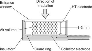
Figure 3.7) is defined by the cross-sectional area of the collecting electrode and the separation between the plates. Interactions with the lateral walls of the chamber generate ions primarily at the edges of the chamber which are collected by the guard ring and not by the collecting electrode.

Figure 3.7 Schematic diagram of a parallel plate ionization chamber. Ionization produced within the shaded volume of air is collected by the collector electrode. The guard rings minimize the effects of the chamber walls. The effective point of measurement is the inside surface of the entrance window.
Stay updated, free articles. Join our Telegram channel

Full access? Get Clinical Tree


