7 Topography of the Cranium, Intracranial Spaces, and Contained Structures
7.1 Cranial Vault
Five bones form the cranial vault, the neurocranium:
Occipital bone
Sphenoid
Paired temporal bones
Frontal bone
Paired parietal bones
The cranial vault and the nasal skeleton are closely related, with the lamina cribrosa of the ethmoid bone forming part of the cranial cavity together with the aforementioned bones.
7.1.1 Occipital Bone
The occipital bone forms the boundary of most of the posterior cranial fossa and is divided into four different parts:
Basal Part
Two lateral parts
Squamous part
All parts surround the foramen magnum (see ▶Fig. 3.24, ▶Fig. 3.25, ▶Fig. 4.8, and ▶Fig. 5.17).
The basal part forms the anterior edge of the foramen magnum and fuses in the 16th to 18th years of life with the sphenoid to form the clivus, a landmark for neuroimaging (see ▶Fig. 4.2c). The pons and medulla oblongata lie posterior to the clivus (see ▶Fig. 4.2a and ▶Fig. 4.2b). The two lateral parts are related to the temporal bones. The articular processes, the occipital condyles, protrude from their inferior surface and correspond to the atlas. The hypoglossal canal, through which the XIIth cranial nerve exits, lies superior to the occipital condyles (see ▶Fig. 4.3a, ▶Fig. 4.9, ▶Fig. 5.3a, and ▶Fig. 5.31).
The squamous part is roughly triangular and appears bent in the median plane and seems to be composed of an upper and lower part. An external occipital prominence, the external occipital protuberance, is seen protruding roughly from the center of the outer aspect of the squamous part, right at the border of the upper and lower part (see ▶Fig. 4.2c, 4.2d, ▶Fig. 4.8, ▶Fig. 5.1b, and ▶Fig. 5.6a). An internal occipital prominence, the internal occipital protuberance, lies on the inner aspect of the squamous part, opposite to its external counterpart (see ▶Fig. 4.2 and ▶Fig. 4.8). The confluence of sinuses is situated here, with the superior sagittal sinus draining into the transverse sinus. The dura of the transverse sinus also serves as the attachment for the tentorium of cerebellum, thereby forming an important topographic and neurosurgical boundary between the infra- and supratentorial regions.
7.1.2 Sphenoid
The sphenoid is located anteriorly and connected with the occipital bone and forms the central part of the base of the skull. Comparison with a wasp helps illustrate parts of the sphenoid:
Unpaired median portion of the sphenoid: “Body” of the wasp from which two “pairs of wings” protrude upward.
Lesser wings: First “pair of wings” of the wasp.
Greater wings: Second “pair of wings” of the wasp, below the lesser wings.
Superior orbital fissure: Cleft between both “pairs of wings” (see ▶Fig. 3.5d, ▶Fig. 3.18, ▶Fig. 4.1b, ▶Fig. 4.4c, ▶Fig. 4.4d, ▶Fig. 5.17, and ▶Fig. 5.35).
Pterygoid processes: Each with a medial and lateral plate (see ▶Fig. 3.5c, ▶Fig. 3.19, and ▶Fig. 5.3), paired “legs” suspended inferiorly from the body of the wasp.
The body of the sphenoid is shaped like a cube and contains the sphenoid sinus, which has been described in Section 8.2. The cerebral surface of the body of the sphenoid is related to the cribriform plate of the ethmoid through the spheno-ethmoidal suture. Behind this lies the “Turkish saddle”, the sella turcica, that forms the hypophyseal fossa, a deep depression that accommodates the pituitary gland. The hypophyseal fossa is bounded by the tuberculum sellae anteriorly and posteriorly by the dorsum sellae (see ▶Fig. 4.8 and ▶Fig. 5.35). The posterior clinoid process protrudes laterally from the dorsum sellae on either side (see ▶Fig. 5.35).
The paired lesser wings arise from the body of the sphenoid, each with two roots, encompassing the optic canal (see ▶Fig. 3.18 and ▶Fig. 5.36). The lesser wings form the boundary between the anterior and middle cranial fossae. The posteromedial edge of the lesser wing protrudes medially as the anterior clinoid process (see ▶Fig. 3.1b, ▶Fig. 3.6c, ▶Fig. 5.1b, ▶Fig. 5.19, and ▶Fig. 5.36).
Clinical Notes
Onodi cells are pneumatized cells of the posterior ethmoid, lying superolateral to the sphenoid sinus and extending into the anterior clinoid processes. This anatomical variant is of clinical relevance due to immediate proximity to the optic nerve and internal carotid artery, ignorance of which may result in iatrogenic injury. Pneumatization of the sphenoid sinus may also extend into the anterior clinoid processes, which is then called “spheno-optic recess”. Axial and coronal CT images should therefore be obtained while planning surgery on the paranasal sinuses.85 , 369 , 437 , 652
The greater wings of the sphenoid are paired structures arising from the posterior aspect of the sphenoid body. Two openings for nerves (second and third divisions of the Vth cranial nerve) perforate their roots, the foramen rotundum anteriorly and foramen ovale posteriorly. The foramen spinosum for the middle meningeal artery lies posterolateral to the foramen ovale. The greater wing of the sphenoid is related anteriorly to the maxilla at the pterygopalatine fossa, and to the orbit, forming part of the orbital wall. The temporal part of the greater wing of the sphenoid is directed laterally and forms a small part of the lateral cranial vault in the region of the temporal fossa.
The pterygoid process (see ▶Fig. 3.19) originates with two roots from the body of the sphenoid which follow a downward course along the lateral wall of the choana. The pterygoid canal runs between the two roots of the pterygoid process and ends finally in the pterygopalatine fossa. The pterygoid process splits into medial and lateral laminae or plates, enclosing a longitudinal groove, the pterygoid fossa (see ▶Fig. 3.19). The medial plate forms a hook-like projection, the pterygoid hamulus (see ▶Fig. 3.5c, ▶Fig. 3.5d, and ▶Fig. 4.4c) around which the tendon of the tensor veli palatine is wrapped; the lateral plate exhibits a rounded inferior border.
7.1.3 Temporal Bone
The paired temporal bones each form part of the base of skull and the lateral cranial vault. Each consists of four parts (five in the Anglo-American literature):
Petrous part: This part encloses the inner ear and forms the boundary between the middle and posterior cranial fossae in the region of the base of skull.
Tympanic part: The tympanic part forms the floor, anterior and lateral walls of the bony external auditory canal.
Squamous part: This part continues between the occipital bone, parietal bone, and sphenoid, and articulates at its inferior surface with the head of the mandible.
Styloid process.
Mastoid part: In the Anglo-American literature the mastoid is considered to be a part of its own, while based on the terminology by the FCAT (Federative Committee on Anatomical Terminology) there are the petrous, the tympanic and the squamous part plus the styloid process.
Petrous Part of Temporal Bone
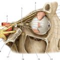
▶Fig. 7.1, ▶Fig. 7.2, ▶Fig. 7.3, ▶Fig. 7.4, ▶Fig. 7.5, ▶Fig. 7.6, ▶Fig. 7.7a illustrate the structure of the petrous bone and the internal auditory canal. The middle ear is a sound conducting system, primarily consisting of the tympanic cavity with contained auditory ossicles and the tympanic membrane, and is bounded on all sides by parts of the temporal bone. The inner ear is a sound processing system and balancing organ and lies entirely within the petrous bone.


The pyramid-like part of the temporal bone extending into the interior of the skull is called its petrous part and is the hardest bone in the body. The lateral aspect of the petrous bone together with the squamous part of the temporal bone forms the mastoid process, which is pneumatized by the tympanic cavity and contains mastoid air cells. The apex of the petrous bone is directed anteromedially while its base is directed posterolaterally. As noted earlier, the superior border of the petrous bone forms an acute angle of 55° with the median plane and represents the boundary between the middle and posterior cranial fossae. The apex of the petrous bone lies anteromedial to the cochlea (see ▶Fig. 7.1b). The lateral part of the petrous bone together with parts of the squamous form the roof of the tympanic cavity, the tegmen tympani. A prominent bony lamella forming the border between the petrous and squamous parts is the Koerner’s septum (see ▶Fig. 7.1d) and it is frequently well seen, traversing in the upper part of the tympanic cavity from posterolateral to anteromedial. A persistent petrosquamosus sinus is rarely visualized (1% of CT examinations) coursing along the border between the petrous and squamous parts.305
The inferior surface of the pyramid forms part of the outer base of the skull, floor of the tympanic cavity, and the bony part of the musculotubal canal. The petro-occipital synchondrosis (see ▶Fig. 7.1a, ▶Fig. 7.2a, and ▶Fig. 7.2c) lies medially and fuses after the 16th year of life.376 The foramen lacerum lies anterior to this synchondrosis and medial to the carotid canal (see ▶Fig. 7.1a), through which the greater and deeper petrosal nerves pass. The carotid canal begins in the center of the inferior surface of the pyramid and traverses anteromedially below the cochlea. The average distance between the carotid canal and the cochlea is a mere 1.2 m.636 The jugular foramen lies posterior to the carotid canal (see ▶Fig. 3.24, ▶Fig. 5.31, and ▶Fig. 7.1a). Its posterior part transmits the sigmoid sinus, while its intermediate part transmits the IXth, Xth, and XIth cranial nerves and the posterior meningeal artery and its anterior part the inferior petrosal sinus. The sigmoid sinus continues as the jugular vein below the jugular foramen. The distinction between the carotid artery and the jugular vein is more difficult on coronal CT sections due to suboptimal delineation of largely soft tissue boundaries but is distinctly seen on the axial image by the small bony lamella in the apical section. The tympanic opening of the auditory tube lies anterior and lateral to the carotid canal (see ▶Fig. 7.1a), while the tensor tympani lies immediately above it (see ▶Fig. 7.1b). The auditory tube and the tensor tympani run together in the musculotubal canal (see ▶Fig. 7.5).
The squamous part of the temporal bone forms part of the lateral wall of the skull, providing insertion for the temporalis. The zygomatic process arises anterolaterally with the masseter inserting on its inner surface. The squamous part is related anteromedially to the sphenoid, both of which form the floor of the middle cranial fossa. The sphenosquamous suture forms the boundary between the two bones (see ▶Fig. 7.1a). Corresponding inferior slices with sections through the middle cranial fossa also depict the foramen ovale (see ▶Fig. 7.1a and ▶Fig. 5.37), which transmits the mandibular branch of the trigeminal nerve and the venous plexus of the foramen ovale. The foramen the spinosum lies somewhat posterior and lateral to the above (see ▶Fig. 5.37 and ▶Fig. 7.1a), often remaining partially ossified, and contains the middle meningeal artery and the meningeal branch of the mandibular nerve (third division of the Vth cranial nerve). Anteroinferiorly the squamous part forms the roof of the temporomandibular joint and thereby the socket for the mandibular condyle (see ▶Fig. 4.13 and ▶Fig. 7.1a), posterior to which the tympanic part (see ▶Fig. 4.12 and ▶Fig. 7.1a) forms the posterior wall of the temporomandibular joint. The petrotympanic fissure (Glaserian fissure) lies at the posteromedial boundary of the temporomandibular joint and enters the mandibular fossa (see ▶Fig. 7.1b) with the chorda tympani and the anterior tympanic artery coursing through it. Merging with the tympanic part, the squamous part forms the roof of the external auditory canal together with the lateral aspect of the tegmen tympani. The squamous and petrous parts form the mastoid posteriorly, which first develops in childhood.
The incomplete ring-like structure formed by the tympanic part of the temporal bone, which encloses the floor, anterior and lateral aspects of the external auditory canal, closes inferiorly at about the age of 7 months. The external auditory canal is thus the sole component of the hearing and vestibular apparatus which completes its bony development only after birth. The bony part of the external auditory canal is about 16 mm long and continues laterally as its cartilaginous part. The external acoustic canal is separated from the tympanum at its medial end by the tympanic membrane. The caudal insertion of the tympanic membrane is identified on the coronal image by the tympanic annulus (see ▶Fig. 7.2b). The uppermost part of the membrane is the pars flaccida which lies directly below the scutum (see ▶Fig. 7.2a and ▶Fig. 7.2b), a spur which marks the medial boundary of the external auditory canal.
Middle Ear
The middle ear is a space enclosed on all sides by the temporal bone and contains the auditory ossicular chain, which transmits sound waves to the fluid-filled space of the inner ear. The tympanic cavity is divided into the following compartments: epitympanum (see ▶Fig. 7.1d and ▶Fig. 7.2a), mesotympanum (see ▶Fig. 7.2b), and hypotympanum (see ▶Fig. 7.2b); the mastoid antrum (see ▶Fig. 7.1d) characterizes the so-called atrium of mastoid cells. The mesotympanum represents a space lying medial to the tympanic membrane, with the epitympanum lying above it and the hypotympanum lying below. The lateral border of the tympanum is formed by the tympanic membrane and the tympanic and squamous parts of the temporal bone surrounding it. The auditory ossicular chain lies within the tympanic cavity and is composed of the malleus, incus, and stapes from lateral to medial (see ▶Fig. 7.5). The handle of the malleus (see ▶Fig. 7.1b) is inserted into the tympanic membrane and extends supero-anteriorly from somewhat below its center. Two thin folds, also called anterior and posterior mallear folds of the tympanic membrane on either side of the mallear handle, create a lax zone referred to as “pars flaccida”. It ends immediately below the scutum which is well seen on coronal CT. The rest of the ear drum is tightly stretched and is called the “pars tensa”. The so-called Prussak space lies between the pars flaccida and the neck of the malleus. The incudomallear joint is identified in the axial image typically as an “ice cream cone”, its anterior aspect being formed by the head of the malleus and its posterior part by the body of the incus. The long process of the incus extends to the stapes in inferior sections (see ▶Fig. 7.1b), articulating with head of the stapes to form the incudostapedial joint. The crura of the stapes are usually hardly defined, while the footplate of the stapes covers the oval window (see ▶Fig. 7.2b). The tensor tympani (see ▶Fig. 7.1b and ▶Fig. 7.2a) lies anteromedially above the auditory tube and extends posteriorly over a bony protrusion, the processus cochleariformis. The tendon of the tensor tympani (see ▶Fig. 7.1b, ▶Fig. 7.2a, and ▶Fig. 7.5) extends laterally to the head of malleus as a thin structure just anterior to the oval window. The stapedius arises within the pyramidal eminence (see ▶Fig. 7.1b and ▶Fig. 7.5). Its tendon extends anteriorly to the head of the stapes but is only inconsistently seen. The constant indentation of the sinus tympani (see ▶Fig. 7.1b) is seen medial to the pyramidal eminence.
Clinical Notes
Cholesteatomas of the ear are distinguished by their site of localization in the pars flaccida and the pars tensa. Early stage cholesteatomas of the pars flaccida are seen in Prussak’s space between the scutum and the ossicles, while those of the pars tensa are found initially in the region of the tympanic sinus, facial recess, and mastoid.
▶Fig. 7.6 illustrates the arterial supply of the tympanum and mastoid.
The facial nerve is an important landmark and runs through the petrous part of the temporal bone and the tympanum. It exits the brainstem laterally at the level of the pontomedullary junction and passes through the cerebellopontine angle into the internal auditory canal, which it exits at its lateral end, coursing superiorly over the cochlea in an anterior direction. Its course within the bony canal is called its “labyrinthine segment” (see ▶Fig. 7.1c). The nerve then enters the geniculate ganglion in an anterior direction (see ▶Fig. 7.1c), where it gives rise to the greater petrosal nerve, with a concurrent change in direction posteriorly thereby forming a bend called the geniculum of the facial nerve. The adjoining tympanic segment (see ▶Fig. 7.1c and ▶Fig. 7.2) runs along the medial wall of the tympanum above the oval window and below the lateral semicircular canal. A second change in direction occurs at the level of the sinus tympani at the second genu, beyond which the nerve courses inferiorly into the mastoid (see ▶Fig. 7.1a, ▶Fig. 7.1b, and ▶Fig. 7.1c). It exits the base of the skull through the stylomastoid foramen (see ▶Fig. 5.37b). The facial nerve gives off the chorda tympani within the mastoid, which runs backward superiorly and anteriorly through the tympanum, exiting it at the anterior wall through the petrotympanic fissure (see ▶Fig. 7.1b and ▶Fig. 7.5).
Inner Ear
Functional components of the inner ear include the organs of balance and hearing. The cochlea is the organ of hearing while the organs of balance consist of the utricle, saccule, and the semicircular canals. The three semicircular canals determine directional balance in space, while horizontal and vertical acceleration are perceived by the utricle and the saccule, respectively. The utricle and saccule lie together in the central vestibule, from which both the semicircular canals as well as the vestibulocochlear duct arise (see ▶Fig. 7.2b). All parts of the inner ear are enclosed in the bony labyrinth. The membranous labyrinth, filled with endolymph, is contained within. The space between membranous and bony labyrinths contains perilymph. Phylogenetically, the semicircular canals and the utricle are older than the cochlea and the saccule.
Clinical Notes
A serious malformation may involve the entire phylogenetically older part of the inner ear. An example is the CHARGE syndrome, a genetic defect that is associated with choanal atresia, cardiac malformations, colobomas of the eye, malformations of the genitourinary system, and ear deformities.
The bony labyrinth can generally be well evaluated on CT with optimal visualization of dense bony structures as well as identification of finer structures like the modiolus. Fluid-filled spaces such as peri- and endolymph are better seen on MRI. This diagnostic modality is also well suited for imaging the vestibulocochlear and facial nerves which appear as dark lines in the fluid-filled internal acoustic canal (see ▶Fig. 7.4).
From inferior to superior, the basal turn of the cochlea is the first structure of the inner ear to be visualized on temporal bone CT (see ▶Fig. 7.1a, also see ▶Fig. 7.7a), below which the internal carotid artery and the carotid canal are identified (see ▶Fig. 7.1a). The osseous spiral lamina is delineated as a line within the basal turn on MRI and CT (see ▶Fig. 7.3a and ▶Fig. 7.3b), dividing the cochlea into a superior scala vestibuli (see ▶Fig. 7.3a and ▶Fig. 7.3b) and an inferior scala tympani (see ▶Fig. 7.3a and ▶Fig. 7.3b). The scala media with the organ of Corti can usually not be identified using the current standard resolution. The bony prominence produced by the basal turn on the medial wall of the tympanum is called the promontory (see ▶Fig. 7.1b). The fossa of the round window (see ▶Fig. 7.1b and ▶Fig. 7.7a) appears as a black, air-filled space at the posterolateral end of the basal turn, immediately proximal to its transition to the vestibule. The oval window may be seen in transverse sections in the same or adjoining slices as the stapes (see ▶Fig. 7.1b and ▶Fig. 7.7a), but is often better visualized in the coronal image (see ▶Fig. 7.2b). Centered within the cochlea is a delicate, crown-shaped structure, the modiolus (see ▶Fig. 7.1b and ▶Fig. 7.7a), which is also well seen on MRI (see ▶Fig. 7.3 c). The boundary of the modiolus to the internal auditory canal forms the cochlear area, which transmits fibers of the cochlear nerve (see ▶Fig. 7.3c and ▶Fig. 7.3d). The opening of the internal auditory canal into the cochlea which leads the nerves into the cochlea is termed the cochlear aperture (see ▶Fig. 7.1b and ▶Fig. 7.2b). The facial and vestibulocochlear nerves pass into the internal auditory canal from the brainstem through the cerebellopontine angle (see ▶Fig. 7.1c and ▶Fig. 7.3e). The vestibulocochlear nerve (see ▶Fig. 7.3e), lying somewhat postero-inferior to the facial nerve, divides within the acoustic canal into its superior and inferior divisions and the cochlear nerve. The facial nerve is the one running most superiorly above the cochlea and anteriorly to the vertical crest (Bill’s bar) in its bony canal (see ▶Fig. 7.1c) toward the geniculate ganglion (see ▶Fig. 7.1c). Another narrow canal, the singular canal (see ▶Fig. 7.1c and ▶Fig. 7.3b), extends from the postero-inferior aspect of the internal auditory canal to the vestibule, and transmits the posterior ampullary nerve (see ▶Fig. 7.4) which arises from the inferior division. The rest of the branches from the superior and inferior divisions enter the vestibule somewhat further distally through the superior or inferior vestibular areas.
The vestibule (see ▶Fig. 7.1c) is seen as an oval structure in axial sections from which semicircular canals arise at different levels. The lateral semicircular canal is thus nearly completely visualized in ▶Fig. 7.1c and ▶Fig. 7.7a. The anterior and posterior semicircular canals have a common origin from the posteromedial region of the vestibule, the common bony limb (see ▶Fig. 7.1c and ▶Fig. 7.7a). A vascular channel, the subarcuate canal, is seen coursing through the two limbs in the uppermost sections proximal to the union of the anterior semicircular canal. Relatively wide in young children (see ▶Fig. 7.3h), it is seen as a thinner canal in later life (see ▶Fig. 7.1d). The vestibular aqueduct arises from the medial margin of the vestibule and opens at the posteromedial edge of the petrous part of the temporal bone. Its normal width at the aperture should be no more than the diameter of the posterior semicircular canal or 2 mm. It is often only just visible (see ▶Fig. 7.1c, ▶Fig. 7.1d, and ▶Fig. 7.7a).
Clinical Notes
The promontory test involves placing a needle on the promonotory by piercing the ear drum. The subsequent application of electrical current stimulates neural structures within the cochlea, especially in its basal turn which lies directly below the promontory. This may induce the perception of hearing in deaf patients if central auditory pathways are intact. A soft tissue lesion in the middle ear in the region of the promontory exhibiting contrast enhancement on MRI may represent a a tumor of the glomerula placed in the tympanon, most commonly a tympanic paraganglioma/glomus tumor.
7.1.4 Frontal Bone
The frontal bone encloses the cranial cavity anteriorly, forms the greater part of the roof of orbit and abuts the upper aspect of the nasal cavity. It is divided into three parts:
Squamous part
Two orbital parts
Nasal part
The squamous part is connected with the parietal bone at the coronal suture, and with the greater wing of the sphenoid at the sphenofrontal suture. The roofs of orbit, which bulge into the cranial cavity, are formed by the orbital parts, the medial margins of which abut the cribriform plate of the ethmoid bone. The unpaired nasal part connects the two orbital parts of the frontal bone.
7.1.5 Parietal Bone
The paired parietal bones are interposed between the occipital and frontal bones and form a large part of the roof and the side walls of the cranial vault (see ▶Fig. 3.1b, ▶Fig. 3.8c, ▶Fig. 3.22, ▶Fig. 4.2c, ▶Fig. 4.8, and ▶Fig. 5.1b). Each parietal bone has four borders:
Superior border: forms the sagittal suture in the median plane together with the contralateral parietal bone (see ▶Fig. 5.30a).
Anterior border: articulates with the frontal bone at the coronal suture (see ▶Fig. 4.2c, ▶Fig. 4.5c, ▶Fig. 4.7c, ▶Fig. 5.9a, and ▶Fig. 5.28a).
Posterior border: articulates with the occipital bone at the lambdoid suture (see ▶Fig. 4.2c, ▶Fig. 4.3c, ▶Fig. 4.8, ▶Fig. 4.9, and ▶Fig. 5.26a).
Inferior border: forms the squamous suture with the squamous part of the temporal bone and the sphenoparietal suture with the greater wing of the sphenoid.
7.2 Cranial Cavity
The cranial cavity (see ▶Fig. 3.2, ▶Fig. 3.3, ▶Fig. 3.4, ▶Fig. 3.5, ▶Fig. 3.6, ▶Fig. 3.7, ▶Fig. 3.8, ▶Fig. 3.9, ▶Fig. 3.10, ▶Fig. 3.11, ▶Fig. 3.12, ▶Fig. 3.13, ▶Fig. 3.14, and ▶Fig. 3.15, ▶Fig. 4.2, ▶Fig. 4.3, ▶Fig. 4.4, ▶Fig. 4.5, 6, and ▶Fig. 4.7, ▶Fig. 5.2, ▶Fig. 5.3, ▶Fig. 5.4, ▶Fig. 5.5, ▶Fig. 5.6, ▶Fig. 5.7, ▶Fig. 5.8, ▶Fig. 5.9, ▶Fig. 5.10, ▶Fig. 5.11, ▶Fig. 5.12, ▶Fig. 5.13, ▶Fig. 5.14, and ▶Fig. 5.15, ▶Fig. 5.17, ▶Fig. 5.18, ▶Fig. 5.19, ▶Fig. 5.20, ▶Fig. 5.21, ▶Fig. 5.22, ▶Fig. 5.23, ▶Fig. 5.24, ▶Fig. 5.25, ▶Fig. 5.26, ▶Fig. 5.27, ▶Fig. 5.28, ▶Fig. 5.29, and ▶Fig. 5.30) measures on an average 1,550 mL in volume in men and 1,425 mL in women, and is enclosed by a rigid capsule, within which the brain with its nerves and vessels is suspended in cerebrospinal fluid. Rigid dural septae divide the cranial cavity into compartments.
7.2.1 Infratentorial Region
The tentorium of cerebellum (see ▶Fig. 3.11a, ▶Fig. 3.13a, ▶Fig. 4.2a, ▶Fig. 5.6a, ▶Fig. 5.7a, and ▶Fig. 5.22b), a flat tent like structure, divides the cranial cavity into supra- and infratentorial regions. The ambient cistern lies in the vicinity of the tentorial incisure, a notch in the tentorium of cerebellum through which the brainstem passes at the level of the midbrain. The second large opening of the infratentorial region is the foramen magnum (see ▶Fig. 3.1b, ▶Fig. 3.12c, ▶Fig. 3.25, ▶Fig. 4.8, and ▶Fig. 5.17a). Varying in shape from oval to almost circular, it usually appears to be composed of variably sized crescents, its area averaging 8 cm2 and ranging from 5 to 10 cm2. Severe cerebral edema displaces the brainstem and cerebellum caudally, possibly causing the development of a pressure cone at the inferior aspect of the cerebellum.
7.2.2 Supratentorial Region
The falx cerebri partitions the supratentorial region partially (see ▶Fig. 3.2a, ▶Fig. 3.8a, ▶Fig. 3.15a, ▶Fig. 5.8a, ▶Fig. 5.9a, and ▶Fig. 5.13a). The adjoining structures of the cerebrum are cushioned by CSF within interhemispheric and pericallosal cisterns. The subdivision of the cranial cavity into separate compartments by sheets of dura determines the possibility and direction of mass displacement of cerebral structures due to intracranial space-occupying lesions. Increasing supratentorial volume may give rise to the midbrain syndrome by compression of the midbrain against the tentorial notch. Furthermore, the falx may be deflected to the contralateral side by a space-occupying lesion in one cerebral hemisphere. Precise knowledge of these changes is essential for diagnosis and surgery. The anatomy of cerebral venous sinuses coursing through the falx and tentorium must be kept in mind while planning surgical procedures. For further information see Section 7.4 and Section 7.5.
The topography of the cranial cavity is well demonstrated on coronal sections which clearly depict the overlying calvarium and the base of the skull (see ▶Fig. 3.2, ▶Fig. 3.3, ▶Fig. 3.4, ▶Fig. 3.5, ▶Fig. 3.6, ▶Fig. 3.7, ▶Fig. 3.8, ▶Fig. 3.9, ▶Fig. 3.10, ▶Fig. 3.11, ▶Fig. 3.12, ▶Fig. 3.13, ▶Fig. 3.14, and ▶Fig. 3.15). The structures of the supra- and infratentorial regions are especially well separated from each other on sagittal sections (see ▶Fig. 4.2, ▶Fig. 4.3, ▶Fig. 4.4, ▶Fig. 4.5, ▶Fig. 4.6, and ▶Fig. 4.7).
Osseus cross-sectional anatomy appears complicated in the region of the craniocervical junction and base of skull in parallel supraorbito-suboccipital sections, less so in the region of the cranial vault. The calvarium appears like a more or less oval bony ring in cross-section depending on the shape of the head (see ▶Fig. 5.22, ▶Fig. 5.23, ▶Fig. 5.24, ▶Fig. 5.25, ▶Fig. 5.26, ▶Fig. 5.27, ▶Fig. 5.28, ▶Fig. 5.29, and ▶Fig. 5.30).
Slices through the craniocervical junction exhibit great variability in sections of the upper cervical vertebrae or their intervertebral spaces (see ▶Fig. 5.2). The atlas is identified by its anterior and posterior arches, an absent vertebral body, and laterally positioned transverse foramina for the vertebral arteries, as seen on coronal CT reformations of the craniocervical junction (see ▶Fig. 3.22). The axis is identified by a tooth-like structure, the dens.
The supraorbito-suboccipital plane sections the foramen magnum obliquely in ▶Fig. 5.17a, such that the slice passes through the basal part of the occipital bone anteriorly while the posterior aspect of the slice lies immediately inferior to the foramen magnum.
7.2.3 Cranial Fossae
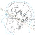
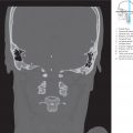
The topography of the posterior, middle, and anterior cranial fossae is best illustrated on the skull itself as spatial relationships are easily understood through a “hands-on” examination. Illustrations of the inner aspect of the base of skull in anatomic atlases may give the impression that the cranial fossae lie in the same horizontal plane. In reality, however, the three cranial fossae are arranged as three terraces, each set about 2.5 cm above or below the other.333 The floor of the middle cranial fossa lies approximately along Reid’s base line (see ▶Fig. 5.16a).179 The floor of the posterior cranial fossa lies about 2.5 cm lower and that of the anterior cranial fossa 2.5 cm higher than Reid’s base line. The sagittal series oriented in the coordinate system shows the topographic relationship of the cranial fossae to Reid’s base line most clearly in the slice where the middle cranial fossa is at its deepest (see ▶Fig. 4.11). Knowledge of these simple spatial relationships is invaluable while evaluating cross-sectional images obtained parallel to the supraorbito-suboccipital plane. The CT image of the first supraorbito-suboccipital section (see ▶Fig. 5.17a) depicts the jugular foramen in the posterior cranial fossa with the foramen spinosum, foramen ovale and the superior orbital fissure (see ▶Fig. 5.18a) being seen in the middle cranial fossa. The cribriform plate is seen within the following section (see ▶Fig. 5.18a), forming part of the anterior cranial fossa. Resting on the cribriform plate is the olfactory bulb. In this slice (see ▶Fig. 5.18b), the middle and posterior cranial fossae are enclosed by the calvarium in the form of two forceps. The internal acoustic aperture opens into the posterior cranial fossa (see ▶Fig. 5.5a and ▶Fig. 5.33). The superior orbital fissure (see ▶Fig. 4.4c and ▶Fig. 6.10a) connects the middle cranial fossa with the orbit. The dorsum sellae is not yet visualized in the center of the image (see ▶Fig. 5.18). The tentorium of cerebellum has been sectioned in the fifth slice (see ▶Fig. 5.21). The infratentorial compartment decreases gradually in size in subsequent cranial slices up to the tentorium of cerebellum. The optic canal (see ▶Fig. 5.20) is seen extending between the orbit and the middle cranial fossa (see ▶Fig. 5.36) in the fourth axial CT image. The roof of orbit is visualized in the anterior cranial fossa (see ▶Fig. 3.17 and ▶Fig. 4.11). The bony contours of the skull appear to represent an oval ring (see ▶Fig. 5.21b) from the sixth CT section onward. The infratentorial compartment is small compared to the supratentorial counterpart in the eighth CT section, with the tentorium of cerebellum forming the boundary between the two (see ▶Fig. 5.24).
7.3 Intracerebral CSF Spaces
Individual cerebrospinal fluid spaces have been described on coronal, sagittal, and bicommissural sections. ▶Fig. 7.8 indicates the position of coronal sections while ▶Fig. 7.9 illustrates the individual slices of this series. Cerebrospinal spaces are visualized on sagittal sections in ▶Fig. 7.10 (position of sagittal sections, see ▶Fig. 4.1). ▶Fig. 7.11 indicates the position of bicommissural sections, while ▶Fig. 7.12 illustrates CSF spaces in these slices.


7.3.1 Subarachnoid Space
The brain floats in a cushion of CSF due to the nearly identical specific gravity of brain substance and the cerebrospinal fluid. CSF is present within the ventricular system and the subarachnoid space. The subarachnoid space is enclosed between pia mater internally and the arachnoid mater externally and contains 25 to 50 mL of CSF.333 The arachnoid mater is closely applied to the dura, a tough fibrous membrane. Subarachnoid spaces of our anatomic preparations appear artificially enlarged due to alcohol-formalin fixation.
7.3.2 Cisterns
Widened CSF containing spaces are known as “cisterns” (see ▶Fig. 7.8a, ▶Fig. 7.9, ▶Fig. 7.10, ▶Fig. 7.11a, and ▶Fig. 7.12). The cannula enters the posterior cerebellomedullary cistern (cisterna magna) in suboccipital punctures which occupies the space between the medulla oblongata, the roof of the IVth ventricle, and the inferior surface of the cerebellum. Approximately 3 cm wide and up to 2 cm deep in the sagittal plane, the cistern is indented in the median plane by the very variable falx cerebelli.
The posterior and anterior basal cisterns are enlargements of the subarachnoid space lying between the inferior surface of the brain and the base of the skull and extend from the foramen magnum to the crista galli at the anterior edge of the anterior cranial fossa. The posterior and anterior basal cisterns are separated by the dorsum sellae.333 The pontine cistern lies between the clivus and the pons in the posterior cranial fossa, while the paired cerebellopontine cisterns lie in the region of the cerebellopontine angle. The flocculus (HX) of the cerebellum protrudes into the cerebellopontine cistern at its lateral aspect. The lateral recess of the IVth ventricle opens into this cistern through its lateral aperture, identifiable on the inferior surface of the cerebellum as the so-called “Bochdalek’s bouquet”, a protrusion of the choroid plexus of the IVth ventricle through this aperture. The superior cerebellar cistern lies between the tentorium of cerebellum and the superior surface of the cerebellum.
The interpeduncular cistern (previously: intercrural cistern) forms the anterior part of the posterior basal cistern. Coming off from the interpeduncular fossa, it contains the IIIrd cranial nerve, terminal bifurcation of the basilar artery and the origins of the superior cerebellar and the posterior cerebral arteries (see ▶Fig. 4.2d).
The ambient cistern (see Fig. 5.7) lies at the junction of the posterior and middle cranial fossae and communicates with the interpeduncular cistern. It encloses the lateral surfaces of the cerebral peduncles and forms a CSF cushion around the tentorial notch for the sharp edge of the tentorium of cerebellum. The ambient cistern passes into the quadrigeminal cistern posteriorly (great cerebral vein; see ▶Fig. 5.7 and ▶Fig. 5.23) and continues in an anterior direction to the cistern of vallecula cerebri. The quadrigeminal cistern and the cistern of the great cerebral vein were considered as synonyms by the Federative Committee on Anatomical Terminology because both describe nearly the same region between the quadrigeminal lamina and the great cerebral vein. Furthermore, the ambient cistern is connected with the unpaired pericallosal cistern and the paired interhemispheric cisterns (see ▶Fig. 3.2d and ▶Fig. 3.14d). The ambient cistern contains three blood vessels, namely the posterior cerebral artery, the superior cerebellar artery, and the basal vein (of Rosenthal) all of which direct blood posteriorly. The trochlear nerve coursing through this cistern sends its efferent signals anteriorly.
The trigeminal cistern opens into the cerebellopontine cistern (see ▶Fig. 5.20, ▶Fig. 6.8b, and ▶Fig. 6.9b) in the posterior cranial fossa. The flat, blind sac of the trigeminal cistern (see ▶Fig. 6.9b, ▶Fig. 7.9a, and ▶Fig. 7.9b) abuts on the petrous part of the temporal bone and on the sphenoid in the middle cranial fossa and houses the root of the Vth cranial nerve together with the trigeminal ganglion.
The anterior basal cistern extends from the dorsum sellae to the anterior edge of the anterior cranial fossa. It is bounded by the mammillary bodies, infundibulum, optic chiasm, optic tracts, olfactory bulbs and tracts, and the adjoining frontal lobes. A part of this cistern is the chiasmatic cistern which encloses the optic chiasm. Posteriorly, the anterior basal cistern continues into the interpeduncular cistern (see ▶Fig. 3.9a, ▶Fig. 3.9b, ▶Fig. 3.9d, ▶Fig. 5.7, and ▶Fig. 5.22). The medial part of the anterior basal cistern and the interpeduncular cistern are together called the “pentagon” (see ▶Fig. 7.12a). The circle of Willis and its central branches lie in the region of the pentagon.
The anterior basal cistern communicates laterally with the cistern of lateral cerebral fossa via the cistern of the vallecula cerebri (see ▶Fig. 5.21 and ▶Fig. 7.9a). The cistern of vallecula cerebri is a CSF-filled space between the posterior edge of the lesser wing of the sphenoid and the anterior perforated substance containing the trunk of the middle cerebral artery.
The cistern of lateral cerebral fossa (sylvian fissure; see ▶Fig. 4.6b, ▶Fig. 5.7, ▶Fig. 5.21, ▶Fig. 7.9a, ▶Fig. 7.9b, ▶Fig. 7.10b, and ▶Fig. 7.12b) forms the space between the insula and the opercular parts of the frontal, parietal, and temporal lobes.56 It is therefore also known as the insular cistern, and contains branches of the middle cerebral artery, the insular arteries.
The cistern of transverse fissure (see ▶Fig. 7.9b, ▶Fig. 7.10a, and ▶Fig. 7.11a) is a CSF cushion located in the fissure between the corpus callosum and the roof of the IIIrd ventricle including the thalamus that is between the telencephalon and diencephalon and was therefore earlier known as the “fissura telodien-cephalica”. This cistern extends anteriorly toward the interventricular foramen (of Monro; see ▶Fig. 7.8a), measuring 2.5 cm in length sagittally with a transverse diameter of 4 cm. It contains the internal cerebral veins (see ▶Fig. 5.9a) and segments of the posterior medial and posterior lateral choroidal arteries (see ▶Fig. 5.8).
The cistern of transverse fissure is in turn continuous with the quadrigeminal, pericallosal, and interhemispheric cisterns. The pericallosal cistern (see ▶Fig. 7.8a and ▶Fig. 7.10a) is the unpaired CSF-filled space between the corpus callosum and the inferior edge of the falx cerebri. The interhemispheric cisterns (see ▶Fig. 3.2d and ▶Fig. 7.9) are paired CSF spaces between the falx cerebri and the medial surface of the cerebral hemisphere on each side. The cistern of lamina terminalis (see ▶Fig. 7.9a, ▶Fig. 7.11a, and ▶Fig. 7.12b) connects the chiasmatic cistern (see ▶Fig. 7.8a, ▶Fig. 7.9a, and ▶Fig. 7.10a) with the pericallosal cistern enclosing the corpus callosum.
7.3.3 Ventricular System
The ventricular system (see ▶Fig. 7.8b, ▶Fig. 7.9, ▶Fig. 7.10, ▶Fig. 7.11, and ▶Fig. 7.12) is composed of four interconnected CSF containing spaces within the brain which exhibit great variability in shape and volume in healthy people. The mean adult ventricular volume of extracranially fixed brains is about 20 mL (between 7 and 57 mL)299 , 343 and 31 mL (between 15 and 46 mL) as evaluated on CT examinations of healthy brains.72
Fourth Ventricle
The IVth ventricle (see Fig. 3.1c, ▶Fig. 3.11b, ▶Fig. 3.11d, ▶Fig. 4.2a, ▶Fig. 4.2b, ▶Fig. 6.6a, ▶Fig. 6.8b, and ▶Fig. 7.8b) communicates with extracerebral CSF spaces through three openings:
At the obex (see ▶Fig. 4.2a, ▶Fig. 6.3, ▶Fig. 6.5b, and ▶Fig. 6.5c) through the unpaired foramen of Magendie (median aperture of the IVth ventricle).
Laterally at the medulla oblongata near the VIIIth cranial nerve through the paired foramina of Luschka (lateral apertures of the IVth ventricle; see ▶Fig. 6.7a and ▶Fig. 6.7b).
The IVth ventricle is shaped like a small tent, with the rhomboid fossa forming its floor and the superior and inferior medullary vela, cerebellar peduncles, and the cerebellum forming its roof. The inferior medullary velum is continuous caudally with the choroid plexus of the IVth ventricle suspended from a plate of connective tissue, which closes the IVth ventricle posteriorly.
Aqueduct of Midbrain
The aqueduct of the midbrain (cerebral aqueduct; see ▶Fig. 3.1c, ▶Fig. 3.10a, ▶Fig. 4.2b, ▶Fig. 5.8, ▶Fig. 5.24, ▶Fig. 7.10a, and ▶Fig. 7.12b) lies, as its name suggests, in the midbrain. Measuring approximately 15 mm in length, it is slightly curved in appearance and connects the IIIrd and IVth ventricles.
Third Ventricle
The IIIrd ventricle is an unpaired, slit-shaped space in the median plane, the walls of which are formed by the epithalamus, thalamus, and the hypothalamus from posterior to inferior. An interthalamic adhesion is present between the right and left thalami in 75% of cases. The anterior wall of the IIIrd ventricle is formed by the lamina terminalis (see ▶Fig. 3.1c, ▶Fig. 4.2a, ▶Fig. 4.2b, and ▶Fig. 5.7). A groove formed by the anterior commissure is seen at the level of the hypothalamic sulcus. Two diverticulae are seen in the region of the hypothalamus: the supra-optic recess (see ▶Fig. 7.8b) extending in the direction of the optic chiasm and the infundibular recess (see ▶Fig. 3.7a, ▶Fig. 7.10a, and ▶Fig. 7.11b) extending toward the pituitary stalk.
The choroid plexus forms the roof of the IIIrd ventricle above the interventricular foramen (of Monro). The choroid plexus is attached to the tela choroidea, connective tissue which is stretched between the medullary striae of the thalamus, and forms a diverticulum above the pineal gland, the suprapineal recess (see ▶Fig. 7.8b). A few millimeters below lies a small evagination, the pineal recess. The indentation of the habenular commissure lies above the pineal recess while the posterior commissure lies below it. The IIIrd ventricle transitions into the aqueduct of the midbrain further inferiorly.337
Lateral Ventricles
The lateral ventricles are two ram-horn shaped cavities in the telencephalon, connected to each other and with the IIIrd ventricle through the interventricular foramina. Each ventricle has four parts corresponding with four lobes of the telencephalon:
Anterior or frontal horn in the frontal lobe (see ▶Fig. 3.7a, ▶Fig. 3.7b, ▶Fig. 5.23, ▶Fig. 5.24, and ▶Fig. 7.10a).
Central part in the parietal lobe (see ▶Fig. 3.9a, ▶Fig. 3.9b, ▶Fig. 3.10a, ▶Fig. 5.11a, ▶Fig. 5.11b, and ▶Fig. 7.10a).
Posterior or occipital horn in the occipital lobe (see ▶Fig. 3.12 and ▶Fig. 7.10a).
Inferior or temporal horn in the temporal lobe (see ▶Fig. 3.9a, ▶Fig. 3.9b, ▶Fig. 4.5b, ▶Fig. 4.5d, and ▶Fig. 5.7b).
The frontal horn forms the anterior pole of the lateral ventricle up to the interventricular foramen (see ▶Fig. 3.1c, ▶Fig. 3.8a, ▶Fig. 5.1c, ▶Fig. 5.9a, ▶Fig. 5.24, ▶Fig. 7.10a, and ▶Fig. 7.11b). The frontal horn is bounded medially by the septum pellucidum and laterally by the head of the caudate nucleus, while its roof is formed by the corpus callosum.
The central part is narrow, especially due to the protruding thalamus. The floor is formed medially by the lamina affixa and laterally by the body of the caudate nucleus while the corpus callosum forms the roof. Extending through the interventricular foramen, the choroid plexus protrudes into the lateral ventricle from its medial aspect. The central part or body of the lateral ventricle extends to the splenium where it bifurcates into the temporal and occipital horns. The junction of the body, temporal horns, and occipital horns is known as the “trigone” in clinical parlance. Anatomically, the collateral trigone (see ▶Fig. 5.9a, ▶Fig. 5.9b, and ▶Fig. 5.25) is a triangular area at the beginning of the occipital horn, and is closely related topographically to the deep collateral sulcus. The roof of the occipital horn is formed by fibers of the corpus callosum, the major (occipital) forceps. A longitudinal eminence produced by the deep calcarine sulcus, the calcarine spur, is present on its medial wall.
The temporal horn curves slightly backward and laterally, with the tail of the caudate nucleus forming its roof. The amygdaloid body lies at the tip of the temporal horn (see ▶Fig. 3.8a, ▶Fig. 3.8b, ▶Fig. 4.5a, ▶Fig. 4.5b, ▶Fig. 5.6, ▶Fig. 5.7, and ▶Fig. 5.21). The choroid plexus joins the fimbria of hippocampus at the medial aspect of the temporal horn. The hippocampus lies at the mediobasal aspect of the temporal horn (see ▶Fig. 3.8a, ▶Fig. 3.8b, ▶Fig. 3.9e, ▶Fig. 4.5a, ▶Fig. 4.5b, and ▶Fig. 5.7), with its alveus bulging into this part of the ventricle (see ▶Fig. 3.9e, ▶Fig. 3.9f, ▶Fig. 5.7, and ▶Fig. 5.8).
Clinical Notes
The ventricular system and extracranial CSF spaces are important for the identification and evaluation of pathological intracranial processes despite the large interindividual and wide, age-dependent variation in their width and configuration. Lateral ventricular asymmetry, deformation of a ventricular wall or several ventricles, variable width of intra- and extracerebral cerebrospinal spaces, or a disparity in the width of the supratentorial ventricular system to that of the IVth ventricle draw the examiner’s attention to certain disease processes or aid with topical and functional diagnostic orientation: obstructive, malresorptive, hypersecretory, internal and external hydrocephalus, and hydrocephalus e vacuo.245 , 272 , 323 , 519
7.4 Cerebral Arteries and their Vascular Territories
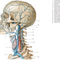
Cerebral arteries (see ▶Fig. 7.13, ▶Fig. 7.14, ▶Fig. 7.15, ▶Fig. 7.16, ▶Fig. 7.17, ▶Fig. 7.18, ▶Fig. 7.19, ▶Fig. 7.20, ▶Fig. 7.21, ▶Fig. 7.22, ▶Fig. 7.23, ▶Fig. 7.24, ▶Fig. 7.25, ▶Fig. 7.26, ▶Fig. 7.27, ▶Fig. 7.28, ▶Fig. 7.29, ▶Fig. 7.30, ▶Fig. 7.31, and ▶Fig. 7.32) are only unsatisfactorily visualized on routine CT and MR examinations, such that supplementary CTA or MRA (see ▶Fig. 7.15 and ▶Fig. 7.27) are necessary in certain situations, as in vascular diseases, differential diagnosis of tumors, and operative planning. Cerebral catheter angiography is essential in some special cases. Consequences of vascular diseases and resulting insults such as edema, infarction, bleeding, or hydrocephalus are visualized on CT and MR. Topographical anatomy of the cerebral arteries, usually derived from angiographic coronal and lateral projections, should therefore be seen in conjunction with CT and MRI findings in 3D. Thus, angiograms of the commonest arterial variations have been compared with sectional images of arteries in brain specimens.


Occlusion of large cerebral arteries (middle cerebral and basilar arteries) may be identified on CT by hyperdense segments of the arteries and by absence of flow on MRI. Territorial infarctions induced thereby may be detected on CT within 30 minutes as discreet hypodense areas and by loss of corticomedullary differentiation in the involved arterial territory. Intracranial hemorrhage is immediately detectable on CT, on MRI it can be detected in the first few hours using T2*w and FLAIR examination sequences. MRI has a higher sensitivity than CT in cerebral infarction; this is largely attributable to improved detection of infarcts in the brainstem and cerebellum. The magnitude and extent of hypodensity in CT as well as abnormal signal in MRI representing edema and infarction are determined by the size of the occluded vessel, as also by the possible collateral blood supply. Aneurysms as small as 2 to 3 mm in diameter may be detected on both CTA and MRA. Small angiomas are however not reliably identified using these methods, for the diagnosis of which DSA still remains the examination method of choice.
Exhaustive studies have been carried out in recent decades on the variability of cerebral arteries.152 , 190 , 307 , 332 , 333 , 601 The internationally accepted nomenclature has been accepted by clinicians only to some extent. Synonyms are therefore often used in literature, and it thus appears necessary to include these in brackets after internationally accepted anatomical names. Several anatomical names of cerebral arteries are more than 100 years old. A single conspicuous topographical feature was often decisive for the naming of anatomical structures.47 For instance, cerebellar arteries branch out into the cerebellum, but also give off important circumferential branches to parts of the medulla oblongata, pons, and the midbrain. Proximal occlusion of a cerebellar artery can lead to disordered functioning of the medulla oblongata, pons, or the midbrain. The name of an artery usually indicates only a part of the territory it supplies.
7.4.1 Vertebral Artery
Emerging through the transverse foramen of the atlas, the vertebral artery (see ▶Fig. 7.13 and ▶Fig. 7.20) first courses posteriorly and then bends into its sulcus situated on the atlas (see ▶Fig. 4.4c), thus forming a “reserve loop”, which allows for movements of the head. This is visualized as the V3 segment on a lateral view of the angiogram.
The artery then runs obliquely from its sulcus through the atlanto-occipital membrane, dura, and arachnoid. The atlanto-occipital sinus is located here together with the ampulloglomerular organ, which possibly represents a receptor for vascular reflexes. The vertebral artery initially follows an arcuate course, coming to lie anteriorly to the medulla oblongata (see ▶Fig. 3.9c, ▶Fig. 3.10c, ▶Fig. 4.2c, and ▶Fig. 5.3). Its intracranial course is termed the V4 segment (see ▶Fig. 7.13b). The left and right vertebral arteries fuse to form the basilar artery usually at the inferior margin of the pons (in 66% of cases), rarely at the level of the anterior part of the medulla oblongata. The right or left vertebral artery may exhibit a larger lumen or may form a loop in its V4 segment.
The anterior spinal artery and the posterior inferior cerebellar artery (PICA) are angiographically demonstrable branches of the vertebral artery. The anterior spinal artery arises from the vertebral artery immediately proximal to its union with the contralateral artery and then runs in an inferomedial direction. In 77% of cases, the right and left arteries form an unpaired median anterior spinal artery approximately 2 to 3 cm from their origin.333 The anterior spinal artery is unilaterally absent in 20% of cases, while it does not unite with its counterpart in another 13%. Paramedian branches from the anterior spinal artery supply the medulla oblongata.
The PICA (see ▶Fig. 3.10c, ▶Fig. 4.2c, ▶Fig. 4.3c, ▶Fig. 4.3d, ▶Fig. 5.3a, ▶Fig. 7.13, and ▶Fig. 7.14a) usually arises intracranially from the vertebral artery, originating caudal to the foramen magnum in 18% of individuals, while in another 10% it arises from the basilar artery. The PICA is unilaterally absent in 10% of cases, while bilateral absence has been noted in 2%. This cerebellar artery follows a very variable course along the lateral edge of the medulla oblongata.307 , 333 Fine branches pass from this vessel to the anterolateral, lateral, and parts of the posterior territories of the medulla oblongata, where the nucleus ambiguus and other structures, including the central sympathetic pathway, spinal nucleus of the trigeminal nerve, and the spinothalamic tract are located (see ▶Fig. 6.4b, ▶Fig. 6.5b, and ▶Fig. 6.6b). Thereafter, the artery may form a vascular loop on or around the tonsils of cerebellum. This vascular sling lies caudal to the foramen magnum in 18% of individuals, so an inference of brain edema with caudal displacement of the tonsils of cerebellum cannot be made with certainty in such cases. A branch of this cerebellar artery extends into the choroid plexus of the IVth ventricle. The terminal segment of the PICA courses over the inferior surface of the cerebellum and branches into two: a medial branch that supplies the inferior surface of the vermis and a lateral branch that supplies the inferior surface of the cerebellar hemisphere, including a small part of the dentate nucleus.
7.4.2 Basilar Artery
The basilar artery is formed by the union of the vertebral arteries (see ▶Fig. 3.8b, ▶Fig. 3.8c, ▶Fig. 4.2c, ▶Fig. 4.2d, ▶Fig. 5.5, ▶Fig. 5.6, ▶Fig. 5.20, and ▶Fig. 7.14) and traverses the basilar sulcus of the pons within the pontine cistern, passing superiorly to the interpeduncular cistern. It measures 32 mm in length on an average (15–40 mm). In 51% of cases the superior end of the basilar artery is seen lying at the level of the dorsum sellae, in 30% above it, and in 19% below it.307 The artery forms a right or left concave arch in 10% of cases, usually together with a wider contralateral vertebral artery, assumed to be the result of hemodynamic factors.234 This curved course is not to be confused with pathologic displacement due to a space-occupying lesion.
Branches of the Basilar Artery (see ▶Fig. 7.14 and ▶Fig. 7.15):
Pontine arteries (fine branches, not sectioned)
Anterior inferior cerebellar artery (AICA) (see ▶Fig. 4.2c, ▶Fig. 4.4c, ▶Fig. 5.5, and ▶Fig. 7.14a)
Superior cerebellar artery (see ▶Fig. 3.8c, ▶Fig. 4.2c, ▶Fig. 4.2d, ▶Fig. 5.6, ▶Fig. 6.11b, ▶Fig. 7.13a, and ▶Fig. 7.14a)
Posterior cerebral artery (see ▶Fig. 3.8c, ▶Fig. 4.2c, ▶Fig. 4.2d, ▶Fig. 5.6, ▶Fig. 6.13b, ▶Fig. 7.13a, and ▶Fig. 7.14a)
The pontine arteries, usually about eight in number, arise almost at right angles from the basilar artery. Their medial branches supply the anteromedial, their lateral branches the anterolateral and lateral territories of the pons. Pontine arteries are generally not seen on angiograms.
The AICA originates in 52% of cases from the inferior third of the basilar artery, while in 46% it arises from the middle third and in 2% from the upper third of the basilar artery. In exceptional cases the AICA may arise from the vertebral artery. A unilateral duplication of the AICA is present in 10% of cases; unilateral absence is noted in 1% while bilateral absence is present only rarely. The first part of the AICA usually extends inferolaterally over the pons (see ▶Fig. 7.14a) where it gives off a few fine branches, and then forms a sling from which the labyrinthine artery arises in approximately 70% of individuals. In the remaining instances, the labyrinthine artery arises directly from the basilar artery. The AICA either crosses the flocculus (H X) or encircles it, supplying it with fine branches. Additional fine branches extend from this floccular part of the artery into the middle cerebellar peduncle of the pons and to the medulla oblongata. The hemispheric branches of the AICA supply the inferior surface of the cerebellum as well as the choroid plexus of the IVth ventricle.
The superior cerebellar artery is the most constant cerebellar artery, arising from the basilar artery immediately proximal its terminal bifurcation (see ▶Fig. 7.14a and ▶Fig. 7.15).
In about 4% of cases, this cerebellar artery arises from the posterior cerebral artery332 and is bilaterally duplicated in about 10%. The superior cerebellar artery gives off fine branches to the posterior territory of the pons and partly to the posterior territory of the midbrain, as well as wider branches which supply the superior surface of the cerebellum (see ▶Fig. 7.13b).
Cerebellar arteries anastomose with each other. The remaining cerebellar arteries may partially or completely compensate for the absence of anlage of one cerebellar artery. With an absent PICA, for instance, the AICA and the superior cerebellar artery take over the blood supply of the inferior surface of the cerebellum. A single PICA independently supplies the inferior surface of the cerebellum in 60% of cases and is supplemented by the AICA in 26% and by the superior cerebellar artery in 3% of cases. The superior surface of the cerebellum, on the other hand, is supplied in 67% of cases by the superior cerebellar artery, supplemented chiefly by the AICA and the PICA.333
7.4.3 Posterior Cerebral Artery
The posterior cerebral artery (see ▶Fig. 7.16; see also ▶Fig. 3.8c, ▶Fig. 4.2c, ▶Fig. 4.3c, ▶Fig. 5.6a, ▶Fig. 5.6b, ▶Fig. 7.14a, ▶Fig. 7.15, and ▶Fig. 7.22a) arises as the terminal bifurcation of the basilar artery in about 90% of cases and extends into the interpeduncular cistern between the cerebral peduncles and the clivus (see ▶Fig. 5.7a). A fetal type is present in the remaining 10%, whereby the posterior cerebral artery continues as an extension of the posterior communicating artery and is thus a branch of the internal carotid artery.
The segment of the posterior cerebral artery between the basilar and the posterior communicating arteries is referred to as the precommunicating part or “P1 segment” and measures 6 mm in length on an average (3–9 mm). Small penetrating branches of the precommunicating part (posteromedial and posterolateral central arteries; see ▶Fig. 6.12b and ▶Fig. 7.16) penetrate the anterior perforating substance to partially supply the midbrain and diencephalon. These fine arterial branches are seldom visualized on angiograms.332
The postcommunicating part of the posterior cerebral artery arches around the midbrain and lies in the ambient cistern. Small penetrating arteries (posterolateral central arteries [see ▶Fig. 7.16] and the collicular artery) arising from this postcommunicating segment supply posterior parts of the thalamus (see ▶Fig. 7.17), tectum of the midbrain and the pineal gland.
The posterior cerebral artery divides into its two main branches inferior to the pulvinar and superior to the tentorium of cerebellum:
Medial occipital artery (previously: internal occipital artery; see ▶Fig. 3.10c, ▶Fig. 4.3c, ▶Fig. 5.7, ▶Fig. 5.8, ▶Fig. 7.14b, and ▶Fig. 7.22a)
Lateral occipital artery (previously: temporo-occipital or occipitotemporal artery; ▶Fig. 3.10c, ▶Fig. 3.10d, ▶Fig. 4.4c, ▶Fig. 5.8a, and ▶Fig. 7.14b)
The posterior medial and posterior lateral choroidal arteries arise from the proximal aspect of the postcommunicating part of the posterior cerebral artery (see ▶Fig. 7.17; see also ▶Fig. 5.8 and ▶Fig. 7.16). Running between the quadrigeminal plate and the parahippocampal gyrus, they supply the choroid plexus of the IIIrd and lateral ventricles. In addition, fine branches run to the pineal gland, quadrigeminal plate and to other parts of the diencephalon. Several branches supply the lateral and medial geniculate bodies, the posterior aspect of the thalamus, and the parahippocampal gyrus. Between one and four branches of the parahippocampal arteries supply the parahippocampal gyrus, the hippocampal formation, and parts of the splenium of the corpus callosum. Branches of parahippocampal arteries may be strangulated by the tentorium of cerebellum in patients with cerebral edema, usually resulting in degeneration of Sommer’s sector corresponding approximately to the H1 field360 of the hippocampal formation. Additional cortical branches supply the inferior aspect of the temporal lobe.
The division of the posterior cerebral artery into two approximately equal main branches usually occurs at the lateral aspect of the cerebral peduncle (see ▶Fig. 7.13b and ▶Fig. 7.16). This division is usually a bifurcation, sometimes a trifurcation, and very rarely a quadrifurcation.332 Coursing over the posterior aspect of the parahippocampal gyrus, the lateral occipital artery supplies the inferior surface of the occipital lobe. The medial occipital artery runs beneath the splenium of the corpus callosum and crosses the isthmus of the cingulate gyrus, dividing into its terminal branches, the parieto-occipital and calcarine arteries. The parieto-occipital artery (see ▶Fig. 3.13c, ▶Fig. 4.2c, ▶Fig. 4.4c, ▶Fig. 5.10a, and ▶Fig. 7.16) runs, for the most part, in the sulcus of the same name, supplying the cuneus and precuneus. The calcarine artery (see Fig. 3.13c, ▶Fig. 4.2c, ▶Fig. 4.4c, ▶Fig. 4.4d, ▶Fig. 5.10a, ▶Fig. 5.10b, and ▶Fig. 7.16) lies on or in the calcarine sulcus and seldom arises from the lateral occipital artery. The calcarine artery supplies entirely the area striata or the primary visual cortex only in about one-fourth of cases,546 while in the remainder, the visual cortex is partially supplied by neighboring arteries. Vascular occlusions of the calcarine artery can give rise to a homonymous hemianopia with macular sparing when a neighboring artery adequately supplies that part of the area striata near the superior cerebral margin which has a one-on-one connection with the macula lutea.
Related posts:

Stay updated, free articles. Join our Telegram channel

Full access? Get Clinical Tree


