Particle Accelerators
Jay Flanz
INTRODUCTION TO THE PHYSICS OF PARTICLE ACCELERATORS
Particle accelerators increase the kinetic energy of charged particles. For the purposes of particle therapy, this increase is equivalent to an increase of the range of penetration in a patient. The Lorentz force laws, 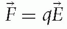 and
and 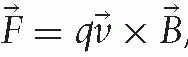 , describe the physical processes of acceleration. The first explains that an electric field E produces a force F on a particle with charge q that accelerates the particle along the direction of the field E. The second explains that a charged particle with velocity v in a magnetic field B experiences a force F perpendicular to the direction of motion and the magnetic field. Thus, an electric field increases the particle’s energy and a magnetic field describes its motion.
and , describe the physical processes of acceleration. The first explains that an electric field E produces a force F on a particle with charge q that accelerates the particle along the direction of the field E. The second explains that a charged particle with velocity v in a magnetic field B experiences a force F perpendicular to the direction of motion and the magnetic field. Thus, an electric field increases the particle’s energy and a magnetic field describes its motion.The technology of delivering a charged particle of the appropriate energy to a patient involves accelerating, bending, and focusing a beam of particles in the direction of the target in the patient. A beam of particles is a collection of particles within a small range of position, angle and velocity. Most of the particles in the beam, depending on the overall system, arrive at the target.
PARTICLE ACCELERATORS FOR THERAPY FACILITIES
An accelerator acceptable for particle therapy in a clinical environment must satisfy at least some of the following constraints. The beam parameters obtained from the accelerator must satisfy the clinical beam requirements for desired treatments. There is no qualification for this requirement! The requirements depend upon the clinical use of the facility, which in turn depend upon the treatment sites and modalities chosen by the physicians. The overall system availability must be >95%. The accelerator is just one of many components and therefore its availability should be >99%. One may even ask the question whether it could be cost effective to have more than one accelerator at one facility or one accelerator per treatment room. This partly depends upon the number of treatment rooms that must be serviced, but can depend upon the cost of downtime in terms of lost revenue and maintenance costs. The overall system must be compact enough to fit in a clinical building. Generally this implies a space <8 m across (depending upon the venue). As the applications of particle therapy expand, however, facilities with more treatment rooms are needed and being built, and in those facilities a larger accelerator does not add significantly to the overall size or cost. On the other hand, some medical facilities do not have the space or the need for multiple treatment rooms. Designs for small accelerators are, therefore, being actively pursued. The accelerator must be easy to operate. The number of staff to operate and maintain this equipment in a hospital environment cannot be at the same level as those in a physics laboratory environment. Of course, “easy” is relative and depends upon staff training.
IMPACT OF CLINICAL USE ON ACCELERATOR REQUIREMENTS
It is important to ensure that the accelerator is optimized for production of the desired clinical beams and delivery modalities. The type of beam delivery modality can determine the beam requirements. In the pencil beam scanning modality, the unmodified beam is dynamically positioned within the target. The beam parameters and target thereby uniquely determine the clinical parameters. If additional materials are in the beam path to manipulate the beam, for example, spread it out or diffuse its energy, then the accelerator beam parameters might need to be adjusted for the appropriate clinical beam.
Clinical parameters such as dose rate, range, distal fall-off, and lateral penumbra are directly affected by the beam current, beam energy, the beam energy spread, and the beam size, respectively. In addition the parameters are affected by material in the beam. Devices that fully intercept the beam reduce the range and increase the distal fall-off and lateral penumbra. Devices that partially intercept the beam can be used to sharpen the lateral penumbra. If one uses double scattering to spread out the beam, then a proton beam of energies between 230 and 270 MeV, corresponding to 33- to 43-cm range in water, is required.1 Intensity-modulated particle therapy, IMPT, is the modality of choice and most facilities are beginning to incorporate this technique. For this technique, in addition to the usual parameters such as energy and current, it is important to consider the accelerator beam macro time structure, and dynamic parameters such as the time rate of change in energy, dE/dt, current, dI/dt and position, dx/dt, respectively.
TYPES OF ACCELERATORS
Accelerators are devices that control an electric field in such a way as to efficiently accelerate the charged particle. A linear accelerator (LINAC) controls the electric field to accelerate a beam in a linear path, and therefore the LINAC length is proportional to the strength of the electric field and the gain in energy. Conventional linear accelerators do not produce sufficient electric field strength to build a compact system for heavy charged particles although nonconventional techniques (e.g., dielectric wall) are being investigated.
In order to accelerate charged particles in a compact machine, it is efficient to reuse the electric field. Therefore, circular machines such as a cyclotron or a synchrotron are used that repeatedly steer the particle beam across the same electric field. In general, due to the energy required for clinical use, these accelerators are still large. They therefore remain separate entities and feed beamlines, which transport the beam to treatment rooms. New methods are being developed which may allow one accelerator per treatment room, as is the case for conventional electron LINACs. The economics, however, of duplicating the currently single accelerator that feeds multiple rooms to one per room are yet to be proved. Typically, the dose delivery portion of a treatment should last approximately 1 to 2 minutes to minimize the impact on a patient. The time during which the patient occupies the room depends upon the operation of a particular clinic, but usually includes in-room patient alignment which takes several minutes. In this case, the accelerator usage is a small fraction of the required treatment room time. Therefore for maximal use of the expensive accelerator, it could be more economical to deliver beam to several rooms.
The Cyclotron
The charged particle beam trajectory in a simple cyclotron is shown in Figure 4.1. A simple cyclotron can be visualized as a vertically divided pillbox. An electric field is applied across the gap between the two halves, called dees for their resemblance to the letter, and a magnetic dipole field covers both dees. The beam is injected into the center of the cyclotron and accelerated each time when it crosses the electric field. When the beam leaves the electric field region, it enters the magnetic field region and is bent 180 degrees, and reenters the electric field region at the correct time to be accelerated in the opposite direction. The polarity of the electric field is switched at the exact time when the beam reaches the gap to ensure acceleration, and not deceleration, of the beam. The radiofrequency (RF) of the electric field, needed to synchronize the path of the charged particle with the phase of the electric field, is given by the cyclotron equation ω = qB/m, where ω is the angular frequency of the electric field, q is the charge of the particle, m is the mass of the particle and B is the magnetic field of the cyclotron magnet. Since the magnet field is nearly constant, the radius of the trajectory increases with energy; the effective trajectory therefore resembles a spiral. The particle is extracted from the edge of the cyclotron where the beam has reached its maximum energy and is directed to the treatment room.
The size and weight of a cyclotron is primarily determined by the strength of its magnetic field, or more specifically the size and therefore the weight of the iron and copper required to achieve the necessary magnetic field.
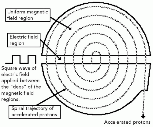 Figure 4.1 Pictorial description of the beam and electric and magnetic fields in a cyclotron. The electric field between the gap of the cyclotron dees accelerates the protons at every gap crossing. The magnetic field confines the beam within the D volumes until the beam reaches the maximum energy at the edge of the cyclotron and is extracted. |
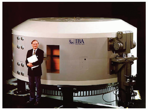 Figure 4.2 The C230 cyclotron from the IBA corporation, Belgium. Courtesy of IBA LTD, Louvain la Neuve, Belgium. |
The C230 cyclotron built by Ion Beam Applications S.A. (Louvain la Neuve, Belgium) is shown in Figure 4.2. It is a room-temperature cyclotron with a magnetic field as high as 3 Tesla in some places.2 Extracted currents higher than 300 nA are possible. The overall weight of the iron core and the copper coils is 220 tons and stands in a footprint of a diameter of 4 m. The cyclotron opens along the horizontal median and allows for maintenance, which is an important maintenance feature to achieve the required availability. The first such cyclotron was constructed for the Francis H. Burr Proton Therapy Facility at the Massachusetts General Hospital in Boston, MA and became operational in 1997.
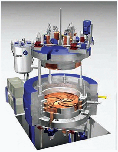 Figure 4.3 The Comet cyclotron from the ACCEL corporation, Germany. Courtesy of the Accel Instruments GmbH, Bergisch Gladbach, Germany.
Related posts:Stay updated, free articles. Join our Telegram channel
Full access? Get Clinical Tree
 Get Clinical Tree app for offline access

|