Patient Positioning and Set-up Verification for Planning and Treatment
Martijn Engelsman
Alejandro Mazal
David A. Jaffray
The last 10 years have seen a significant effort in the field of radiation therapy to characterize the geometric uncertainties in targeting radiation therapy. The advent of conformal radiation therapy techniques, computed tomography (CT) simulation, and three-dimensional (3-D) treatment planning has sensitized the community to the significant technical challenges associated with the accurate and precise placement of radiation with respect to soft tissue structures within the human body. The developments of dosimetric and geometric standards for dose prescription1,2 have provided great service not only in standardizing radiation delivery, but also through the creation of a standardized lexicon for discussion of the geometric challenges. These include separation of image-based targets (gross tumor volume, GTV), clinical understanding of microscopic extent and regional spread (clinical target volume, CTV), and a volume to which the plan is directed to assure coverage of the CTV (planning target volume, PTV). The extension of the CTV to the PTV is achieved through a geometric margin of expansion. This margin is to be constructed from estimates of the uncertainty in placement of the radiation with respect to the target. The development of margin recipes based on two-parameter characterization of this geometric uncertainty has been an important contribution to the field. Geometric errors in patient setup and organ position can be fairly well characterized by a distribution with nonzero mean (systematic) and some distribution (random) components;3,4 see Table 7.1 for typical values as assessed from photon radiotherapy. This model is quite general and has been applied to characterize geometric errors in many radiation therapy studies. The need for more complex descriptions, such as, time-dependent trends has not proved to be necessary to date; intratherapeutic imaging, however, is likely to provide evidence of this in the future.5 These types of trended distributions, or even more complex motions such as deformation, will be more difficult to accommodate through simple margin-based approaches and will likely require replanning events, or so-called adaptive radiation therapy.6 These concepts and formalisms, except perhaps for the conversion of geometric errors into a PTV margin, apply equally well, or even more, to heavy charged particle therapy as they do in photon or electron therapy. The conversion to PTV depends critically on the physical, as opposed to solely the geometric, properties of the field. Therefore, the vast literature of data on geometric uncertainties established in conventional external beam is of similar value to charged particle
radiotherapy. The additional challenges of path-length consistency in particle therapy, a dimension in patient positioning not present in photon radiotherapy, raise a new challenge for the image-guided particle therapy (IGPT) paradigm. This should be a consideration in designing an image-guidance system for heavy charged particles.
radiotherapy. The additional challenges of path-length consistency in particle therapy, a dimension in patient positioning not present in photon radiotherapy, raise a new challenge for the image-guided particle therapy (IGPT) paradigm. This should be a consideration in designing an image-guidance system for heavy charged particles.
TABLE 7.1 ESTIMATES OF TYPICAL VALUES OF TARGET MOTION IN RADIOTHERAPY | ||||||||||||||||||
|---|---|---|---|---|---|---|---|---|---|---|---|---|---|---|---|---|---|---|
| ||||||||||||||||||
ISSUES OF UNCERTAINTY AND POSITIONING
The accuracy of patient positioning in external radiotherapy is based, in general, on a set of methods and materials including multimodality image acquisition, a patient positioner, patient immobilization devices, patient position verification systems and the beam delivery system. Setup correction protocols may be employed to limit the therapist workload as well as the (radiation) burden to the patient. In contrast to photon radiotherapy, however, online patient position verification and correction is the standard in heavy charged particle therapy, often going so far as to verify patient position not only after initial patient setup, but before every field within in a treatment fraction. Critical structures are presumably best spared, and tumor coverage best guaranteed, if radiation delivery is based on the most recent imaging information, although intrafractional patient motion may subsequently change the patient position. The rationale behind always using the most recent information available is the aim of heavy charged particle therapy to perform radiotherapy with the highest accuracy and precision possible.
Chronologically, patient positioning-related work in the treatment room consists of (a) patient immobilization, (b) patient prepositioning, (c) patient setup verification, and (d) patient repositioning. Patient positioners play a role in both step b and step d and will be discussed after patient immobilization.
PATIENT IMMOBILIZATION
The aim of patient immobilization is to minimize the impact of patient motion during treatment, which limits the accuracy of radiation treatment. Immobilization devices must therefore be rigid, while being comfortable enough for the patient over an entire treatment fraction. An additional benefit of immobilization devices is that they may allow for fast and accurate patient setup in the treatment room depending on the reproducibility of the patient position within the immobilization device, and of the device with respect to the treatment beam.
Many of the principles of patient immobilization as used in photon radiotherapy apply to heavy charged particle therapy as well. For example, immobilization devices should be easy to adjust to patient-specific geometries, portable so they can be used both at diagnostic locations and in the treatment room, and they should exhibit minimal distortion in the CT scans acquired for treatment planning.
Some significant differences with photon radiotherapy exist. Owing to the physical properties of heavy charged particles, there is no build-up effect on the patient skin. This allows for the use of immobilization material in contact with the patient skin. The most important difference is, however, that heavy charged particle beams are highly sensitive to changes in radiologic depth because of the sharp dose gradient at the distal edge of the (spread-out) Bragg peak. Thickness gradients in immobilization devices that intersect the ion beam trajectory should therefore be kept to a minimum. The use of carbon composites facilitates this aim.11
Furthermore, the use of immobilization devices may influence the lateral dose gradient. The lateral dose gradient is a function of the radial emittance of the charged particle beam. This effect can be quite accurately modeled by dose calculation algorithms12 (see Eq. 7.1).
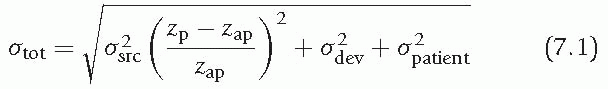
where σtot is the total radial emittance, σsrc the radial emittance of the (virtual) source, and σdev and σpatient the increase in radial emittance due to scattering in devices downstream of the aperture and within the patient, respectively. The parameters zp and zap are the distance from the point of interest and the beam limiting device to the source position, respectively.
According to Eq. 7.1, both an increase in radiologic thickness of material between the beam source and the target volume, and an increase in the distance between the aperture and the patient, will increase the lateral beam penumbra.13 Immobilization devices should
therefore be radiologically and geometrically thin to have maximum dose conformality and sparing of organs at risk laterally to the beam direction. Especially in the case of passive-scattered beams for which apertures and range compensators are used, the immobilization device should not interfere with the bulkiness of the treatment nozzle. Irradiation through the treatment couch also leads to an increase in lateral dose falloff in the patient because it increases the distance between the beam limiting device and the target, while the couch materials scatter the beam, albeit slightly.
therefore be radiologically and geometrically thin to have maximum dose conformality and sparing of organs at risk laterally to the beam direction. Especially in the case of passive-scattered beams for which apertures and range compensators are used, the immobilization device should not interfere with the bulkiness of the treatment nozzle. Irradiation through the treatment couch also leads to an increase in lateral dose falloff in the patient because it increases the distance between the beam limiting device and the target, while the couch materials scatter the beam, albeit slightly.
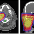
 Figure 7.1 Immobilization devices for tumors of (A) base of skull, (B) neck/cervical spine, and (C) paranasal sinus. |
The treatment couch thickness reduces the range of the ion beam, and the prescribed range, as obtained in the treatment planning system (and assuming the couch was not included in the plan), needs to be increased by this thickness. The field monitor units are determined from the actual range including this thickness, that is, the couch thickness does not simply introduce an “attenuation” factor but affects the overall dosimetry instead.
Generally, commercially available immobilization devices do not meet all requirements of heavy charged particle therapy, and ion therapy facilities either modify existing devices or design their own. Some examples are shown in Figure 7.1. The devices shown in Figure 7.1A and 7.1B are especially designed to allow for close proximity of an aperture to the patient, thereby minimizing the lateral dose falloff in the patient. Because of the high degree of immobilization pursued in charged particle radiotherapy, two methods of immobilization can be combined, such as an intracranial mask and a bite-block (see Figure 7.1C).
Historically, due to the limited range penetration of the available ion beams, charged particle radiotherapy was frequently applied to tumors in the head and neck region. The required immobilization accuracy for these anatomic sites is very high because of the many critical organs in close proximity to any skull-based tumor. Despite the fact that the skull is relatively easy to immobilize because of almost direct contact between the device and bony anatomy, many immobilization devices that have been developed can only limit intrafractional patient motion to the order of 3 to 4 mm, 3-D vector length.8 Only the noninvasive stereotactically applied Gill-Thomas-Cosman frame maintains patient position to within 2 mm.8,14 Immobilization devices for the chest region, pelvic region, or extremities, such as the alpha-cradle, leg abductor, or beanbag, are much less motion limiting. They are also
bulky and limit the choice of beam directions or at least the proximity of an aperture and range compensator to the patient. The close placement of these devices is necessary, at least in double-scattering methods, to maintain as sharp a lateral falloff as possible (Eq. 7.1).
bulky and limit the choice of beam directions or at least the proximity of an aperture and range compensator to the patient. The close placement of these devices is necessary, at least in double-scattering methods, to maintain as sharp a lateral falloff as possible (Eq. 7.1).
Additional requirements of immobilization devices may apply for treatment setups in which the patient rotates around a fixed beam line instead of a gantry rotating around the patient, for example an increased lateral support. For scanned beams, some of the arguments discussed in this section do not apply because no field specific hardware (i.e., range compensator and aperture) is required. Immobilization and knowledge of the tumor position during treatment is, however, even more important due to interference effects between the scanning beam and moving tumor.
PATIENT POSITIONERS
Heavy charged particle radiotherapy, especially in the head and neck region, is characterized by the use of stringent safety margins around the target volume, with often steep dose gradients close to critical structures. The aim of heavy charged particle therapy to treat with the highest accuracy possible translates into a distinct difference with “classical” radiotherapy, regarding patient positioning systems (PPSs). PPSs for heavy charged particle therapy, either couches or robotic arms, tend to have 6 degrees of freedom to allow for maximum accuracy and precision in reproducing the patient and target position with respect to the incident beam. Robots are readily available and used for industrial purposes and can be adapted for this, and other, applications in radiotherapy.
Conventional positioners to set up patients associated with a conventional treatment device or a simulation device are based on couches with 4 degrees of freedom (three linear orthogonal translations and one rotation around a vertical axis), and in some cases with an additional rotation of the final table top, also around a vertical axis. The reproducibility and the accuracy of these positioning systems are in the order of 1 to 2 mm and 1 to 2 degrees, but larger tolerances also exist in clinical practice. Patient positioners are usually associated with patient immobilization systems (frames, masks, foams), and room or beam reference coordinates in space given by light and laser beams pointing to specific skin marks.
Modern approaches use x-ray views and/or portal images to compare radiologic views with virtual simulations of the treatment position, using anatomic or implanted fiducial landmarks. Other methods are applied for specific cases (e.g., ultrasonography for prostate location, positron emission tomography [PET] images for carbon ion therapy), including dynamic measurements of internal or external signals to minimize and synchronize or track the movement of a target volume during treatment.
The need for higher accuracy (submillimeter and <1 degree) and additional degrees of freedom (tilt and roll) for the patient positioner in specific applications such as stereotactic radiosurgery and proton radiotherapy led different teams to develop special devices, some of which will be discussed in this section before providing some general requirements regarding robotic positioners.
Seated Patient Position and Fixed Beam Lines
The use of fixed beam lines, that is, no isocentric gantry or movable beam, in the pioneering centers for proton therapy imposed additional requirements on the patient positioner, as the patient movement was the only free parameter available to change beam directions with respect to the patient and to correct the setup. The general approach in radiation oncology was, and still is, to keep the patient supine for image acquisition, simulation, and treatment. For particle therapy, however, in the specific cases of irradiation of clinical targets in the head and neck region (i.e., ocular, intracranial, and base of the skull targets) the first approach was to adopt a seated position for the treatment so as to fully employ a fixed horizontal line.
Related posts:


Stay updated, free articles. Join our Telegram channel

Full access? Get Clinical Tree


