Chapter 10 Pelvis and hips
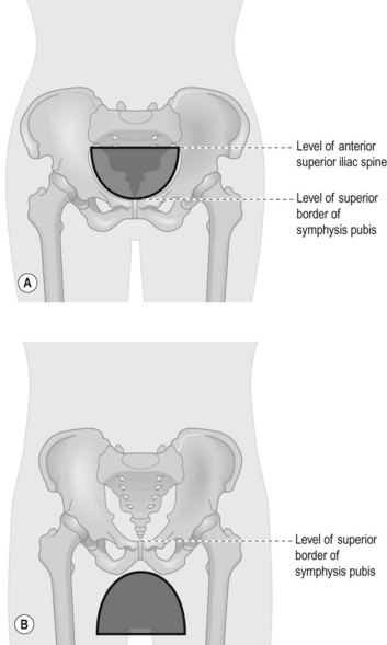
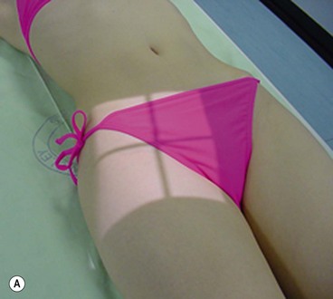
Radiographic examination of the pelvis and hips must be undertaken with care as the region surrounds the radiosensitive reproductive organs. Gonad protection should be used in most cases and should be correctly positioned (Fig. 10.1A,B); an exception is made when examining the female pelvis in trauma, for an initial examination of a child, or when there is a non-specific region of pain in the first examination. The 28-day rule should always be used in women of reproductive capacity when examining this area.
Indication
The pelvis and hips may be examined for the following reasons:
Osteoarthritis
The hip joints may degenerate in this condition, but radiographic examination should only be performed if the patient is likely to require hip replacement.1
Perthes’
A disorder of the upper femoral epiphysis, this manifests as osteonecrosis of the capital femoral epiphysis.2 This is where the growing epiphysis shows ischaemic changes. It presents most commonly in children aged 4–9 years, and boys are four times more likely to be affected than girls.3
Anteroposterior (AP) pelvis and hips (Fig. 10.2A,B,C)
There are two methods for producing the AP pelvis: the first demonstrates the full pelvis and hip joints, the second is required for hips only. This second projection is usually requested for follow-up after hip replacement surgery and may be referred to as a ‘low centred’ pelvis. However, it is a valid and recognised projection, having been described in texts for many years.4–7 Radiographers should not, therefore, assume that this is simply a ‘mis-centred pelvis’ and consider it to be a suboptimal procedure. Field size is as for the pelvis and hips AP, as it is often necessary to include a longer section of the femur to ensure the whole length of hip prosthesis is demonstrated (if relevant).
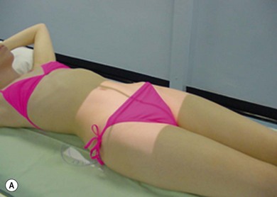

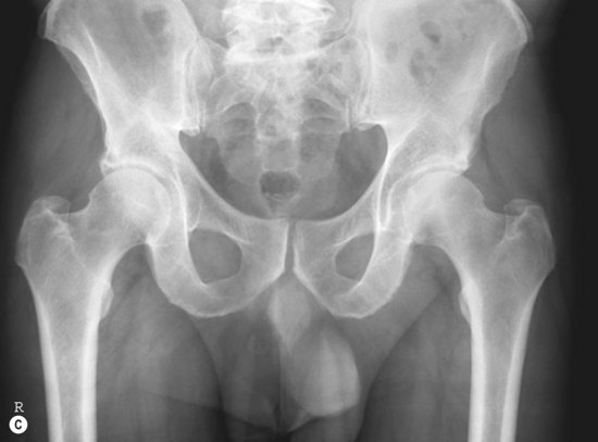
Figure 10.2 (A) AP position – pelvis and hips. (B) AP pelvis and hips; (C) centring the AP pelvis for hips.
IR is horizontal, employed with antiscatter grid (for adults).
Positioning
• The patient lies supine on the table with their legs extended and their head resting on a pillow
• The median sagittal plane (MSP) is at 90° to the table-top and the anterior superior iliac spines (ASISs) should be equal distance from the table-top
• The arms are raised onto the pillow
• The legs are slightly internally rotated to bring the necks of femora parallel to the table-top
• Gonad protection is applied if appropriate. Exceptions are when examining the female pelvis in trauma, for a first examination of a child, or when there is a non-specific region of pain in the first examination
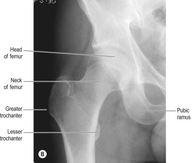
For this projection both feet are internally rotated slightly during positioning to bring them into the true anatomical position and allow the neck of femur (NOF) to lie parallel to the image receptor (IR).4,7 This facilitates demonstration of the femoral neck with minimal foreshortening, and also clears the greater trochanter from the femoral neck, the lesser trochanter appearing in profile medially. If the feet are excessively internally rotated the lesser trochanter will be obscured and if they are externally rotated, or even if the toes point in an upwards and vertical direction, the NOF will appear foreshortened on the resulting image, with the greater trochanter superimposed over the neck.4,7
In the case of trauma, foot position can provide an indication of a fractured NOF. The patient will present with the affected leg in noticeable external rotation, often with the lateral aspect of the foot in contact with the trolley top and apparent shortening of the leg. No attempt must be made to move or internally rotate this leg.2
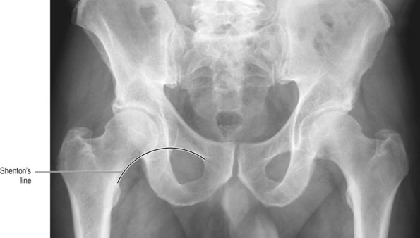
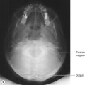
A line known as Shenton’s line (Fig. 10.3) follows the curve of the upper border of the obturator foramen and continues to travel inferiorly down the medial border of the femoral neck. This line can be used as a guide to compare the two sides when checking for injury, as a disruption in the normally smooth, curved line indicates subluxation, dislocation or change in femoral neck position as a result of fracture.
Overexposure of the greater trochanters can be a problem in this projection, particularly in thin patients who have little soft tissue in this region. This can be resolved by careful consideration of exposure factors: a reduction in mAs will reduce the degree of image blackening, and to cater for this a kVp of at least 70 will reduce the level of subject contrast.4,7 It is suggested that a minimum of 70 kVp be used in all AP pelvis examinations.
Collimation
For the pelvis and hips: iliac crests, proximal portion of femora, greater and lesser trochanters
The IR may be aligned with the X-ray beam before examining the patient and, as originally suggested by Unett and Royle4 and later by others,7 collimation can be adjusted at this point. This avoids the temptation to open the collimators wider than necessary when X-raying a larger than average patient.
Criteria for assessing image quality
• Iliac crests and greater and lesser trochanters are demonstrated for full pelvis, acetabulae, trochanters and appropriate amount of femur for the hips only
• Iliac bones, heads and necks of femora and the greater and lesser trochanters and obturator foramina should be symmetrical
• Sharp image demonstrating the range of densities of the bony cortex and trabeculae of the pelvis and its soft tissues, hips and trochanters
| Common errors | Possible reasons |
|---|---|
| Asymmetry of structures | MSP not 90° to table-top (rotated patient). This could be due to muscular atrophy or simply the patient lying awkwardly. Use of radiolucent pads may help correct this in the case of muscular atrophy. The notable features in the pelvis are the obturator foraminae and iliac bones; study of a rotated pelvis image will show a larger obtutator foramen (compared with the other obturator foramen) and narrowed ilium on the side that is raised from the table |
| Greater trochanters obscured and overlying the NOF | Feet are not internally rotated (this is unavoidable in patients with fractured NOF) |
| Overexposed image (see section after positioning, for overexposure of the greater trochanters and uneven exposure of hips and pelvis) | If an automatic exposure device (AED) has been used for a patient with hip prostheses the exposure will continue for longer than necessary to try to expose the hips correctly. There are other problems associated with AED use (see comments after the positioning section for the pelvis). Setting a manual exposure is a suitable solution in both events described here |
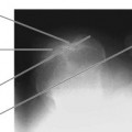
AP single hip (Fig. 10.4A,B)
IR is horizontal, used with antiscatter grid
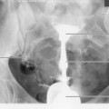
Centring point
The femoral pulse (and therefore the centre of the head of femur) is located thus: draw an imaginary line from the ASIS to the upper border of the symphysis pubis; bisect this line perpendicularly and then locate a point 2.5 cm distally along this bisecting line (Fig. 10.5).
Stay updated, free articles. Join our Telegram channel

Full access? Get Clinical Tree


