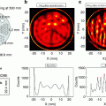
Fig. 5.1
Reduction of the artifacts present around the bladder in non-TOF reconstruction. Reprinted from [1] with permission of the Society of Nuclear Medicine
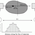
Current commercial TOF-PET systems partially address this issue: the TOF information reduces the noise propagation during the reconstruction process by localizing each event in a LOR segment (prelocalization) rather than spreading statistical noise along the full length of the LOR [2]. Campbell et al. [3] quantified the improvement provided by the TOF information in estimating the noise reduction factor f obtained for the reconstruction process as a function of the time resolution (TR) and of the diameter of the body imaged (Table 5.1).
Table 5.1
Noise reduction factor f obtained in function of the time resolution (TR) of the TOF-PET and of the diameter of the body (20 and 35 cm)
TR (ps) | PL (mm) | f | |
|---|---|---|---|
20 cm | 35 cm | ||
1,000 | 150 | 1.3 | 2.3 |
500 | 75 | 2.7 | 4.7 |
20 | 3 | 66.7 | 117.0 |
There is another aspect of the improvement rarely discussed that concerns an interesting benefit to improve the decay prelocalization: the modification of the noise properties in the reconstructed image. In planar acquisition the noise in the image follows a Poisson distribution and is spatially uncorrelated, i.e., the noise affecting a pixel depends only on the value of this pixel and its variance is equal to the square root of this value. In tomography, the activity in a reconstructed voxel is obtained from the measurement of the total activity on all the LORs traversing that voxel. Consequently, the noise does not longer follow a Poisson distribution and is furthermore spatially correlated, i.e., the noise affecting a voxel also depends on the values of the other voxels in the image. This explains why the planar images usually appeared more natural and more comfortable for the human vision. Lastly, this spatial correlation induces artifacts, especially in the neighborhood of highly active organs (Fig. 5.1). The prelocalization provided by TOF reduces this spatial correlation and the artifact generation. For an ultimate time resolution lower than 25 ps, TOF-PET will directly localize the annihilation in the correct 4-mm voxel without any reconstruction process. At that time, the noise in the tomographic image will follow the Poisson law and will be spatially uncorrelated, such as in planar image.
5.2 New Technology Developments in SPECT
5.2.1 More and More Solid: End of the PMT Age
The photomultiplier tube (PMT) was invented in 1934 by Harley Iams and Bernard Salzberg who joined together in the same vacuum housing the photoelectric effect discovered in 1887 by Heinrich Hertz (explained in 1905 by Albert Einstein) and the amplification tube invented in 1919 by Joseph Slepian (Fig. 5.2). The birth and the development of the nuclear medicine are so much linked to the PMT to pay tribute to these great scientists.
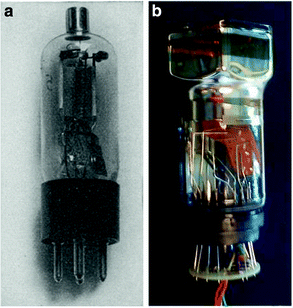

Fig. 5.2
(a) First PMT invented by Iams and Salzberg (reprinted from [4] with permission of IEEE). (b) Modern buttable PMT used in gamma camera
In 1947 the transistor, a solid-state version of the amplification tube, was invented by John Bardeen, William Shockley, and Walter Brattain at the Bell Company. Solid-state components have structural benefits versus vacuum glass tubes: they are insensitive to magnetic fields, they are more robust, they have a longer life, their performances do not change with age, they are more compact, and they don’t require a high voltage source. Although the transistor performances were still below those of the amplification tube, these structural benefits were already sufficient for Sony to introduce the first whole transistor radio in 1955.
The commercial success of an electronic component requires two distinct steps: (1) the invention and performance improvement of the component and (2) the development of an industrial process to reproducibly manufacture the component at an attractive cost. This second step is often the most expensive step. All electronic devices require signal amplification, and the amplification tube got a mass success with the worldwide spreading of the television in the beginning of the golden 1960s. This growing large market motivated major electronic device manufacturers, such as Bell, RCA, Sony, and Philips, to focus their efforts in improving the noise and speed performance of transistors. During the 1970s the performances of transistors dramatically overpassed those of the amplification tubes. Transistors replaced tubes in all the existing applications and opened new fields such as computer, high-frequency satellite communications.
In contrast, PMTs are used only in some scientific applications and rarely in a tile assembly. Although the photovoltaic property of the p-n junction had been observed in 1940 by Russell Ohl already 7 years before it was used in the transistor, comparatively less efforts were spent by the major manufacturers to develop a reproducible and commercially production process of four-side buttable solid-state components to replace the PMT. Nowadays 98 % of the nuclear medicine system is still based on the PMT scintillation counter invented in 1944 by Samuel Curran, and the development of solid-state replacement components is still mainly the job of “small” companies.
Two solid-state components emerged to replace the PMT: the avalanche photodiode (APD) (Fig. 5.3) and the Geiger-mode avalanche photodiode (G-APD) that can detect single photon just like a PMT with a very high gain and therefore is often called silicon photomultiplier (SiPM). At the same time, besides the pure replacement of the PMT, the cadmium zinc telluride (CZT) detector that replaces the crystal-PMT tandem was also developed. CZT can be seen as a kind of photodiode directly sensitive to γ-rays.
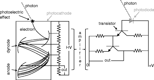

Fig. 5.3
Schematic diagram of the photomultiplier tube (left) and of its solid-state replacement (right). Photo sensitive areas are about π 302 mm2 and about 2 × 2 mm2 for the photomultiplier tube and for the photodiode, respectively. With avalanche photodiode, the major part of the gain is already provided by the avalanche process occurring inside the photodiode
As shown in Table 5.2, solid-state detectors are still expensive, and their performances begin to reach, but not to clearly overpass, those of the PMTs. The wide introduction of the solid-state components in nuclear medicine imaging will proceed in three phases similarly to the transistor story.
PMT | APD | SiPM | CZT | |
|---|---|---|---|---|
Gain | 10 7 | 103 | 10 6 | n.a. |
Noise | Low | Moderate | Low | Low |
Threshold (ph.e) | 1 | 10 | 1 | n.a. |
Timing resolution | 0.5 ns | 1 ns | 0.5 ns | 7 ns |
Energy resolution | 10 % | 13 % | 10 % | 4 % |
Cost | $ | $$ | $$$$ | $$$ |
MR compatible | No | Yes | Yes | Yes |
The first phase, equivalent to the introduction of the whole transistor radio in 1955, already started a few years ago. Although expensive, the structural properties of the solid-state detectors offer potential for new acquisition techniques. The compactness significantly reduces the size and the weight of the detector by decreasing the area of the shielding housing, thus resulting in a simplification of the gantry mechanic. In addition, contrary to the Anger camera that has a large dead area on the four edges of the crystal, all the CZT array surface is usable. The dead area of the detector is thus reduced to the housing thickness, i.e., less than 1 cm using tungsten as shielding material. These features allow static small CZT detectors to be set close together and focusing to a common target, as in the GE cardiac UFC [6]. Faster and more sophisticated motions can also be introduced, such as those used in the recently commercialized cardiac CZT D-SPECT camera (Spectrum Dynamics, Haifa, Israel) (Fig. 5.4). Lastly, the insensitivity to magnetic fields opens the development of simultaneous PET-MRI acquisition systems (as mentioned in Chap. 4).
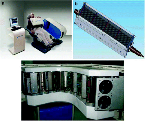

Fig. 5.4
Cardiac D-SPECT camera made of nine fast rotating compact column detectors (c) made of CZT detectors (b) scanning the heart region (a). (b) shows a column detector without its collimator; all the CZT pixels up to the housing edge are used. Reprinted from [6] with permission of Springer
The second phase, equivalent to the use of the transistor in the television, will start when the CZT cost will approach the crystal-PMT tandem cost. At this time, the better energy resolution provided by the CZT will on its own justify its use in all clinical SPECT systems: by reducing the scatter contribution, it will improve the image contrast, especially in heavy patient for whom the SPECT quality is the lowest.
The last phase, equivalent to the development of any new technology such as the computer, will occur when the performances of the solid-state detectors will overpass those of the PMTs and become sufficient for new acquisition concepts such as efficient Compton camera or positron emission locator. These concepts will be discussed in the following sections.
5.2.2 Lighter and Faster: The Compton Camera
Electronic collimation is the feature that, by avoiding the mechanical collimator, makes PET sensitivity and spatial resolution better than SPECT by a factor of about 100 and 3, respectively. Differently from the annihilation γ-rays produced by positron emitters, the direction of the multiples γ-rays emitted by the other isotopes is not strongly correlated. Thus, when a γ-ray is recorded by a collimated detector (typical efficiency ≈10−4), the probability that another γ-ray, originating from the same decay, has the right direction to be recorded by this detector, or another collimated detector, is almost zero (e.g., ≈10−8 to detect the two γ-rays emitted by 111In). As a result, only one γ-ray is recorded per decay, justifying the name “single-photon emission” for the method. An alternative way to obtain information about the incoming direction of a single photon, besides the use of a mechanical collimator to remove the photons of unwanted direction, is to measure the crossing point of the photons trajectory in at least two different planes.
Already in 1974 Todd et al. [7] proposed to use two detectors in series to perform an electronic collimation in a single-photon camera and to perform 3D acquisition such as in PET. The first detector is optimized to favor Compton scattering, while the second is a classical γ camera that measures both the crossing point of the trajectory and the residual energy of the recoil photon. Knowing the energy of the primary photon and measuring the energy of the scattered photon, it is possible to determine the scattering angle θ and therefore the cone surface where the source is located. However, after one-third of century of research, no compact functional Compton camera has yet been produced due to the lack of a suitable Compton detector. Such a detector has to be as large as possible and of high density in order to provide good efficiency and a high spatial resolution, it has to be made with material with low Z to favor the Compton scattering, and the electronic layers behind the detection volume area, if present, have to be fully transparent to the scattered photon to avoid additional Compton scatterings and thus supplementary changes in direction. This last condition has prevented the use of PMTs that up to recent years was the only affordable way to build large area efficient detectors.
Even using APD or CZT, the construction of such large Compton detector with hundreds of thousands detection elements, each with a volume less than 2 × 2 × 2 mm3, is difficult since each element requires high-resolution readout channels. The recent development of new application-specific integrated circuits (ASIC) partially addresses this issue [8]. Another way is to use double-sided skew-strip segmented planar silicon [9–12] or nitrogen-cooled germanium [13] detectors. Using these devices, the readout electronics is located on the edge of the detector area, outside the photon trajectories.
The Compton relation describing the photon energy conservation joined with the measure of the two crossing points of the trajectory in the two detector planes and of the residual energy of the recoil photon gives the equation of the cone in which the decay has occurred (Fig. 5.5). It is worth noting that even if a high improvement in sensitivity could be obtained, the situation is however not so favorable as that in PET, where the electronic collimation determines a single LOR or, more exactly, a thin cylinder due to limitation in spatial resolution. In Compton camera, the electronic collimation gives a cone surface that can have a large aperture angle θ (Fig. 5.5) and also with some thickness due to limitation in energy resolution.
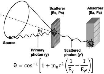

Fig. 5.5
Schematic rendering and principle of a Compton gamma camera. Reprinted from [9] with permission of Elsevier Ltd
5.2.3 The Recoil Electron-Tracking Compton Camera
Kabuki et al. [14, 15] proposed an elegant method to achieve the determination of a single LOR for a Compton camera, such as in PET. Beside the energy conservation, momentum is also conserved in elastic collisions. Linear momentum is a vector defined by the direction of the particle motion. Its module for matter is the particle mass times the velocity and, for a photon, as observed by Arthur Compton in 1922, is the energy divided by the speed of light, i.e., E/c. Due to the law of conservation of linear momentum, the trajectories of the incident photon, of the recoil photon, and of the recoil electron are coplanar. Using a micropixel high-pressure gas chamber, Kabuki et al. built a Compton camera that enabled to track also the recoil electron path (Fig. 5.6).
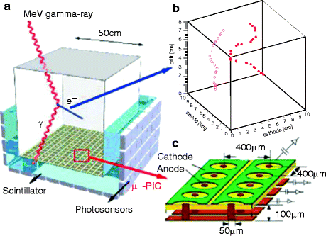

Fig. 5.6
Schematic rendering and principle of a recoil electron-tracking Compton gamma camera. (a) Gas detector. The scattered gamma-ray is detected using the scintillator-photosensor tandem, and the recoil electron is tracked by the μ-PIC detector. (b) Typical electron paths. (c) Expanded view of the μ-PIC detector. Reprinted from [14] with permission of Elsevier Ltd
With this device, the location of the decay is then restricted to the two lines defined by the intersection of the cone (deduced from the recoil photon analysis) with the plane defined by the trajectories of the scattered photon and of the recoil electron. Only one of these two lines satisfies the vectorial law of the momentum conservation, resulting in a single LOR. A first image of a thyroid phantom was obtained using this technique (Fig. 5.7, right). The low quality of the image does not prejudice the final quality that it will ultimately be possible to reach. For example, Fig. 5.7 (left) shows the first image of a thyroid obtained using a PMT-NaI detector that has been the state-of-the-art detection technique during 50 years.
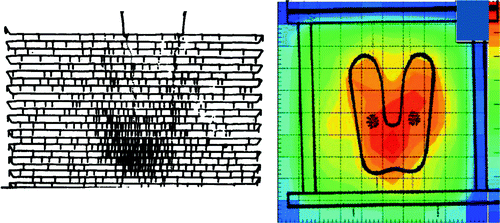

Fig. 5.7
Left: the first image of a patient thyroid obtained with a PMT-NaI detector by Benedict Cassen in 1950 (reprinted from [16] with permission of Elsevier Ltd). Right: the first image of a thyroid phantom filled with 131I obtained with the recoil electron-tracking Compton camera (Reprinted from [14] with permission of Elsevier Ltd)
Contrary to the Anger camera, a Compton camera has a wide energy dynamic, ranging from 100 to 3,000 keV. This opens the use of high-energy emitters such as 83Sr (33h), 198Tl(7h), 199Tl(7h), 204Bi(11h), 205Bi(360h), 95Tc (20h), and 96Tc(103h). The two technetium isotopes could be particularly interesting for assessing slow processes.
5.2.4 The SPECT Ultimate Goal: Multiple Coincidences Compton Camera
Using several Compton cameras positioned along a polygon setup around the patient, all the 360° directions are covered removing the need to rotate the camera. In addition, contrary to multi-head SPECT using mechanical collimators, the system can record all the γ-rays originating from a single decay.
In 1987, Liang et al. [17] pointed out that, using these Compton cameras in coincidence, the decay must have occurred on the intersection of several cones (Fig. 5.8). With isotopes emitting two γ-rays in cascade such as 111In or 67 Ga, the decay event will be located on 1 or 2 closed curve lines being the intersection of the two cones (Fig. 5.8a). Using isotope-emitting three γ-rays in cascade such as 130I or 94Tc, the intersection of the three cones will reduce to a finite number of points, in the most favorable case only 1 point (Fig. 5.8b). Of course, increasing the coincidence multiplicity decreases the system efficiency: keeping only triple coincidences events efficiency is expected to fall to that of conventional SPECT (≈10−4) [18]. However, each of such recorded events will be much more informative than in no-coincidence mode, and by only considering triple-coincidence intersections, reducing to 1 point will make the reconstruction process superfluous (the benefits of this feature have already been discussed in Sect. 5.1).
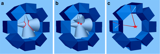

Fig. 5.8
Improved accurate position information can be obtained using an octagon of 8 Compton cameras working in coincidence. (a, b) conventional Compton camera with isotopes emitting at least two or at least three γ-rays, respectively. (c) Recoil electron-tracking Compton camera with isotope emitting at least two γ-rays (top and left detectors are shown open to illustrate the recoil photon and the recoil electron tracking)
Using several recoil electron-tracking Compton cameras like the one proposed by Kabuki, all the two γ-rays coincidences will directly provide the decay position (Fig. 5.8c). To this end, the coincidence triggering has to be performed using the first detector, i.e., the Compton camera that is a fast silicon detector. A recent prototype of such Compton camera working at atmospheric pressure showed a single-photon efficiency of 1.5 × 10⁻⁴ for energies above 150 keV and for a 10 × 10 × 10 cm3 detection volume [15], equivalent to an efficiency of about 0.4 % for 30 × 30 × 30 cm3 detection volume. Simulations have shown that at higher-pressure values, this detector volume could provide an efficiency of about 2 % [14]. Surrounding the patient by such detectors, such as in Fig. 5.8, the single-photon efficiency should be around 10 %. When working in two γ-rays coincidences, the sensitivity should be similar to that of 3D PET, i.e., ≈1 %, but again without the need of using a reconstruction process. Substances labeled with 94Tc(4.9h), 95Tc(20h), 96Tc(103h), 111In(67h), 198Tl(7h), 199Tl(7h), and 67Ga(78h) will be usable and, as a consequence, also most of the radiopharmaceuticals developed for SPECT. For isotopes emitting n γ-rays in cascade per decay, the efficiency of detecting at least two photons in coincidences is n × eff × (n–1) × eff, where eff is the detector efficiency. Thus, for 96Tc that emits at least three γ-rays of energy around 800 keV, the efficiency will thus further be improved by a factor 3 versus a radionuclide-emitting two photons. Obviously, such sensitivity estimations are based on preliminary simulations and have still to be confirmed by real prototypes.
5.3 New Technology Developments in PET
5.3.1 The PET Ultimate Goal: 25 ps TOF-PET
The concept of positron imaging was introduced by Sweet and Brownell in 1950 and is anterior to the development of the γ camera by Anger starting in 1952 [19]. A first positron image of a patient was already obtained in 1953 using a rectilinear scanner made of two opposing detectors [19]. However, the first true positron camera was constructed in the late 1960s and consisted of two Anger γ cameras. The hardware collimator is the major component limiting the sensitivity and spatial resolution of single-photon imaging system, and its replacement by the electronic collimation in positron imaging resulted in a significant improvement.
The real precursor of modern emission tomography was Kuhl and Edward’s scanner [20] in 1964, which used two opposing detectors making a single sweep at angular orientations around 360°. However, the system was purely analogical and provided just a back projection, i.e., without ramp filtering, of the acquired projection lines. A major improvement was the introduction in the beginning of the 1970s of the computers that allowed inverting the Radon transform to reconstruct the 3D activity distribution that is supposed to have generated the acquired planar views.
During time, with the improvement of the computer speed, more and more sophisticated algorithms were introduced, which better modeled the acquisition process and the Poisson nature of the nuclear decays. That resulted in a continuous improvement of SPECT and PET quality. Recently, with the measurement of the time of flight (TOF) difference between the two 511 keV γ-rays, PET is on the way to get free of the computer by directly measuring the annihilation position.
Since the introduction of PET with a filtered back-projection algorithm by Ter-Pogossian et al. in 1975 [21], the time resolution improvement of the system has been a major concern to the end of getting rid of the random coincidences, which are proportional to the coincidence time window. One should consider that this random coincidence contamination in conventional PET cannot indefinitely be reduced due to the necessity of having a coincidence time window larger than the time needed for the γ-ray to travel the field of view (FOV), i.e., 2 ns for a 60 cm FOV.
The use of TOF information to prelocalize the positron annihilation was already explored in the early 1980s. The requirement of a sub-nanosecond time resolution in order to improve the image reconstruction disqualified the BGO, and many experiments were carried out on a two-arm detector setup using CsF and BaF2 crystals (Fig. 5.9). An excellent time resolution of 106 ps was already obtained in 1989 [22]. TOF-PET using CsF and BaF2 crystal was built, achieving a good system time resolution of about 550 ps [23, 24]. However, the low light outputs and the low stopping power of these crystals hamper the spatial resolution and the sensitivity. Timing stability of these systems was also challenging, and their overall performances did not overpass those of conventional BGO systems. Only at the end of the 1990s, the development of somewhat less fast crystals, but with a higher light yield, raised again interest in TOF-PET systems.
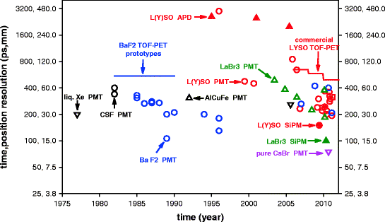

Fig. 5.9


Scientific publications reporting coincidence time resolutions in experimental two-arm detector setup. Empty and filled symbols correspond to PMTs and photodiodes, respectively. Difference in time resolution for same crystal-photodetector tandem results from differences in crystal size, photodetector model, doping level, and electronic design for signal processing. 25 ps correspond to an annihilation localization accuracy of 3.8 mm avoiding the need of a reconstruction process. Note the increasing number of publications these last 5 years
Stay updated, free articles. Join our Telegram channel

Full access? Get Clinical Tree


