PET Physics and PET Instrumentation
Timothy G. Turkington
Positron emission tomography (PET) quantitatively measures the biodistribution of positron emitting radiotracers in vivo. Positrons emitted from positron-emitting radioisotopes radiotracers, which travel a short distance in tissue, subsequently annihilate and form two 511 keV photons that may be detected by a ring of detectors. Images are produced from the detection of such coincidence counts in a spatially relevant manner. This chapter discusses the basics of positron physics, coincidence detection, PET scanner design, phenomena that degrade PET images, and the union of PET and computed tomography (CT). More extensive information on PET instrumentation can be found in Wernick and Aarsvold (1).
Positron Physics
Positron Decay
A nuclide is a specific combination of protons and neutrons in a nucleus. The number of protons (which is called the atomic number, or Z) dictates which chemical element the nuclide is, since it gives the total charge on the nucleus, which in turn dictates the nature of the electron structure of the atom. The number of neutrons plus the number of protons is the mass number. Only certain combinations of neutrons and protons lead to stable nuclides. Those that are not stable, referred to as radionuclides, decay, releasing energy in the form of radiation. The most common way to designate a particular nuclide is to specify the element, which in turn specifies the number of protons and the mass number, which specifies the sum of protons and neutrons. Isotopes are defined as multiple nuclides that share the same atomic number, but it is common in nuclear medicine and physics to use the term isotope interchangeably with nuclide.
Radionuclides that are not stable due to an abundance of protons can decay via the emission of a positron:
where X is the original nuclide, with Z protons, N neutrons, and mass number A, Y is the new nuclide, with one more neutron, one fewer proton, and the same mass number, e+ symbolizes the positron and ν is a neutrino, which has very little mass and interacts extremely weakly with matter. Energy is released in the decay in the form of kinetic energy of the released particles. The positron is the antiparticle counterpart to the electron, and it is opposite to the electron in all ways that there is an opposite (such as charge) and the same in all ways that there is not a known opposite (such as mass).
The kinetic energy of the annihilation is shared between the electron and the neutrino. Unlike gamma decays, in which the emission is always at a particular energy for a particular decay scheme, the positron and neutrino share the energy in variable proportions, so that the positron can have any amount of energy from zero up to the maximum available in the decay.
In addition to the decay energy that differs from one positron emitting radionuclide to the next, the other important variable is half-life. Radioactive decay is a random process, and the number of atoms in a sample that will decay over some time interval is proportional to the number in the sample. This characteristic makes the decay process an exponential one, that is, the number of atoms in a sample that have not decayed is an exponentially decreasing function of time and a constant specific to the radionuclide. It is typical to represent the decay as a half-life, that being the time in which half of a sample will decay. Several PET radionuclides are listed in Table 3.1.
Of the radionuclides listed, the first four are cyclotron- produced, and rubidium-82 [82Rb] comes from a generator that can be purchased. Of the currently commonly used cyclotron-produced radionuclides, only fluorine-18 [18F] has a long enough half-life to be transported; the first three must be produced on site and therefore require an on-site accelerator. Iodine-124 [124I] and certain radioisotopes of copper also have sufficiently long half-lives to be transported, but are not in widespread use.
Positron Annihilation
When a positron is created in tissue, it travels a short distance, undergoing the same interactions as an electron (β particle) would, giving up energy to ionize and excite nearby atoms. When the
positron has lost almost all its energy, it interacts with a nearby electron, resulting in the creation of two photons (Fig. 3.1) This annihilation reaction obeys conservation of energy and conservation of momentum, which dictate that the two photons will leave the annihilation site in opposite directions, each with an energy of 511 keV (the energy corresponding to the mass of the electron).
positron has lost almost all its energy, it interacts with a nearby electron, resulting in the creation of two photons (Fig. 3.1) This annihilation reaction obeys conservation of energy and conservation of momentum, which dictate that the two photons will leave the annihilation site in opposite directions, each with an energy of 511 keV (the energy corresponding to the mass of the electron).
Table 3.1 Radionuclides Used for PET | ||||||||||||
|---|---|---|---|---|---|---|---|---|---|---|---|---|
|
Coincidence Detection
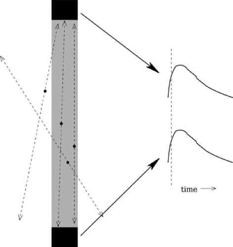
The generation of two back-to-back photons of known energy provides much more information than does the generation of a single photon. Fig. 3.2 depicts the generation of annihilation photon pairs at multiple locations relative to a pair of radiation detectors. If the annihilation occurs within the column that connects the detectors, there is a possibility (depending on the direction of the photons) that both photons will be detected. Likewise, if an annihilation leads to the detection of both photons, it can only have happened if the annihilation was in the column connecting the detectors. Also depicted in Fig. 3.2, are two pulses representing the electronic pulses that would come simultaneously from two detectors if hit by photons from the same annihilation. (For conventional PET, the difference in arrival time of the two photons to their respective detectors, due to different path lengths, is considered small enough to be negligible.)
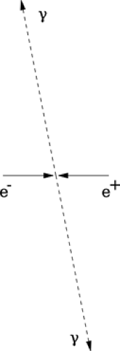 Figure 3.1. Positron annihilation. A positron and electron join together, resulting in the back-to-back emission of two 511 keV photons. |
Basic PET Scanner
In a basic PET scanner, a section of the patient is surrounded by a ring of detectors, as depicted in Fig. 3.3. Any photon pairs leaving the body in the plane of the detector ring can be detected, and the particular detector pair subsequently registering the detection of 511 keV photons defines a column in which the annihilation must have occurred. Fig. 3.3 depicts one particular photon pair’s trajectory and the corresponding detector pair and column. This is but one of a whole continuum of possible emission angles that would be detected by the ring. Unfortunately, far more photon pairs will leave the body undetected because they are not in the plane of the detector ring. In any case, even a small amount of radioactivity in a small region of the body will emit enough positrons, and therefore photon pairs, that radiation will be detected along many of the columns (also called lines of response [LORs]). For example, a cubic centimeter of tumor tissue may contain 1 μCi or more of radioactivity, which corresponds to 37,000 decays per second.
During a PET scan, the system is counting the number of times each detector pair is hit in coincidence, referred to as a coincidence event, so the raw data from a PET scan are simply the list of counts obtained along each line of response.
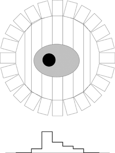
Fig. 3.4 depicts a simple body cross section with a uniform distribution of radioactivity plus a lesion with more concentrated radioactivity. Also depicted are the vertical lines of response. The
profile at the bottom represents the relative number of counts that might be expected along the vertical lines of response, with more counts coming from thicker sections of the body and even more coming from the lesion region. The distribution of counts along one direction is a projection of the distribution of radioactivity. Although only one projection angle is depicted, the PET scanner is simultaneously measuring all possible projection angles. This is in contrast to SPECT (single-photon emission computed tomography) acquisition, in which the gamma camera obtains only one projection angle at a time and orbits around the body to obtain the full set of projection angles needed to produce cross-sectional slices.
profile at the bottom represents the relative number of counts that might be expected along the vertical lines of response, with more counts coming from thicker sections of the body and even more coming from the lesion region. The distribution of counts along one direction is a projection of the distribution of radioactivity. Although only one projection angle is depicted, the PET scanner is simultaneously measuring all possible projection angles. This is in contrast to SPECT (single-photon emission computed tomography) acquisition, in which the gamma camera obtains only one projection angle at a time and orbits around the body to obtain the full set of projection angles needed to produce cross-sectional slices.
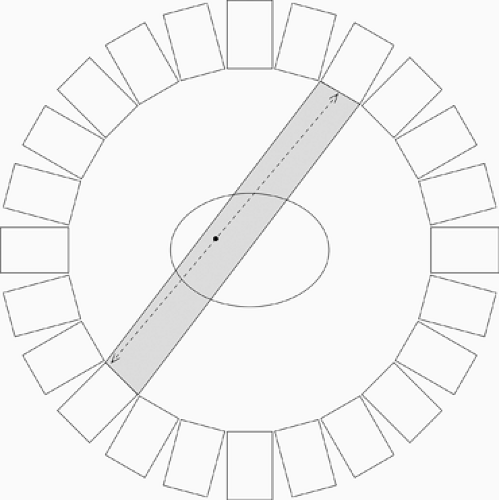 Figure 3.3. Simple PET ring. When any two detectors in the ring are hit simultaneously it indicates that an annihilation occurred within the column connecting the detectors. |
Scanner Design
Multiple factors of image quality have driven the design of PET scanners. A fundamental requirement is to have as much sensitivity for detecting true events as possible. Spatial resolution should also be good. Limiting background counts is another goal that will be discussed later.
Spatial resolution in PET has two fundamental limits. The first is that the positron goes a short distance in tissue before it annihilates. It is the location of the decay that is of interest, but the scanner sees the annihilation site. There is, therefore, a small blurring due to the average positron range. Fortunately, this range is small (<1 mm for [18F] positrons). An additional limit is that the photons are not actually emitted at exactly 180 degrees from one another due to the momentum of the positron. This factor has a larger effect for larger diameter detector rings, but is still relatively small.
An additional factor that can be controlled is the size of the individual radiation detectors. With smaller detectors, each coincidence event can be localized to a smaller column, leading to better spatial resolution. All current commercial human PET systems use detectors composed of scintillation crystals and photomultiplier tubes (PMTs). The 511 keV photons interact in the crystal, producing light. Some of the light is then collected in the PMT and converted into an electronic pulse.
Early PET systems used detectors that coupled a single crystal to a single PMT. This led to count and resolution limitations. The desire for smaller detectors lead to the block design (2). In this design, a small array (from 6 × 6 up to 13 × 13) of crystals, or a block of crystal with an array cut into one end, is coupled either to four PMTs or to a single square PMT with four separate quadrants on its face. This unit functions similarly to a small gamma camera, with the sum of all PMT signals representing the energy of an impinging photon, and with the differences in signals being used to determine which of the crystals was hit. This design allows for more than 10,000 very small crystals (currently ∼4 × 4 mm2 to ∼6 × 6 mm2) without the corresponding size and number requirements for the PMTs, which would be cost prohibitive. Systems that use block detectors currently use three or four rings of these blocks, resulting in 18 to 52 rings of individual crystals. A block-based PET ring is shown in Fig. 3.5.
Although all PET images reflect the three-dimensional (3D) location of radioactivity throughout the body, all PET scanners operate in one of two modes: two-dimensional (2D) or 3D. Fig. 3.6 illustrates the two modes. In the simplest 2D PET operation, only those pairs in which both photons are detected in the same ring are recorded, and data are stored and reconstructed independently, plane by plane. Additional planes are formed by photon pairs that are detected in adjacent rings. Higher sensitivity is achieved in 2D PET by including additional photon trajectories as shown, but all are recorded as if they came from the central plane.
 Figure 3.5. Block-based ring. Detector units (blocks) in many PET systems comprise a small number of photomultipliers reading an array of many small scintillator crystals. Blocks in this ring have a dimension of six crystals in the visible (tangential) direction.
Stay updated, free articles. Join our Telegram channel
Full access? Get Clinical Tree
 Get Clinical Tree app for offline access

|
