Physics and Image Artifacts
 UNDERSTANDING SOUND AND ULTRASOUND
 PRINCIPLES OF ULTRASOUND PHYSICS
 MODES
MODES
 TWO-DIMENSIONAL IMAGING
 IMAGE ARTIFACTS
 MAINTENANCE AND QUALITY ASSURANCE
 BIOLOGICAL EFFECTS
Diagnostic ultrasound has experienced tremendous technological advances. Over the past 50 years, ultrasound has evolved from a single specialty tool with large bulky machines to a technology that is highly compact and portable. The development of smaller, less expensive ultrasound systems has increased the number of medical specialties utilizing ultrasound. Many are discovering the benefits of “point-of-care” diagnostic ultrasound. Medical students, nurses, mid-level providers, and physicians have embraced ultrasound as a tool to facilitate patient evaluation and improve outcomes of invasive procedures. The operator must have a basic understanding of the physical principles of ultrasound. It is these principles upon which ultrasound bases its ability to be an effective tool in medical imaging.
 UNDERSTANDING SOUND AND ULTRASOUND
The simplest way to describe ultrasound is in the pulse-echo principle. Sonar can be used as an example of the forerunner of diagnostic ultrasound. A submarine that possesses sonar capability can precisely control when an acoustic pulse is generated. It assumes a relative propagation speed as it travels through a specific medium (water). The amount of elapsed time required for the “echo” to return subsequent to striking an object allows the relative distance to be calculated to the target of interest.
Diagnostic ultrasound uses the same concept of the pulse-echo principle. Electric current is passed through crystals in the transducer and generates a sound wave. This piezoelectric effect generates a constant pulse of high-frequency, longitudinal, mechanical sound waves that can be measured and used in calculations. This pulse travels at a relatively constant speed until it encounters a reflective surface, which causes a fraction of the sound to reflect back toward the transducer crystal. When the returning sound wave strikes the crystal, it generates an electrical impulse that is processed into a diagnostic image. Based on the assumption that sound travels at the same speed through all tissues (1540 m/s), a computer measures the round-trip time and intensity of each returning “echo.” The amount of time required for the returning echo determines its relative distance from the transducer while the returning intensity is proportional to the grayscale assignment of the pixel. Each returning echo is presented as a pixel (dot) of information on the display device.
Sound waves are actually a series of repeating mechanical pressure waves that propagate through a medium (Figure 3-1). These pressure waves are measured in hertz (cycles/second). Typically, audible sound ranges between 16,000 and 20,000 Hz. Ultrasound is technically defined as a “sound” having a frequency in excess of 20,000 Hz. In medicine, ultrasound used for diagnostic purposes incorporates frequencies that generally range between 2 and 15 million cycles/second, or 2 and 15 MHz, well above the range of human hearing.
Figure 3-1. Time versus pressure graph of a sound wave. Amplitude: peak pressure of a wave. Period: time required to complete a single cycle. (Courtesy of SonoSite)
 PRINCIPLES OF ULTRASOUND PHYSICS
AMPLITUDE
Amplitude is the peak pressure of the wave (height). This may be simply interpreted as the loudness of the wave. Amplitude correlates with the intensity of the returning echo. A loud sound has large amplitude while a soft sound has small amplitude (Figure 3-1).
PERIOD
Period is the time required to complete a single cycle.
FREQUENCY
Frequency is the number of times per second the wave is repeated. The range of frequencies typically discussed here is between 2 and 15 MHz.
SPATIAL PULSE LENGTH
A diagnostic ultrasound transducer generates an image by sending and receiving ultrasound waves. It receives the returning, or reflected, ultrasound waves; the generation of ultrasound waves usually occurs less than 1% of the time. The period where it generates ultrasound waves is termed a pulse. Spatial pulse length is the distance or length of each pulse. Spatial pulse length is determined by the frequency and pulse duration.
Transducer technology is based on the piezoelectric effect. Piezoelectric is defined as “pressure-electricity” and refers to materials that have a dual function of converting electric energy into mechanical energy (pressure) and conversely mechanical energy (returning echo) into electrical energy. While quartz is a naturally occurring crystal, the crystal elements in modern transducers are synthetic. The arrangement and the number of crystals within a transducer vary depending on the manufacturer, transducer design, and its intended application.
Transducer frequency has a direct effect on image quality and resolution. In general, high frequencies result in higher resolution and enhanced image quality. While resolution may increase, tissue penetration will decrease. Lower frequencies result in lower resolution, but have better tissue penetration.
Resolution is the result of the spatial pulse length as well. Higher frequency provides more reference points or pixels over a similar spatial distance and thus produces higher resolution by displaying smaller tissue segments. However, the trade-off is that the higher frequency will not travel as far or penetrate deep tissue.
BANDWIDTH
Historically, ultrasound transducers emitted only one frequency. As ultrasound equipment became more sophisticated, each transducer could generate multiple different frequencies, but could only send one frequency at a time. Modern ultrasound transducers emit a “center” frequency during the transmit portion of the cycle. A range of frequencies exists on either side of the center frequency and is known as the bandwidth (Figure 3-2). The resulting frequency is actually an average of the frequencies in the bandwidth.
Figure 3-2. Broad bandwidth or multifrequency selectable transducers.
Many ultrasound systems make use of these bandwidth frequencies during the received portion of the cycle and thus incorporate broadband transducers. Technology may allow the operator to select one of multiple “center” frequencies available from a single transducer. This selection allows the operator to easily maximize the transmit frequency of the transducer that offers the best resolution or best penetration for the area of interest. Regardless of which type of transducer technology is utilized, the highest frequency should be used that will penetrate the area of interest and that offers the best resolution.
Image resolution is based on many transducer factors including the spatial pulse length of the wave. The spatial pulse length is dependent on specific transducer characteristics set by the manufacturer. This may explain why simply increasing the transmit frequency of a transducer may not consistently result in improved resolution or improved image quality.
VELOCITY
Velocity of sound is defined as the speed of the wave. The velocity of sound is dependent on the material through which the wave is traveling. Velocity is independent of frequency. Since the speed of ultrasound through a given medium is constant, the closer the molecules are in position to one another, the better the propagation. Therefore, sound travels faster in bone than in human soft tissue. When molecules become less dense (gases), the velocity of the sound slows even further or may not propagate at all as is the case with a vacuum.
WAVELENGTH
Wavelength (propagation speed/frequency) is the distance the wave travels in a single cycle.
ATTENUATION
The attenuation of sound begins the instant the pulse is generated within the transducer and it continues throughout its round-trip path until the sound pulse returns to the transducer to be recorded as an “echo.” There are several factors that contribute to attenuation. These factors include the wavelength of the emitted sound, the medium through which the sound is traveling, and the number of interfaces it encounters.
The type and density of tissue combined with its degree of homogeneity or heterogeneity contribute to the rate of attenuation. Tissue of the same type and density facilitates the transmission of sound. Ultrasound travels best, with the least attenuation, through homogeneous fluid-filled structures. This is why transabdominal ultrasound of the uterus and ovaries is facilitated by a distended urinary bladder. The fluid inside the bladder provides an acoustic window for the sound wave and allows an efficient use of the transmitted sound to visualize the posterior anatomy.
Reflection is a form of attenuation. It is the redirection of part of the sound wave back to its source. Reflection is the foundation upon which ultrasound scanning is based. The ultrasound beam should evaluate the anatomy of interest at 90 degrees to maximize the reflection and visualize the anatomical structures. Manipulating the transducer so the area of interest is positioned directly under the transducer in the center of the display offers improved visualization and the ability to better appreciate the surrounding anatomical structures.
Refraction is the redirection of part of the sound wave as it crosses a boundary of mediums possessing different propagation speeds. This condition worsens with non-perpendicular incidence (Figure 3-3).
Figure 3-3. Reflection and refraction.
Scattering occurs when the ultrasound beam encounters an interface that is smaller than the sound beam or irregular in shape. The term Rayleigh scattering is specific to red blood cells (RBC) (<5 microns) that are not normally seen unless they are clustered together making a larger surface area. This may occur when blood movement slows during stasis, early clot formation, or asystole. Spontaneous contrast is another term used to describe this phenomenon, which is best noted during real-time B-mode imaging
Absorption occurs when the energy of the sound wave is contained within the tissue. When the acoustic energy is converted into thermal energy, it dissipates as heat within the tissue. This forms the foundation for therapeutic ultrasound. For instance, physiatrists use therapeutic ultrasound to help patients recover from injuries by using an output power significantly greater than that of diagnostic ultrasound.
INTERFACES
When sound crosses a boundary of tissues having different acoustic impedance, an interface is said to occur. In emergency ultrasound, a classic interface is Morison’s pouch, where the liver abuts the hyperechoic renal fascia. This interface becomes more pronounced when anechoic fluid is seen in Morison’s pouch.
ACOUSTIC IMPEDANCE
Acoustic impedance refers to the resistance of the tissue to molecular movement. Acoustic impedance is directly related to tissue density. Blood, urine, fat, and muscle all have enough difference in acoustic impedance to generate a reflection when the ultrasound wave passes from one tissue to the next. Greater density difference between tissues produces greater or stronger reflection. The intensity of the reflection (how loud the echo is) is determined by how much of a difference in impedance exists between the tissues in contact. A small density difference (acoustic impedance) results in a small echo being generated. A large difference in density results in a large echo generated with much of the energy lost to reflection. Therefore, little energy remains available to continue for visualization of deeper structures. This explains why diagnostic ultrasound cannot “see” through bowel gas or bone, as there is too large a difference in acoustic impedance between these types of interfaces and soft tissue. This phenomenon is referred to as “acoustic mismatch” and will be covered further in the section on artifacts.
IMAGE RESOLUTION
Resolution refers to the quality of the image produced by the machine. It is the ability to differentiate the details of anatomical structures. While there are several factors that contribute to the overall image quality, we will limit our discussion to axial, lateral, temporal, and contrast resolution.
AXIAL RESOLUTION
Axial resolution is the ability to differentiate two closely spaced structures that lie in a plane parallel to the direction of sound wave propagation; that is, objects above one another on the viewing screen.
There are several factors that contribute to the quality of the axial resolution; however, the rate-limiting step under control by the operator is the ultrasound beam and transducer frequency. In general, higher transducer frequency produces better axial resolution and resultant image quality (Figure 3-4).
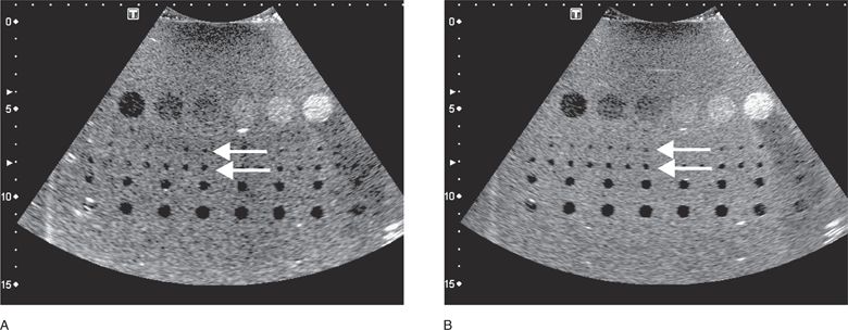
Figure 3-4. Axial resolution is improved by increasing the transducer frequency as the illustration demonstrates. Note how grainy and pixilated the lower frequency (1.9 MHz) image (A) is compared with the smoother characteristics of the higher resolution (5.0 MHz) image (B). Also, note the better visualization of the entire row of small cysts (top arrow) and the next row of slightly larger cysts (bottom arrow), along the “axis” of the transmitted beam. Both images were obtained using a multipurpose phantom. (Courtesy Model 539 Multipurpose, ATS Laboratories, Inc.)
Related posts:
Stay updated, free articles. Join our Telegram channel

Full access? Get Clinical Tree


