The radiologist serves as an indispensable consultant for those patients with wrist pain, by determining the causes of the pain and severity of the injury, helping to determine treatment options, and providing preoperative guidance for surgery, if planned. This article reviews normal anatomic variants and potential danger areas encountered by the radiologist when interpreting magnetic resonance imaging of the wrist.
Wrist imaging
The multiplanar capability coupled with excellent tissue contrast makes magnetic resonance (MR) imaging the ideal imaging modality to evaluate for myotendinous, ligamentous, and bone pathology in any joint. MR imaging of the hand and wrist has lagged behind that for other joints, in part because of the difficulty in accurately evaluating the diminutive anatomic structures. Technology such as improved coils, 3-T imaging, and short-bore open systems built to comfortably image the upper extremity have proved to increase the utility of MR imaging of the wrist. This article reviews fundamental pearls and pitfalls with corresponding images from 1.5-T systems that the practicing radiologist must be mindful of to provide clinically relevant information to the ordering doctor.
Wrist alignment
The normal anatomic relationships of the carpus have been validated over decades with standardized reproducible positioning for posteroanterior (PA) and lateral radiographs. For example, the standard radiographic PA view of the wrist is obtained with the wrist flat on the x-ray table, the shoulder abducted 90°, and the elbow flexed 90°. Once obtained, there are criteria that the radiologist can use to verify the images are satisfactory, which on the lateral view is based on the location of the extensor carpi ulnaris groove and on the PA radiograph is based on the location of the pisiform with respect to the palmar surface of the capitate and scaphoid. These anatomic relationships are important because poorly positioned radiographs may simulate pathology, such as carpal instability.
By contrast, positioning for MR imaging is variable. The wrist may be imaged at one’s side for those few patients who fit the bore of the magnet in this position. This position is comfortable, but the wrist is out of the isocenter of the magnet, which in turn decreases signal to noise and makes fat suppression more difficult. Alternatively, the superman position (prone position with arm extended) is commonly used for those who are able to tolerate the position. The benefit here is that the wrist is more in the center of the magnet bore, but the position is less comfortable for elderly patients and those with breathing difficulties. Regardless of position, the degree of pronation and supination, ulnar and radial deviation, and grip varies somewhat from patient to patient. As with poorly positioned radiographs, there is the possibility of misinterpreting pathology due to wrist positioning rather than a true pathologic process.
Static carpal instability may be diagnosed with radiographs based on classic anatomic relationships. Two examples of this are volar intercalated segmental instability (VISI) and dorsal intercalated segmental instability (DISI). Patients with DISI demonstrate dorsal tilting of the lunate and those with VISI demonstrate volar tilting of the lunate. The diagnosis is confirmed by measuring the scapholunate (SL) and capitolunate (CL) angles obtained from the true lateral radiograph ( Fig. 1 ).

DISI is diagnosed with a CL angle greater than SL angle of more than 80°. An SL greater than 60° but less than 80° is suspicious for DISI. VISI is diagnosed by demonstrating a CL angle less than −30° and SL angle less than 30°.
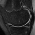
A “pseudo DISI configuration” is commonly seen on sagittal MR images, particularly when imaging in the “superman” position ( Fig. 2 ). This image may be the result of different mechanical load on the wrist in this position compared with that of the lateral radiograph. To avoid this pitfall, radiographic correlation is recommended before making the diagnosis of DISI or VISI on MR imaging. This correlation is particularly important in the absence of an SL and lunotriquetral (LT) ligament tear, which would support the diagnosis of DISI and VISI, respectively.

On standard PA radiographs, the articular surfaces of the ulna and radius are at the same level, termed neutral ulnar variance. With negative ulnar variance the radius projects more distal to the ulna, and with positive ulnar variance the radius projects proximal to the ulna ( Fig. 3 ). However, it is important to consider that wrist position and grip are significant determinants of ulnar variance. For example, ulnar positive variance increases with pronation and increased grip, and vice versa Thus, given the variability of wrist positioning on MR imaging, subtle isolated ulnar variance should not be diagnosed without first correlating with radiographs. Furthermore, in the presence of classic findings, the apparent lack of ulnar variance should not deter one from diagnosing ulnar impaction in the absence of ulnar positive variance, or Kienbock disease in the absence of negative ulnar variance.

Wrist alignment
The normal anatomic relationships of the carpus have been validated over decades with standardized reproducible positioning for posteroanterior (PA) and lateral radiographs. For example, the standard radiographic PA view of the wrist is obtained with the wrist flat on the x-ray table, the shoulder abducted 90°, and the elbow flexed 90°. Once obtained, there are criteria that the radiologist can use to verify the images are satisfactory, which on the lateral view is based on the location of the extensor carpi ulnaris groove and on the PA radiograph is based on the location of the pisiform with respect to the palmar surface of the capitate and scaphoid. These anatomic relationships are important because poorly positioned radiographs may simulate pathology, such as carpal instability.
By contrast, positioning for MR imaging is variable. The wrist may be imaged at one’s side for those few patients who fit the bore of the magnet in this position. This position is comfortable, but the wrist is out of the isocenter of the magnet, which in turn decreases signal to noise and makes fat suppression more difficult. Alternatively, the superman position (prone position with arm extended) is commonly used for those who are able to tolerate the position. The benefit here is that the wrist is more in the center of the magnet bore, but the position is less comfortable for elderly patients and those with breathing difficulties. Regardless of position, the degree of pronation and supination, ulnar and radial deviation, and grip varies somewhat from patient to patient. As with poorly positioned radiographs, there is the possibility of misinterpreting pathology due to wrist positioning rather than a true pathologic process.
Static carpal instability may be diagnosed with radiographs based on classic anatomic relationships. Two examples of this are volar intercalated segmental instability (VISI) and dorsal intercalated segmental instability (DISI). Patients with DISI demonstrate dorsal tilting of the lunate and those with VISI demonstrate volar tilting of the lunate. The diagnosis is confirmed by measuring the scapholunate (SL) and capitolunate (CL) angles obtained from the true lateral radiograph ( Fig. 1 ).

DISI is diagnosed with a CL angle greater than SL angle of more than 80°. An SL greater than 60° but less than 80° is suspicious for DISI. VISI is diagnosed by demonstrating a CL angle less than −30° and SL angle less than 30°.
A “pseudo DISI configuration” is commonly seen on sagittal MR images, particularly when imaging in the “superman” position ( Fig. 2 ). This image may be the result of different mechanical load on the wrist in this position compared with that of the lateral radiograph. To avoid this pitfall, radiographic correlation is recommended before making the diagnosis of DISI or VISI on MR imaging. This correlation is particularly important in the absence of an SL and lunotriquetral (LT) ligament tear, which would support the diagnosis of DISI and VISI, respectively.
On standard PA radiographs, the articular surfaces of the ulna and radius are at the same level, termed neutral ulnar variance. With negative ulnar variance the radius projects more distal to the ulna, and with positive ulnar variance the radius projects proximal to the ulna ( Fig. 3 ). However, it is important to consider that wrist position and grip are significant determinants of ulnar variance. For example, ulnar positive variance increases with pronation and increased grip, and vice versa Thus, given the variability of wrist positioning on MR imaging, subtle isolated ulnar variance should not be diagnosed without first correlating with radiographs. Furthermore, in the presence of classic findings, the apparent lack of ulnar variance should not deter one from diagnosing ulnar impaction in the absence of ulnar positive variance, or Kienbock disease in the absence of negative ulnar variance.
Wrist bone
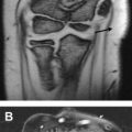
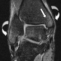
Ulnar impaction syndrome (also known as ulnar abutment) is secondary to abnormal loading of the wrist, resulting in progressive pain from impaction of the ulnar head against the lunate and triquetrum across a thinned or torn triangular fibrocartilage (TFC). Ulnar positive variance is classically present, but not always. The constellation of MR imaging findings seen with ulnar impaction include: central TFC thinning or tear, progressive cartilage loss, signal alteration in the ulnar head and adjacent ulnar aspect of the lunate and/or triquetrum, and LT ligament tear ( Figs. 4 and 5 ). These findings typically follow the aforementioned progression, closely reflecting Palmer’s classification system of degenerative TFC tears. Depending on the stage of the disease, the bony signal alteration may be that of fluid (low T1 and high T2 signal) or sclerosis (low T1 and low T2 signal). It is important that findings suggesting ulnar impaction syndrome be noted, in addition to diagnosing the central TFC tear, as treatment is not simple arthroscopic debridement as with symptomatic central TFC tear. The accompanying force imbalance at the ulnar head must be addressed (ulnar positive variance), which often requires resection of the distal ulna.
Additional conditions, such as Kienbock disease and carpal cysts, may mimic ulnar impaction on MR imaging. Incidental carpal cysts are frequent throughout the carpus. These cysts often form along ligamentous attachments, and therefore centrally located carpal bones like the lunate and capitate are frequently affected. The cysts may appear as small peripheral erosions at the ligament attachment, or may tunnel into the center of the bone ( Fig. 6 ). When signal changes are present in the lunate, distinction must be made between ulnar impaction syndrome, lunate cysts ( Fig. 7 ), and Kienbock disease. Both conditions are distinguished from ulnar impaction based on the location of the signal alteration in the lunate, which in ulnar impaction is limited to its ulnar side. Furthermore, with Kienbock disease the signal changes are typically more confluent ( Fig. 8 ), and may be accompanied by lunate collapse ( Fig. 9 ).
Distinction must be made between ulnar impaction and other similarly termed but separate syndromes that are also known to cause ulnar-sided wrist pain. Ulnar impingement is a condition whereby a short distal ulna impinges on the distal radius at the sigmoid notch, resulting in a painful and disabling pseudoarthrosis. Ulnar styloid impaction is similar, but the bony impaction is between the ulnar styloid and triquetrum, which is thought to be caused by morphologic changes in the ulnar styloid or nonunion of prior ulnar styloid fracture.
Large carpal cysts were demonstrated previously, but they vary in size and may be isolated or numerous ( Fig. 10 ). On MR imaging, both nutrient vessels and carpal cysts have been shown to mimic the early erosions of rheumatoid arthritis (RA), which may all develop in similar locations and commonly are present along ligament attachments. The distinction is not difficult in the later stages of RA, because the erosions are by then numerous and characteristic in location ( Fig. 11 ). However, it is preferable to make the diagnosis of RA early in the disease process to implement treatment as early as possible to prevent joint destruction. In this situation, scrutinizing the MR images for associated findings typical of RA, for example, synovitis and tenosynovitis ( Fig. 12 ), as well as correlating the clinical signs and symptoms and serologic workup, are all recommended.
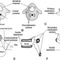
Carpal boss
The carpal boss is a bony excrescence off the dorsal wrist, which is a long known, but often overlooked cause of wrist pain ( Fig. 13 ). Although the etiology remains unclear, some have reported a posttraumatic cause of the deformity. Others believe it is a developmental anomaly known as the os styloidium; an accessory ossification center that is located in the area of the quadrangular trapezoid-capitate-metacarpal joint. The carpal boss varies in size and may be either completely isolated, or more commonly it is fused to the dorsal aspect of the second or third metacarpal, or occasionally to the capitate or trapezoid. Many patients with carpal bossing are asymptomatic. Symptomatic carpal boss ( Fig. 14 ) typically presents in the fourth decade with the dominant hand being more commonly affected. The altered biomechanics may result in overlying extensor tendinopathy, ganglion formation or bursitis, and eventually arthrosis. Treatment is surgical for those who fail conservative management, with wide excision of the carpal boss balanced with the risk of developing subsequent joint instability.
Type II lunate
The presence of a medial lunate facet that articulates with the hamate has been termed a type II lunate ( Fig. 15 ). The type II lunate configuration has a reported incidence of 44% to 77% and is associated with an increased incidence of chondromalacia in the proximal pole of the hamate. The size of this extra-articular facet ranges from 1 mm to up to 12 mm, with most in the 2- to 4.5-mm range.
The majority of wrists with a type II facet demonstrate no corresponding abnormality; however, cartilage loss, marrow edema, and subchondral cystic change on MR imaging indicate developing arthrosis ( Fig. 16 ). It has been shown that the incidence of proximal hamate chondromalacia at arthroscopy and gross dissection is greater than that reported by MR imaging alone, indicating that many cases are occult on MR imaging. This discrepancy may be caused by the relatively thin hyaline articular cartilage layers of the radiocarpal and intercarpal joints, resulting in difficulties in their visualization. When present, marrow edema in the proximal hamate is nonspecific and can be similar to that seen in patients with carpal contusion or fractures. However, in the presence of a type II lunate, chondromalacia should be strongly considered, particularly in the absence of trauma and when the edema is at the articulation of the hamate and lunate. Surgery has been shown to be beneficial in some patients with chronic wrist pain due to hamatolunate arthrosis. In 2 series of patients, resolution of symptoms was achieved following surgical resection of the diseased proximal pole of the hamate.
Related posts:
 Elbow Magnetic Resonance Imaging Variants and Pitfalls
 MR Imaging of the Hip: Normal Anatomic Variants and Imaging Pitfalls
 Magnetic Resonance Imaging Pitfalls and Normal Variations: The Knee
 Normal Variants and Pitfalls in MR Imaging of the Ankle and Foot
Bone Marrow
Normal Variants and Pitfalls in MR Imaging of the Ankle and Foot
Bone Marrow
 MR Imaging Features of Common Variant Spinal Anatomy
Stay updated, free articles. Join our Telegram channel

Full access? Get Clinical Tree


