Plain Radiographic Imaging
GENERATOR (THE POWER TO GENERATE X-RAYS)
DIAGNOSTIC X-RAY INTERACTIONS WITH MATTER
SCATTER RADIATION CONTROL FOR CONTRAST IMPROVEMENT
Concepts of Radiation
X-Ray Discovery
X-rays were discovered by Wilhelm Konrad Roentgen on November 8, 1895, in Würzburg, Germany. As he electrically activated a simple cathode ray tube, known as a Crookes’ tube, he happened to observe visible light emanating from a nearby plate coated with a phosphorescent substance, barium platinocyanide. Light emission increased as he brought the plate closer to the tube. He found that the newly discovered ray passed through objects of various compositions. Roentgen named the strange phenomenon x-light, with x representing the unknown. The name x-ray was later adopted, although some called it a “Roentgen ray” in honor of Roentgen.
Properties of X-Rays
Within months of Roentgen’s discovery, he had uncovered nearly every property of x-rays known today. X-rays have the following properties:
• They are a type of electromagnetic radiation (EM) with neither mass nor charge that travel in straight lines at the speed of light.
• They travel in packets, or bundles, called photons or quanta.
• They produce chemical and biologic effects in matter because of their ionizing capability.
• They cause certain materials to fluoresce.
• They sensitize radiographic and photographic film.
• They cannot be detected by human senses.
• They produce secondary and scatter radiation.
• They obey the inverse square law, which describes changes in intensity over distance.
• They are absorbed by heavy, dense materials, such as lead and cement.
• They have a wave and particle dual nature.
• Because of their extremely short wavelengths, they penetrate materials that normally absorb or reflect light.
• They cannot be focused by a lens.
X-ray is a form of EM that is produced when high-speed electrons in an electric circuit interact with a hard metal surface. The interaction takes place at the subatomic level and involves the electrical attributes of an atom.
Atomic Structure
In 1913, the German physicist Niels Bohr compared the atom to a miniature solar system. Current theories have evolved beyond the Bohr model; however, Bohr’s theory works well for illustrating and understanding atomic forces. Basically, Bohr described the atom as having a dense core, or nucleus, made up of neutrons and positively charged protons. Negatively charged electrons, spinning on their axes, orbit the nucleus at fixed distances called quantum shells or energy levels. Quantum shells are assigned the letters K, L, M, N, and so on, with K being the innermost shell (Fig. 1-1). Electrons occupying shells farther away from the nucleus have greater potential energy than those found closer to the nucleus.
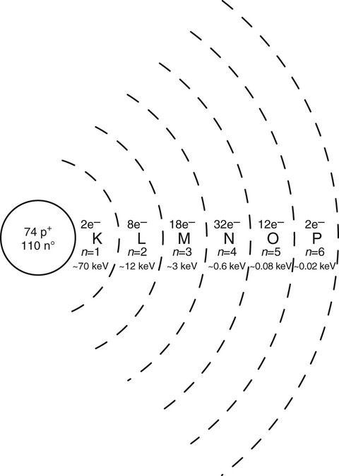
In a neutral atom, the number of protons in the nucleus, or atomic number (Z), is equal to the number of orbiting electrons. The maximum number of electrons occupying a given shell is determined by the formula 2n2, where n is the quantum shell number. The quantum shell number is obtained by counting the shells outward from the nucleus. The K shell (n = 1) can hold 2(1)2, or two, electrons; the L shell (n = 2) can hold 2(2)2, or eight, electrons; and so on. The outermost shell, or valence shell, never exceeds eight electrons at one time in a stable atom.
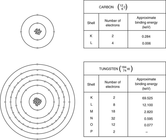
Positively charged nuclear protons exert an electrostatic attractive force binding electrons to their orbit. Electron spin velocity counters the attractive force and keeps electrons at discrete distances from the nucleus. Electrons occupying shells closer to the nucleus are bound tighter. The amount of energy needed to remove an electron completely from its orbit is called electron binding energy. Electron binding energy is measured in electron volts (eV), the same unit used to describe x-ray energy. A free electron is assumed to have zero binding energy; therefore, a bound electron is in a negative energy state because it takes positive energy to unbind or raise the binding energy to zero. Electrons occupying shells closer to the nucleus have greater binding energy than those found farther from the nucleus. The binding energy for any given electron increases as atomic number increases (Fig. 1-2).
Radiation
Energy is defined as the ability to do work. When energy is transmitted through space or matter, it is called radiation. Radiation takes many forms, such as heat, light, sound, and x-ray. Its energy often is described as the ability or inability to ionize matter. Ionizing radiation possesses sufficient energy to remove an orbital electron from a stable atom or molecule. X-rays and gamma rays and alpha and beta particles are examples of ionizing radiation. Nonionizing radiation falls short of causing ionization; however, it may excite stable atoms by raising an orbital electron to a higher energy state. This type of radiation includes visible light, infrared rays, microwaves, and radio waves. Ionizing radiation is categorized as either particle or EM.
Particle Radiation.
Particle radiation is made up of any subatomic particles, such as protons, neutrons, and high-speed electrons, capable of causing ionization. Alpha and beta particles are two of the more common types of particle radiation. They come from the nuclei of radioactive atoms through radioactive decay. Particle radiation has a mass component, may have a charge, and travels at varying speeds (slower than the speed of light).
Electromagnetic Radiation.
Electromagnetic radiation is an electric and magnetic disturbance traveling through space at the speed of light (2.998 × 10⁸ m/s). It contains neither mass nor charge but travels in packets of radiant energy called photons, or quanta. Examples of EM radiation include radio waves and microwaves, as well as infrared, ultraviolet, gamma, and x-rays. Some sources of EM radiation include sources in the cosmos (e.g., the sun and stars), radioactive elements, and manufactured devices. EM exhibits a dual wave and particle nature.
Electromagnetic radiation travels in a waveform at a constant speed. The wave characteristics of EM radiation are found in the relationship of velocity to wavelength (the straight line distance of a single cycle) and frequency (cycles per second, or hertz, Hz), expressed in the formula

where c = velocity, λ = wavelength, and v = frequency.
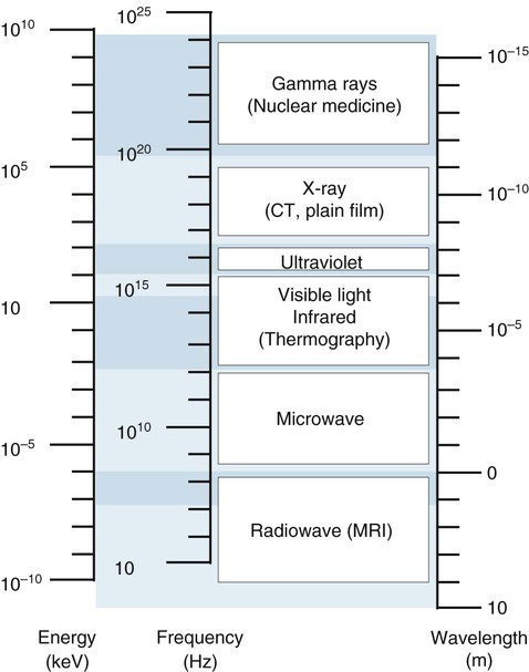
Because the velocity is constant, any increase in frequency results in a subsequent decrease in wavelength. Therefore, wavelength and frequency are inversely proportional. All forms of EM radiation are grouped according to their wavelengths into an electromagnetic spectrum, seen in Figure 1-3.
The particle-like nature of EM radiation manifests in the interaction of ionizing photons with matter. The amount of energy (E) found in a photon is equal to its frequency (ν) times Planck’s constant (h):

Photon energy is directly proportional to photon frequency. Photon energy is measured in eV or keV (kilo-electron volts). The energy range for diagnostic x-rays is 40 to 150 keV. Gamma rays, x-rays, and some ultraviolet rays possess sufficient energy (>10 keV) to cause ionization.
The energy of EM radiation determines its usefulness for diagnostic imaging. Because of their extremely short wavelengths, gamma rays and x-rays are capable of penetrating large body parts. Gamma rays are used in radionuclide imaging. X-rays are used for plain film and computed tomography (CT) imaging. Visible light is applied to observe and interpret images. Magnetic resonance imaging (MRI) uses radiofrequency EM radiation as a transmission medium (see Fig. 1-3).
Radiation Units of Measurement
Four units used to measure radiation are the roentgen (R), rad, rem, and curie. The roentgen is a measurement of radiation exposure, or intensity, which creates 2.08 × 10⁹ ion pairs in a cubic centimeter (cm3) of air. The SI system (Système Internationale d’Unites) is a modernized metric system based on meters, kilograms, and seconds or centimeters, grams, and seconds. The SI units are used more broadly in science and most countries of the world than are the British, or Customary, units of feet, pounds, and seconds. The SI unit for radiation exposure is coulombs/kilogram (C/kg); 1 roentgen is equal to 2.58 × 10⁻⁴ C/kg. Radiation exposure emitted from x-ray machines is measured in roentgens or C/kg.
The rad is the unit that measures absorbed dose. It is a measure of energy (expressed in ergs) deposited into a mass of tissue (expressed in grams or kilograms) and is often related to the biologic effects of radiation. One rad is equal to 100 ergs in 1 g of irradiated tissue. The SI unit for absorbed dose is the gray (Gy). One gray is equal to 100 rads. One rad is equal to 0.01 gray or 1 centigray (cGy).
The unit that defines absorbed dose equivalent for humans is the rem (rad equivalent man). The rem is used exclusively for radiation protection reporting of occupational exposure. It is a measure of the biologic effectiveness of different types of radiation in humans. Compared with x-rays and gamma rays, particle radiation such as alpha and beta particles and fast neutrons produces different magnitudes of biologic effects even at the same absorbed dose.
The National Council on Radiation Protection and Measurements (NCRP) is the U.S. governing body responsible for reporting guidelines for radiation protection and measurements. The most recent report, NCRP No. 116: Limitations of Exposure to Ionizing Radiation, which succeeds NCRP Report No. 91, replaces the term dose equivalent (H) with the term equivalent dose (HTR). The change goes beyond word semantics. Dose equivalent (H) is a measurement of absorbed dose at some certain location in tissue. Equivalent dose (HTR) is a measurement of an average absorbed dose in tissues and organs. Equivalent dose is the product of the average absorbed dose (DTR) of radiation (R) in a tissue (T) and a radiation weighting factor (WR):

The weighting factor replaces the previously used quality factor (QF) and accounts for the biologic effectiveness of specific types of radiation. The weighting factor for x-rays and gamma rays is 1; 1 rad of x-rays is equal to 1 rem in soft tissue. Alpha particles have a WR of 20; 1 rad of alpha particles is equal to 20 rems. The SI unit for the rem is the sievert (Sv). A sievert is the product of the absorbed dose in grays and the radiation weighting factor. One Sv is equal to 100 rems, and 1 rem is equal to 10 mSv.
The curie (Ci) is a quantitative measure of radioactive material. It is defined as the amount of radioactive material in which 3.7 × 10¹⁰ atoms disintegrate every second. The radiation emitted from a curie of radioactive material is measured in roentgens, rads, and rems. The SI unit is the becquerel (Bq), defined as 1 disintegration per second. Millicurie (mCi) and microcurie (µCi) amounts are common in nuclear medicine procedures. The reporting units used in the radiologic sciences are listed in Table 1-1.
X-Ray Tube
Producing x-rays requires a source of electrons, a means to rapidly accelerate them, and a means to rapidly decelerate them. These factors are built into the x-ray apparatus. The three principal components of an x-ray machine are the x-ray tube, generator, and control console.
Tube Housing
The tube housing is a grounded, lead-lined metal shelter that protects and supports the glass x-ray tube insert (Fig. 1-4). X-rays are emitted multidirectionally from the tube, but only those rays passing through an opening, or port window, in the housing expose the patient. All other rays are trapped in the housing wall, thereby decreasing unnecessary exposure to patients or x-ray personnel. Radiation emitted from the tube housing is called primary radiation.
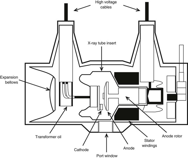
Several high-voltage electrical cables connect through the back of the housing to the tube. The housing is factory packed with industrial grade oil to provide thermal and electrical insulation. Many modern x-ray machines have tube protection circuitry hooked into an expansion bellows inside the housing. As the oil expands with heating, the bellows trips a switch, which prohibits further exposure until the tube cools sufficiently. Industrial x-ray tubes may have a large heat exchanger that circulates and cools the oil.
Glass Envelope
X-rays are produced when high-speed electrons are rapidly decelerated in an x-ray tube. The x-ray tube is a device composed of two electrodes, cathode and anode, sealed in an evacuated borosilicate glass envelope. Electrons in an electric circuit, generated at the cathode, are accelerated toward and strike an anode target, which results mostly in heat energy and some x-ray energy. Approximately 1% of the kinetic energy of high-speed electrons produces x-rays.
Cathode.
The cathode is the negative electrode and contains a filament embedded in a shallow depression called the focusing cup. Most diagnostic x-ray tubes are dual focus because they have two filaments: a large filament for exposures of high intensity and a small filament for exposures of low intensity.
The cathode filament supplies a controlled number of electrons to the anode. The filament is a thoriated tungsten wire drawn into a small, thin coil. Tungsten is used because its high atomic number (74) makes it electron rich. Current running through the filament heats it to white incandescence, which results in electrons being “boiled off” the tungsten by a process called thermionic emission. A cloud of electrons, or space charge, forms around the filament (Fig. 1-5). The space charge size is controlled by the amount of current running through the filament. Filament current is regulated by the mA (milliampere) selector on the control console. The space charge generates tube current (mA), current between the cathode and anode. The amount of tube current (mA) produced is directly proportional to radiation exposure or quantity of x-rays produced.
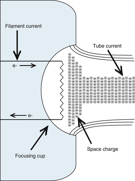
Electrons travel in only one direction in the tube, from cathode to anode. As the space charge builds, electrons repulse each other. This causes them to diverge, covering an unacceptable area on the anode. A focusing cup surrounding the filament carries a negative potential that tends to condense or “focus” the electron stream onto the anode target.
Anode.
The anode is the positive electrode in the x-ray tube. The anode (1) produces x-rays, (2) conducts electricity, and (3) conducts heat away from the anode surface.
There are two types of anodes: stationary and rotating. Most diagnostic applications require the rotating type. The stationary anode is most applicable when a smaller electrical load is necessary for imaging (e.g., mammograph and dental radiograph).
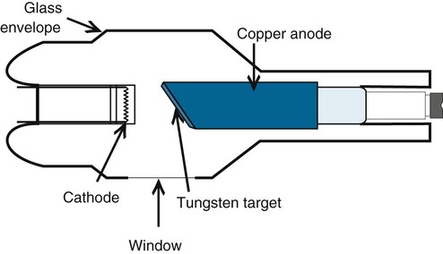
A stationary anode consists of a copper shaft with a tungsten–rhenium target imbedded into a beveled surface (Fig. 1-6). Tungsten is used because of its high melting point (3410°C) and its high atomic number (74). The atomic number affects the ability of tungsten to produce x-rays in the diagnostic range. The beveled or angled surface affects the electron-loading capacity of the anode by providing more surface area for heat conduction. The angle on stationary anodes ranges from 30° to 45°. The most common angle used on rotating anodes is 12° with a useful range of 7° to 17°.
A rotating anode allows significantly greater electron loading by providing a much larger surface area, or focal track, for heat conduction. The rotating anode consists of three component parts: (1) disc or target, (2) stem, and (3) rotor.
The disc is made of molybdenum and is covered with a tungsten–rhenium target material. An electromagnetic induction motor is used to rotate the anode disc an average of 3400 revolutions per minute (rpm) during the exposure, with high-speed anodes rotating up to 10,000 rpm. Tube electron loading is directly proportional to anode rotation.
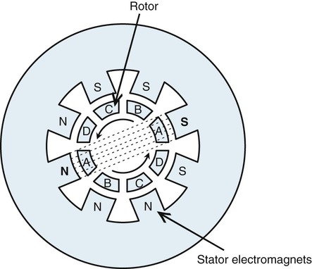
The stem connects the disc to the rotor and is made of copper for electrical conduction. The rotor is a shaft-like part composed of bars of copper around a soft iron core. The rotor is held in place in the tube by bearings that facilitate high-speed rotation. Outside the evacuated glass tube and adjacent to the rotor is a series of pairs of electromagnets called a stator. Current running through the stator creates a magnetic field that crosses the rotor. The pairs of electromagnets are sequentially energized by multiphase current, creating a rotating magnetic field that turns the rotor (Fig. 1-7).
Anode rotation is initiated by depressing the rotor or “prep” switch on the control console before activating the exposure. The filament circuit also is wired into the rotor switch so that filament current is boosted to preset levels at the time the rotor switch is depressed. Rotor speed and space charge are generated first in anticipation of the exposure. Depressing the exposure switch causes electrons to move instantaneously from cathode to anode.
With many x-ray machines, the exposure switch alone activates all electronic functions in the tube: rotation of the anode, creation of the space charge, and movement of electrons from cathode to anode. However, two-handed operation of the rotor and exposure switches allows the operator to control exactly when exposure occurs. Single-handed operation of the exposure switch alone is best when very fast exposure time (milliseconds) is used.
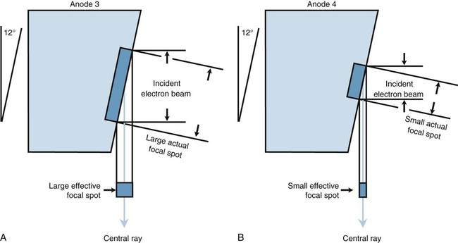
Line-Focus Principle
Electrons strike the surface of the anode at a target site called the actual focal spot (Fig. 1-8). An increase in either filament length or anode angle results in an increase in actual focal spot size. As the focal spot size is increased, the electrical loading capacity of the anode is increased, which safely allows exposures that require higher electrical loads. Although the entire target area emits x-rays, only the rays traveling in the direction of the patient are useful. The line-focus principle is used to reduce the effective area of the actual focal spot to that portion of the x-ray beam that is useful. The effective target area, or effective focal spot, is a measure of the width of the actual focal spot projected along the central ray and perpendicular to the plane of the x-ray port. As with the actual focal spot, the size of the effective focal spot is determined by the size of the filament and angle of the anode (see Fig. 1-8). Tube specifications typically include the effective focal spot size, a measurement related to overall image resolution (clarity). In general, the smaller the effective focal spot size, the better the resolution. Effective focal spot sizes commonly used in diagnostic radiology range from 0.6 to 1 mm for small focus and 1.5 to 2 mm for large focus.
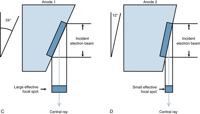
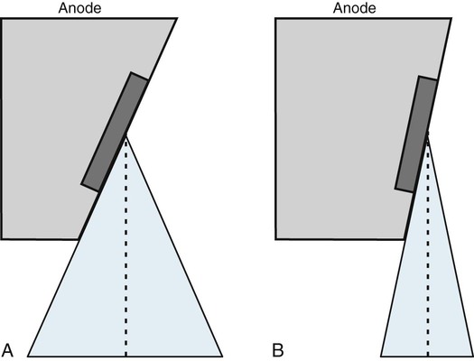
The anode angle on a rotating anode tube also determines maximum field coverage when the tube is placed at specified tube distances (Fig. 1-9). A standard angle of 12° is used for sectional imaging to cover 17 inches2 at a 40-inch focal-spot-to-film distance. A 14° angle is needed to cover 36 inches2 at a 72-inch focal-spot-to-film distance for scoliosis screening and other full-spine imaging needs.
Focal spot selection is linked to specific mA stations on the control console. For example, the small focal spot is coupled with mA stations below 200 mA on most diagnostic x-ray machines. This limits the load on the anode and is best used with small body parts, such as the cervical spine and extremities. The large focal spot is coupled with the 200 mA and higher station to allow for greater electron loading of the anode. It is best used with large body parts, such as the lumbar spine. The small focus produces images with better detail than the large focus.
Off-Focus Radiation
Off-focus radiation results from rebounding electrons from the focal spot striking other areas of the anode, thereby producing a large low-intensity x-ray source. This extra-focal radiation increases patient dose and image blurring from shadowing and decreases image contrast. Patient anatomy appearing outside of the exposure field (e.g., ears on a skull examination) is attributed to off-focus radiation. The upper fixed shutters of a collimator (beam-limiting device) help reduce the amount of off-focus radiation reaching the film.
Heel Effect
X-ray intensity emanating from the tube is not uniform across the span of the beam. Exposure intensity is greater on the cathode side of the x-ray beam than the anode side. This is called the anode heel effect. Electrons penetrate the target at various depths, causing x-rays to be emitted with equal intensity in all directions. X-rays traveling into the substance of the anode are immediately absorbed. The angle at which x-rays emerge from the target surface toward the patient varies and causes some x-rays to be absorbed in the heel of the anode. The heel attenuates a portion of the x-ray beam and leaves less exposure (intensity) on the anode side of the beam (Fig. 1-10).
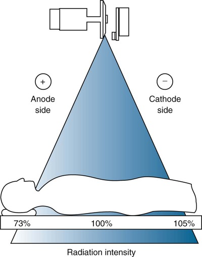
When body parts of different thicknesses are imaged, the heel effect can be used to advantage if the cathode portion of the x-ray beam is placed over the thickest part of the patient. The heel effect is less noticeable with smaller film sizes (8 × 10 inch) and longer tube distances (72 inch) because more of the central, uniform portion of the beam is used.
Filtration
Very-low-energy x-rays, or soft rays, add no diagnostic information to the image because they are completely absorbed by the patient. To reduce patient dose from soft radiation, federal law requires a minimum of 2.5 mm equivalent of aluminum (equiv/Al) filtration for a beam greater than 70 kVp. Aluminum absorbs many of the low-energy photons while transmitting a large proportion of high-energy photons. The glass port window and oil within the tube housing provide inherent filtration of approximately 0.5 mm equiv/Al. The silver-coated mirror in the collimator is placed so that the x-ray beam must pass through it. It may supply another 1 mm equiv/Al of inherent filtration.
Another 2 mm of aluminum is added to most diagnostic x-ray machines to meet federal guidelines for total filtration. Inherent filtration plus added filtration equals total filtration. Compensating filters, used to offset variations in patient density, are not calculated into the total filtration needed to decrease the soft x-ray dose.
Generator (The Power to Generate X-Rays)
The electrical potential needed to accelerate electrons to high speed in the tube is provided by single-phase, three-phase, and constant potential (high-frequency) generators. The scope of this chapter does not permit a detailed discussion on how these generators work; however, one must understand that the output waveform affects average x-ray energy, exposure time, and patient dose from soft radiation.
Alternating current (AC) is dispensed to the x-ray machine from an external source, but it is changed to direct current (DC) before it reaches the tube. AC manifests in electrons oscillating back and forth in a circuit and is graphically represented in Figure 1-11 by a sine wave. Each cycle of single-phase AC comprises a positive and negative pulsation. Running AC through the tube creates two problems: (1) it destroys the cathode when electrons reverse polarity during the negative pulsation, and (2) a secondary site for x-ray production is generated and negates any advantage of increased image detail produced by the line-focus principle.
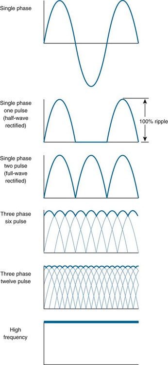
Alternating current is changed to DC through a process called rectification. For the purpose of this chapter, how rectification occurs is less important than why it occurs. Suppressing the negative pulsation of AC protects the tube and results in a type of pulsating DC called half-wave rectification (see Fig. 1-11). X-ray energy is produced at the peak of these pulsations (Fig. 1-12). Reversing the negative pulsation to a positive direction provides full-wave rectification, resulting in twice the number of pulsations per unit of time. This reduces the exposure time by half compared with half-wave rectified circuits.
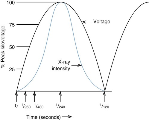
X-rays are produced when electrons strike the target at or near their peak potential, or kilovolt peak (kVp). In the case of full-wave rectified circuits, bursts of diagnostic hard x-rays are produced when the electrical potential reaches its peak with periods of lower energy (soft) or no x-rays produced between the peaks. The voltage drop from kVp is called ripple and represents the efficiency at which x-rays are produced. The greater the ripple, the less efficient the x-ray production. A kVp of zero accompanies 100% ripple. A voltage potential that drops below peak kilovoltage produces x-ray photons with a wide spectrum of energies.
Single-Phase Generators
Single-phase, full-wave rectified generators use a 220-volt, 100-amp, single-phase AC line source to produce two pulsations per cycle (120 pulsations per second) with 100% voltage ripple. With a constantly changing voltage potential, a spectrum of x-ray energies is produced with an average energy somewhere below peak kilovoltage. This pulsating beam results in an inefficient use of electricity, longer exposure time, and greater patient dose from lower energy soft x-rays compared with more efficient generators that deliver a nonpulsating, constant electrical potential.
Three-Phase Generators
A three-phase generator uses a three-phase AC line source for the purpose of creating more pulsations per unit time. This effectively reduces voltage ripple and increases the efficiency of x-ray production. Three-phase power is best understood by imagining three single-phase line sources electrically intertwined to create greater incoming power. A six-pulse generator delivers six pulsations per cycle, which reduces voltage ripple to 13% of kVp (see Fig. 1-11). Changing the wiring configuration produces 12 pulses per cycle (12-pulse generator), reducing voltage ripple to 3% of kVp. Using three-phase power results in greater photon output per unit of electrical input (mR/mAs) with higher average energy compared with single-phase units. Three-phase generators are expensive and rely on costly power line installations.
Constant Potential Generators
Medium- and high-frequency generators operate on either single- or three-phase power and eliminate voltage ripple through rectification and smoothing circuits. Medium-frequency generators produce an electrical frequency in the 6- to 30-kHz range, and high-frequency generators produce an electrical frequency of approximately 100 kHz. Medium- and high-frequency generators allow more accurate control of tube voltages. Tube voltage regulates penetration of the x-ray beam. High-frequency generators deliver the greatest mR/mAs output, the lowest soft radiation dosage to patients, the highest average (effective) x-ray energy, and the shortest exposure time.
Timer Control
Every x-ray exposure requires a certain predetermined tube current (mA) for a specific period of time. Both the timer and timer circuit are located on the control console and are electrically connected to the exposure switch.
An electronic timer is the most common timer in use today. It is accurate to less than 1 millisecond (msec) and to greater than 1 second. Electronic timers operate on sophisticated electronic circuitry by energizing a silicon-controlled rectifier (SCR), which activates the exposure. The combination of constant potential generators and very fast imaging systems (rare earth) require a timer accurate in milliseconds.
The product of mA and time, milliampere-seconds (mAs), determines the number of x-ray photons emitted and hence the relative darkness of the film. Patient part size and density govern how many mAs are needed to produce a diagnostic image. Calculating exposure by using units of mAs is common in a clinical setting. An mAs timer accurately provides the highest safe tube current with the shortest exposure time for a given mAs. Independent control of mA and time may not be possible with some mAs timers.
Automatic Exposure Control
Automatic exposure control (AEC), often called phototiming, terminates the exposure when a predetermined amount of film density (darkness) is reached by x-rays passing through the patient to the image receptor. The radiographer selects the appropriate beam penetration (kVp) and desired tube current (mA) for the part under examination. The phototiming device senses the exposure and, in response, creates an electronic signal that breaks the timer circuit.
Automatic exposure devices include the earlier photomultiplier tube and the more common ionization chamber. The photomultiplier tube converts a light signal from a fluorescent screen exposed to x-rays to an electronic signal that feeds back to terminate the exposure. The radiation-sensitive ionization chamber creates an electronic signal proportional to the number of ions produced by radiation exposure and feeds back to terminate the exposure.
The phototiming circuit usually has one, two, or three photocells of different shapes and positions in relation to the image receptor. From the control console, the operator may choose to use one or more photocells to determine exposure. When more than one photocell is used, the exposure is averaged between them. A manual backup timer is set to approximately 1.5 times the anticipated exposure to prevent tube overload and excessive patient dose. Setting the backup time too short may result in a risk of underexposure.
Automatic exposure control decreases the need for repeat radiographs by adjusting for patient density and reducing human error in exposure calculation. However, positioning the body part under examination precisely over the photocell(s) is paramount to produce adequate exposure. Malposition results in overexposure or underexposure. Exposure area also affects the photosensor readings, especially considering scatter radiation production; therefore, proper beam collimation is necessary to produce accurate exposure time. The calibration of the phototimer must be matched with the sensitivity of the image receptor (film/screen).
Tube Failure
X-ray tubes can fail in a number of different ways. Most tube failure occurs as the result of thermal wear on the internal component parts. The wear usually develops over a period of time; however, an instantaneous load significantly above the tube rating can cause a tube to fail immediately. Common types of tube failure include worn rotor bearings, a cracked or pitted anode, gassing of the tube, and an open cathode filament.
To better prepare the tube to receive a high heat load, it is best to perform a tube warm-up procedure. Executing a couple of low-load exposures puts some heat into the anode and reduces the stress of an instantaneous large load on a cold anode. An example of a warm-up technique is an initial exposure of 50 kVp, 100 mA, at 1/30 second followed by a second exposure in which the mA is raised to 200. Other ways to maximize x-ray tube life include:
• Minimize filament boost (preparation) time.
• Limit rotor/start/stop operations.
• Use lower tube current (mA).
• Do not make a high mA exposure on a cold tube.
• Adhere to rating charts and anode heating and cooling curves.
• Limit operations to 80% of maximum single exposure ratings.
• Do not exceed the anode thermal capacity or dissipation rate of the target.
Primary Factors Controlling X-Ray Exposure
Four primary exposure factors control the quantity and quality of x-ray films produced: peak kilovoltage, mA, time (seconds), and distance.
1. Kilovoltage (expressed in kVp) directly controls the speed of electrons traveling from cathode to anode. As electrons strike the target, their kinetic energy is transformed into x-ray and heat energy. X-ray quality, or penetration power, is directly proportional to kVp. Kilovoltage is the only controlling factor affecting x-ray beam energy (quality). Kilovoltage is responsible for providing the penetration necessary to produce adequate subject contrast.
2. Milliampere (measured in mA) is a measure of tube current generated from the filament by thermionic emission. The number of electrons available to produce x-rays is directly proportional to mA. Changes in mA affect the quantity of x-rays produced. Milliampere output is linear; as mA is doubled, exposure is doubled.
3. Exposure time is another factor controlling the number of x-rays (quantity) produced. Time is measured from milliseconds to seconds and is given the abbreviation “s”. Longer exposure time allows more electrons to be generated from the filament. Exposure time is also linear in that exposure is doubled as time is doubled.
In clinical settings, exposure intensity (quantity) is commonly controlled by the product of milliamperes and time, or mAs. Ascribing mAs to a particular body part size is helpful in determining the total exposure needed to produce an acceptable image. After the measurement of mAs is determined, any combination of milliampere and time to produce that same measurement of mAs yields a similar exposure. The mAs controls the relative darkness of the film.
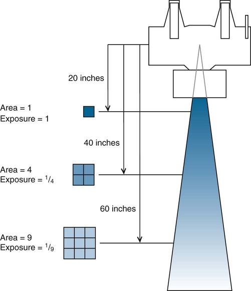
4. Distance, the fourth exposure parameter, is often expressed as FFD (focal-film distance), SID (source-to-image receptor distance), and TFD (tube-film distance). Distance affects the number of x-rays reaching the image receptor (film). As the x-ray tube is moved farther away from the film, the beam diverges and offers less x-ray photons per unit area. The number of x-ray photons striking the film is inversely proportional to the square of the distance. This is called the inverse square law and is expressed as

where I = x-ray intensity and d = tube distance. If the distance is doubled, approximately 1/4 of the number of x-rays reaches the film (Fig. 1-13).
Whereas x-ray beam intensity is inversely proportional to the square of the distance, tube load (mAs) is directly proportional to the square of the distance. An increase in distance mandates an increase in tube load expressed by the formula

where FFD1 is the original distance, FFD2 is the new distance, old mAs represents exposure (tube load) at the original distance, and new mAs represents exposure (tube load) at the new distance.
Control Console
Basic single-phase operating consoles (Fig. 1-14) provide selectors for power (on/off), line-voltage compensation, peak kilovoltage, milliampere, time, focal spot, Bucky (see Grids), AEC, rotor, and exposure.
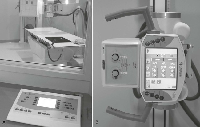
Control consoles have evolved with the use of computer technology. Manufacturers have reduced console size by replacing copper wiring, steel construction, and knob controls with microcircuitry. Menu-driven push-button controls, preprogrammed anatomic techniques, and AEC have dramatically reduced human error in the calculation and selection of exposure parameters.
Modern single-phase 300 mA/125 kVp x-ray machines may offer any or all of the following:
• Automatic line-voltage compensation (voltage fluctuation control)
• Kilovoltage selection by units of 1 kV, from 40 to 125 kVp
• Milliampere selection normally ranging from 25 to 300 mA and as high as 600 mA in 50- to 100-mA increments
• Automatic focal spot selection based on milliampere designation
• Electronic SCR timers with milliampere-seconds readout
• AEC with photocell selector and plus and minus density control
• Bucky selection
• Single- or double-switch operation of rotor control and exposure control
• Tube protection circuitry to safeguard against overload
X-Ray Production
X-rays are generated by two different yet simultaneous processes as high-speed electrons lose energy at the target. One reaction involves high-speed electrons interacting with the nucleus of tungsten target atoms to generate what is called bremsstrahlung radiation. The other involves collisions of high-speed electrons with inner shell electrons of target atoms to produce what is called characteristic radiation.
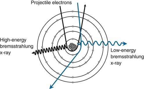
Bremsstrahlung Radiation
Bremsstrahlung is the German word for braking, or slowing down. When a high-speed projectile electron from the cathode passes the nucleus of a tungsten atom in the target, the positively charged nucleus exerts an attractive force on the electron. A strong nuclear electric field inhibits penetration of the electron into the nucleus but causes the electron to decelerate and change direction (Fig. 1-15). This deceleration results in a loss of kinetic energy, which is converted into EM (x-rays). The quality (or energy) of radiation released is contingent on the amount of deceleration and kinetic energy possessed by the incoming electron (measured in kVp). Deceleration is affected by the proximity in which electrons randomly approach the nucleus and size of the nucleus. Electrons directly striking the nucleus and giving up 100% of their kinetic energy generate the highest energy x-rays.
Bremsstrahlung x-rays have a spectrum of energies with an average energy somewhere below, but proportional to, the peak kilovolts used. Primary control of x-ray beam quality, or overall penetrating power, is a result of the effect of peak kilovolts on bremsstrahlung interactions. The quantity of bremsstrahlung x-rays is related more to milliampere-seconds (tube current) than peak kilovolts. Higher values of milliampere-seconds release more electrons to the target. Most of the x-rays produced in a diagnostic beam are of bremsstrahlung origin.
Characteristic Radiation
When a high-speed electron from the cathode interacts with a lower orbit (inner shell) electron in the tungsten target and the kinetic energy of the projectile electron exceeds the binding energy of the electron it interacts with, the orbital electron is ejected, leaving a vacancy in the inner shell (Fig. 1-16). Immediately, an upper orbit electron fills the vacancy, resulting in a release of a discrete amount of EM (x-ray). The amount of energy released is equal to the difference in the binding energies of the orbital shells involved. For tungsten, atomic number 74, the following applies:
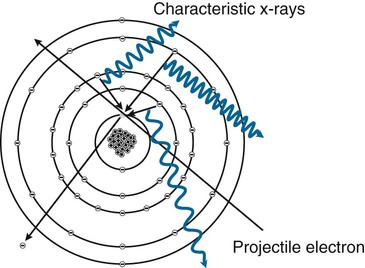
EKshell−ELshell=69.5keV−12.1keV=57.4keV x−ray

A cascade effect causes all inner shell vacancies to be filled and lower energy photons to be released. The total amount of energy released equals the input energy necessary to remove the inner shell electron.
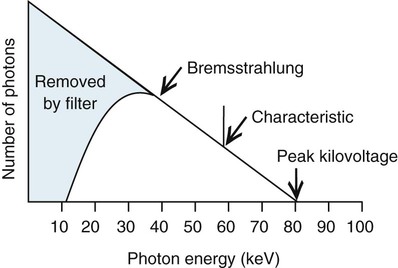
Binding energies are unique to each element. The radiation released is “characteristic” of the atom it is generated from, hence the name characteristic radiation. A K-characteristic x-ray of tungsten is 57.4 keV. A K-characteristic x-ray of molybdenum is 17.4 keV. It takes at least 70 keV (kVp) of input energy to release a K-shell electron in tungsten. Kilovoltage has no effect on the quality (energy) of characteristic radiation. However, the energy of characteristic x-rays increases as atomic number increases. Characteristic x-rays make up approximately 10% of the radiation emitted in the 80- to 100-kVp range. Figure 1-17 illustrates a filtered beam of bremsstrahlung and characteristic x-rays at 80 kVp.
Related posts:


Stay updated, free articles. Join our Telegram channel

Full access? Get Clinical Tree


