Numerous methods of investigating the skeletal system are available. (
Table 7-1) Each modality has its own area of specific use and specialized information. Usually a number of these are used in combination to provide the necessary information for arriving at an accurate diagnosis.
Plain Film Radiography
Applications.
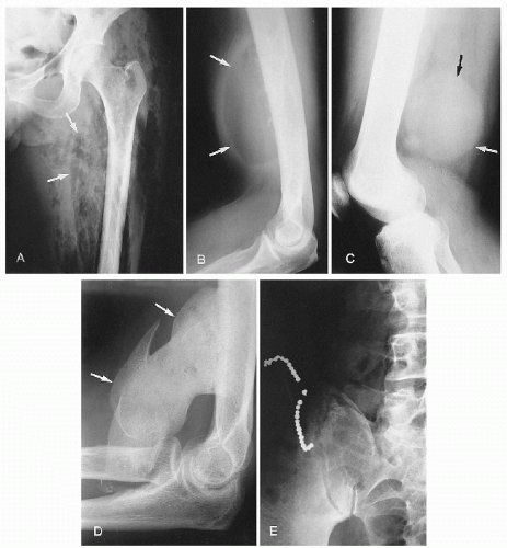
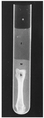
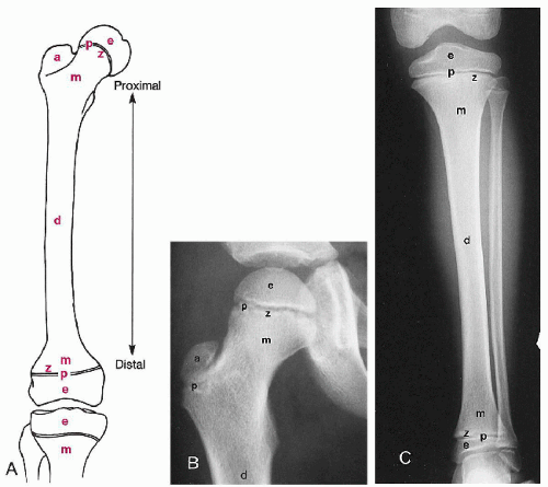
Plain film radiography is the most widely used skeletal imaging method. No contrast media is used to enhance various body structures. The visualization of these components depends on the natural contrast between the five radiographic densities—air, fat, water, bone, and metal. (
Figs. 7-1 and
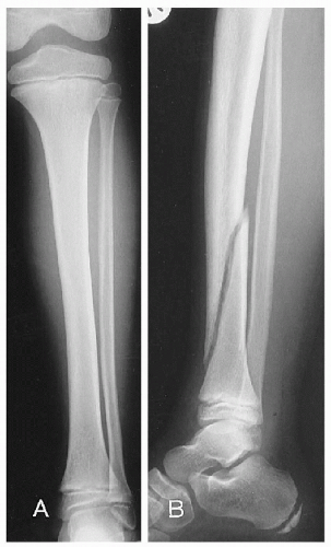
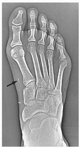
7-2) A basic premise in plain film evaluation is the absolute necessity of having a minimum of two views, preferably perpendicular to each other. (
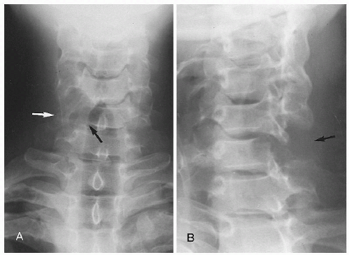
Fig. 7-3) These should be supplemented with additional projections, such as oblique, angulated, or stress studies, as clinically indicated. (
1) (
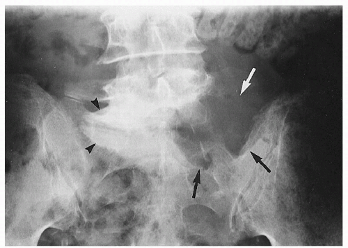
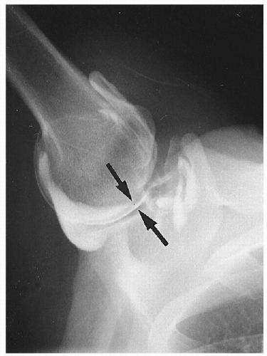
Figs. 7-4 and
7-5)
Considerable conflict has arisen in more recent times over the indications for skeletal radiography—particularly in the spine—as concerns for radiation safety, public health, and rising healthcare costs have gained momentum. Guidelines have been developed to assist in the imaging decision-making process. (
2,
3,
4,
5,
6) (
Table 7-2)
Applications of skeletal radiography are numerous. It is often the initial investigation of skeletal abnormalities and provides pivotal information regarding any additional imaging modality that may be indicated or contraindicated. Recognition of a definite diagnosis is frequently possible or at least a short list of differential
diagnoses can be determined. In addition, plain films are important for comparison of changes in the disease process over time or with therapy and provide incidental detection of unsuspected bony and soft tissue abnormalities. Biomechanical information can be gleaned from functional stress radiographs obtained at extremes of motion, on weight bearing, or with the application of compression-distraction forces. (
7)
Advantages.
Conventional radiographic studies are readily available, relatively inexpensive, and non-invasive. They depict anatomic details in a format that is readily understandable and requires relatively few anatomic computations for the understanding of three-dimensional relationships. Key benefits are the demonstration of bony landmarks and the ability to assess contiguous structures over considerable length.
Disadvantages.
The major drawbacks consist of the lack of soft tissue discrimination, diminished sensitivity in detecting bone density changes, resolution of small lesions, radiographic latent period, variability and effect of exposure differences, technical artifacts, and exposure to ionizing radiation.
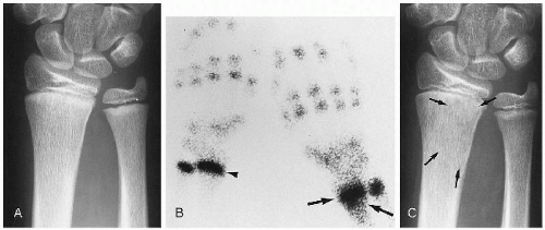
Soft tissue depiction is limited to definition of anatomic planes determined largely by surrounding fat. Diagnostic sensitivity can be limited; up to 30-50% loss of bone density and a lesion size of at least 1-5 cm are often necessary before a structure is visible on a radiograph. (
8,
9,
10) In this context the patient may have extensive histologic disease and have a normal-appearing radiograph. (
Fig. 7-6) Similarly, the time interval from when the disease process manifests clinically until it becomes visible radiographically can be quite long. This is referred to as the
radiographic latent period. Osteomyelitis in a peripheral bone takes a minimum of 10-14 days before it can be seen on the plain film, whereas in the spine this can take 21 days. Tumors may be expected to be slower than infections to manifest, though aggressive lesions can manifest within 4-6 weeks.
Tomography
The word
tomography is derived from the Greek
tomos, which means “a cutting.” Tomography involves visualizing a selected anatomic layer and has been called
laminography and
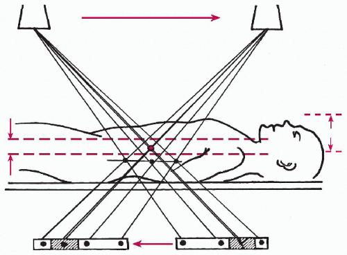
zonography. Essentially it permits the detailed examination of anatomy and abnormalities that are inaccessible by conventional radiography, allowing selective imaging at any selected level in the body. The level to be imaged is set at the fulcrum between the x-ray tube and film cassette, which move in opposite directions during the exposure. (
Fig. 7-7) The movement may be linear or hypocycloidal. The effect is to produce a sharp, in-focus image at the level of the fulcrum while blurring out those structures above and below. Sequential films are taken at varying fulcrum levels to totally evaluate the structure in question.
Applications.
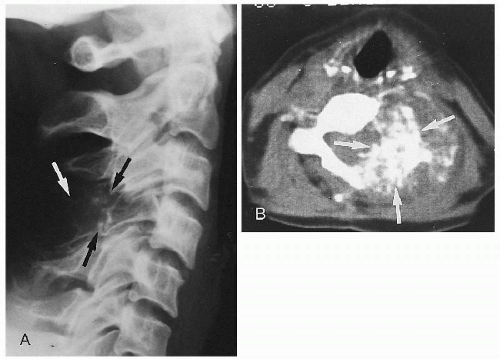
Tomography is especially useful in the evaluation of such complex structures as the skull and spine; in addition, it delineates the site, characteristics, and extent of a bony abnormality. (
Fig. 7-8)
Advantages.
Tomography is beneficial when overlying structures obscure a lesion. Subtle fractures and early bone destruction can be identified when plain films are normal. Complex anatomic deformities of the spine and pelvis can be readily analyzed with tomography.
Disadvantages.
High radiation dose is the single greatest handicap because multiple exposures are required. Furthermore, long exposure times are required to allow for tube-cassette motion, which allows for patient motion artifacts. Enough slices must be obtained at thin intervals, otherwise lesions will be overlooked. Soft tissue planes are more readily identifiable, but internal structure is not visible as a rule.
Xeroradiography
Xeroradiography is different from conventional radiography in that it uses an electrically charged selenium plate as the “cassette.” When x-rays strike the plate, the charge is lost. A fine blue powder is blown onto the plate, which adheres to the charged regions. The powder is then fused by heat onto paper to produce the image. Finally, the selenium plate is washed and recharged, ready for the next use.
Applications.
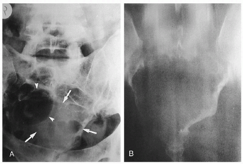
Xeroradiography has been used mainly for examination of the breast (mammography), though some applications in skeletal imaging have been found. (
Fig. 7-9) It is especially useful in the detection of foreign bodies and soft tissue problems.
Advantages.
The major advantage of the xeroradiography is the exquisite edge enhancement between different densities of bone and soft tissue, allowing far more detail than conventional films. (
11) For bone lesions, the procedure is useful in differentiating cartilaginous and osteogenic bone tumors as well as clearly demonstrating changes, such as calcification, in soft tissues. (
11)
Disadvantages.
Specific x-ray apparatus, cassettes, film, and processor are required. Of greatest concern are the high levels of radiation exposure required. The use of xeroradiography in contemporary skeletal imaging and mammography has been largely overtaken by other modalities.
Contrast Examinations
The major contrast examinations that may be used in the evaluation of skeletal disease are arthrography, angiography, lymphangiography, myelography, discography, and sinography.
Arthrography
Contrast opacification of joint cavities is a useful procedure in the evaluation of joint disease. Air is often combined with the injected
water-soluble media to provide a double-contrast arthrogram that provides better evaluation of the articular surfaces, menisci, and synovium. (
Fig. 7-10) The most common joint examined by this procedure is the knee. Other joints less frequently injected include the shoulder, hip, and wrist. In addition, tendon sheaths (tenography) and bursae (bursography) are examined by the same method. Injection into the spinal facet joints is often done before the injection of anti-inflammatory or analgesic agents. (
12)
Applications.
Clearly the major benefit of arthrography is in identifying intra-articular derangements of menisci or cartilage, ligamentous, and synovial abnormalities. Loose bodies, tears in cartilages, ligament tears, arthritic processes, and extension into adjacent tissues can all be clarified. MRI has reduced its usage.
Advantages.
Arthrography is a readily available technique that allows assessment of joint integrity and intra-articular components. Radiolucent structures such as cartilage are identifiable.
Disadvantages.
Drawbacks include the invasive nature of the procedure, operator and interpreter dependency, demonstration of only the surfaces of structures, and possible oversight of small lesions.
Angiography
The introduction of a water-soluble contrast agent into an artery (arteriogram) or vein (venogram) can add vital information to the understanding of the disease process and its subsequent management.
Applications.
Angiography is used mainly in the evaluation of bone tumors, vascular disease, traumatic musculoskeletal injuries, and avascular necrosis. In bone tumors, the size and aggressiveness of the lesion can be assessed by the degree of neovascularity, speed of media removal, and local structure invasion. Traumatic injuries may tear, distort, obstruct, dilate, or produce anomalous connections in vessels, which will be demonstrated only by angiography.
Advantages.
The isolation of arterial supply, the extent of the lesion, and its relationship to adjacent structures aid greatly in the surgical management.
Disadvantages.
Drawbacks to angiography include the requirement of specialized equipment in a specialized facility, the invasiveness of the procedure, potential complications (hematoma, infection, embolization), and relatively high radiation doses.
Lymphangiography
Evaluation of the lymphatic system can be achieved by the injection of an oil-based medium. Lymphangiography requires the injection of a blue-green dye between one or more webs of the toes, followed 1 hr later by an incision on the dorsum of the foot to identify a large lymphatic channel. Once identified, the channel is cannulated and an oil-based medium is injected slowly over 1-3 hr. Approximately 24 hr later, the contrast medium will be identifiable within the lower extremity, inguinal, iliac, and para-aortic nodes. The media may remain visible for many months.
Applications.
The major disorders evaluated with lymphangiography include lymphoma, metastasis, and lymphatic obstruction.
Advantages.
The lymph nodes and lymphatic channels are assessed according to location, size, shape, and configuration for evidence of abnormality. In addition, flow characteristics can be identified.
Disadvantages.
The main deterrents to the use of lymphangiography is the incision on the dorsum of the foot, length of time for the procedure, and the frequent difficulties in interpreting findings.
Myelography
Contrast examination of the spine and spinal cord is achieved by injection into the subarachnoid space, usually in the lumbar spine at the L2 or L3 level. The contrast media is a non-ionic water-soluble compound.
Applications.
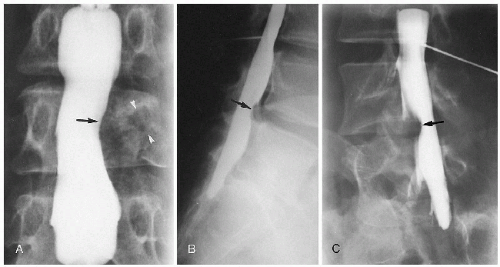
Myelography aids in the diagnosis of disc, vertebral canal, spinal cord, and nerve root disease. (
Fig. 7-11)
Advantages.
It is especially useful in determining multilevel spinal stenosis and injury at the junction of the nerve root and spinal cord.
Disadvantages.
This invasive procedure carries the risk of infection and iatrogenic complications, such as damage to nerve roots and dural tears. If bleeding occurs upon injection, the risk for arachnoiditis increases. Postmyelogram headache is encountered in about 40% of cases; those who experience headaches before myelography will develop a postmyelographic headache 60% of the time, whereas other patients will develop postmyelographic headache only 30% of the time. (
13) Anaphylaxis, while uncommon, can be a life-threatening complication. In view of these problems and limitations, MRI is considered the technique of choice in the investigation of the spinal cord and its surrounding intraspinal structures. (
14) A more complete discussion of myelography is offered in
Chapter 6.
Discography
Placement of water-soluble contrast media into the intervertebral disc under fluoroscopic control allows assessment of each disc injected.
Applications.
Injection of an opaque medium into the intervertebral nucleus pulposus (discography) has been used to evaluate discal pathology. Four aspects of the injected disc are assessed: the volume of contrast that can be injected (degenerative discs accept > 2 mL of contrast), the pain response of the patient on injection (provocational study), the pattern of contrast distribution (fissuring, extravasation, pooling), and the amount of resistance to injection. (
14)
Advantages.
Discography allows not only a morphologic analysis but also the functional aspect of pain provocation. The reproduction of symptoms on injection is interpreted as a positive isolating factor for identifying discogenic pain. (
15) When combined with CT (CT discography), the extent and orientation of internal annular tears (internal disc disruption) can be determined; such lesions are not routinely definable by any other means, including MRI. (
16)
Disadvantages.
Specialized equipment and a specialized facility are required to carry out discography. Use of fluoroscopy increases the radiation dose for the procedure. As an invasive procedure the usual risks for infection (0.1-0.2%), nerve root damage, dural trauma and tears, chemical meningitis, exacerbation or worsening pain, and allergic reactions do exist. The issue of whether discography can precipitate or accelerate disc degeneration is unclear at this stage, though most reports do not support the hypothesis that the procedure is a deleterious factor. (
17) A detailed discussion of this procedure is offered in
Chapter 6.
Sinography
Sinography is a selective technique applied in the evaluation of bone infections that are associated with a draining external sinus. The sinus is catheterized, and the contrast media is injected to show the origin and extent of the infection.
Radionuclide Imaging
The principle of nuclear imaging hinges on the selective uptake of certain compounds by different organs of the body. Tissues that can be imaged include the brain, heart, lung, kidneys, and skeleton. In bone imaging (bone scan) the most common isotope used is technetium-99m-methylene diphosphate (99mTc-MDP).
The procedure is performed by injecting 15-20 mCi of 99mTc intravenously and waiting various time periods—from 30 min to 2 hr—for concentration in bony areas of increased blood flow and osteoblastic activity. This is the typical triphasic (three-phase) study: an initial flow study, a slightly delayed blood pool study, and some hours later a delayed study. An imaging device—the γ-camera—is placed over the patient to record the bone-emitted γ-rays as the isotope undergoes decay to a lower energy level. These rays are filtered by a pinhole collimator and transformed into light, and an image is transposed onto a Polaroid or radiographic film.
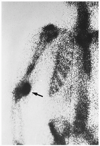
Projections of the entire body in the posteroanterior (PA) and anteroposterior (AP) planes are performed. In addition, selected spot projections over questionable locations are also obtained. Regions of increased uptake will show as dark spots (
hot spots). Normally the isotope will collect more in the long bone metaphyses, thyroid, bladder, kidneys, sternum, costochondral junctions, spine, sacroiliac joints, and at the injection site. (
18) (
Fig. 7-12) The isotope half-life is 6 hr and is readily excreted by the kidneys. The combination of tomography and isotopic bone scans (single-photon emission computed tomography, SPECT) allows accurate assessment of regions within bone or where bones overlap, such as the pars interarticularis in the lumbar spine.
Applications.
The indications for a bone scan include the detection of skeletal metastasis and other tumors, infection, arthritis, fracture, and avascular necrosis. This is especially useful in diagnosing occult, stress, and recent fractures; in addition it is used for patients whose plain films are normal but who have pain of undetermined origin. (
Fig. 7-13) Bone scans of the spine can be helpful in both the diagnosis and the therapeutic decision-making process, helping identify degeneration, pseudo-arthrosis in spinal fusions, active spondylolysis, spondylolisthesis, active fracture, infection, tumor, and metabolic disorders. It is not useful for evaluating spinal stenosis, disc herniation, or postlaminectomy status. (
19)
Advantages.
Only 3-5% bone destruction is necessary for pathologic bone destruction to be detected on a bone scan, representing up to 10 times more sensitivity than plain film radiography. Early, clinically unsuspected bone disease, such as metastasis, can be readily identified.
Disadvantages.
Diagnostically, the image obtained is quantitative only—it is a measure of activity. Therefore, the scan of a neoplasm may appear identical to one of an infection, with further correlation providing the definitive diagnosis. Some skeletal lesions remain inactive or show areas of no uptake on bone scans. This may occur in rapidly destructive processes and in multiple myeloma. A more complete discussion of radionuclide imaging is offered in
Chapter 6.
Ultrasound
Ultrasonography is frequently used in diagnosing abdominal, pelvic, and vascular disease. In problems of the musculoskeletal system, ultrasound is playing an increasingly greater role.
Applications.
Soft tissue masses—defining whether the mass is cystic or solid—cellulitis, abscess, and hematoma are amenable lesions for ultrasonographic investigation. Integrity of peripherally located tendons, especially the rotator cuff and Achilles tendon, can also be assessed. Neonatal and pediatric hip evaluation can be extremely rewarding in the early detection of congenital hip dysplasia, congenital hip dislocation, and intra-articular effusion. In the spine, ultrasound has limited use in the evaluation of spinal stenosis, disc herniation, and paraspinal soft tissue abnormalities. (
20,
21) Ultrasound provides a method of evaluating spondylolisthesis without the use of ionizing radiation. (
22)
Advantages.
Visualization of soft tissues adjacent to the peripheral articulations (e.g., shoulder, knee) is where ultrasound becomes increasingly useful. It can be rapidly performed, is non-invasive, does not involve ionizing radiation, and can provide a dynamic evaluation of the soft tissue. It can be useful in guiding biopsy or joint aspiration techniques. Another valuable application is the display of vascular integrity and flow velocity.
Disadvantages.
Although the periosteum is visualized, the medullary cavity of bone cannot be resolved on ultrasound. Similarly,
tissues close to bone may be obscured. Metal implants greatly inhibit detailed visualization of the adjacent soft tissues. The accuracy of the examination is extremely operator dependent and carries a long learning curve. (See
Chapter 6.)
Videofluoroscopy
Visualization of dynamic motion of body structures through fluoroscopy with recorded images has been a source of fascination for decades. Until the 1980s the method of recording was with 16- or 35-mm film and was referred to as
cineradiography. With the advent of videorecording the transcription process became greatly simplified. In the spine, motion patterns have been evaluated in normal and abnormal conditions, though the technique’s clinical efficacy has not been fully elucidated. (
5,
23) No consensus on normal standards of motion patterns exists, and a wide range of normal variations have been described.
Applications.
Motion of internal organs, passage of introduced contrast agents, and joint function have been the major outpatient applications of videofluoroscopy. Assessment of joint instability, such as at the atlantoaxial joint in the presence of odontoid anomalies, has been shown to be useful in preoperative evaluations. Effects of fusion (arthrodesis) on joint motion can be appreciated as can failure of the fusion procedure. Accurate assessment of joint function requires digitization. (
5,
23)
Advantages.
Dynamic characteristics of joint mechanics are visualized throughout the entire range of motion. Recording of the images allows the movement sequence to be slowed for frame-byframe analysis and digitization for accurate appraisal.
Disadvantages.
Radiation dose can be high if multiple planes are imaged. (
24,
25) The procedure itself is not lengthy, but the subsequent analysis requires considerable time. There is a paucity of literature on which to base meaningful estimations of motion magnitude and patterns. (
26) The expense and training necessary to do good fluoroscopic studies renders this modality most suited to the laboratory and not to routine clinical use. (
5,
23)
CT
The essential components of a CT system include a circular scanning gantry housing the x-ray tube and image sensors, a table for the patient, an x-ray generator, and a computerized data-processing unit. The patient lies on the table and is placed inside the gantry. The x-ray tube is rotated 360° around the patient while the computer collects the data and formulates a transverse image, or slice. Each cross-sectional slice represents a thickness of between 0.5 and 1.3 cm of body tissue. To produce an optimal examination, multiple sequential slices are obtained. In the lumbar spine 20-25 sequential slices produce an average total study dose of 1-3 rads. (
27) Contemporary computers are capable of producing multiplanar reconstructions (sagittal, coronal, oblique, and three-dimensional). (
28)
Applications.
Although CT has had its greatest impact in the evaluation of the central nervous system, various uses have been found in skeletal imaging. (
29) Following its introduction in 1973 by Hounsfield, many technical advances have occurred to improve resolution and diagnostic capability. (
30,
31) Skeletal applications include assessment of neoplasms, trauma, infections, metabolic disease, and spinal syndromes. (
29) (
Fig. 7-14) Bone mass determinations
for osteoporosis can be readily achieved (quantitative bone mineral analysis). The analysis of spinal syndromes is greatly improved when CT is combined with other modalities such as myelography (CT myelography), discography (CT discography), and angiography (CT-enhanced scan).
Advantages.
Exquisite depiction of bony and soft tissue anatomy is possible. Manipulation of the acquired data allows alterations in relative density (windows), measurements of density or distances (cursor), and display in multiple planes (multiplanar imaging).
Disadvantages.
Large patients and motion produce technically degraded images. Metal implants produce
star-shaped artifacts (blooming), and penetration of thick bones adjacent to lowattenuation soft tissues produces beam hardening. The averaging of densities throughout the thickness of the slice may result in inaccurate representation of tissue densities (volume averaging). The radiation dose can be relatively high and scanning times lengthy. (See
Chapter 6.)
MRI
MRI is also referred to as MR and nuclear magnetic resonance (NMR). The patient is placed in a magnetic field that displaces mobile hydrogen atoms, which can be measured and formed into an image. Those structures that have a high water content—such as the liver, spleen, muscles, and heart—produce the highest image details. The nucleus pulposus of the disc is readily identified in normal and degenerative conditions. When bone is examined, it is actually the marrow that forms the image, owing to the low levels of osseous water and high levels of fat.
Applications.
The use of MRI is widening rapidly. (
32) (
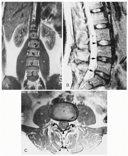
Fig. 7-15) Soft tissues are exquisitely captured and easily identifiable. Shoulder rotator cuff and Achilles tendon integrity are key areas of investigation. Because the bone marrow is imaged directly, MRI is extremely sensitive in detecting marrow disease. (
33) The internal architecture of the joints is seen with dramatic detail. In the spine, the structure and hydration of the disc are represented clearly, as are the cord, nerve roots, and intrinsic canal contents (such as the epidural fat, ligamentum flavum, and facet joints). (
34) (
Fig. 7-15, B and C) The use of intravenous contrast (gadolinium) shows areas of increased vascularity, including regions of neoplasm and inflammation.
Advantages.
Complications with MRI are few and can be avoided. Soft tissue contrast resolution is excellent; direct multiplanar imaging without reconstruction, use of non-ionizing radiation, and direct accurate characterization of pathologic tissue are its strengths.
Disadvantages.
Claustrophobia is a common problem because the patient is situated inside the noisy small tunnel for protracted times. The presence of some metallic clips, especially intracranially, may prevent use of MRI. Joint replacements are not a contraindication; however, pacemaker and cochlear implant patients should not be scanned. The expense of the study, availability, and extensive equipment and housing requirements do inhibit its use. (See
Chapter 6.)
