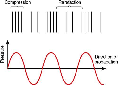
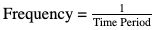
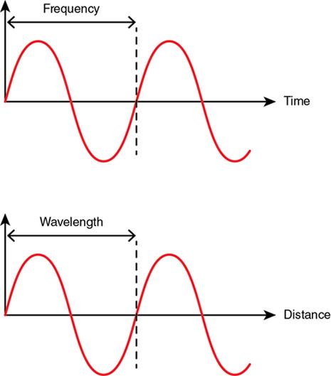
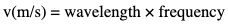
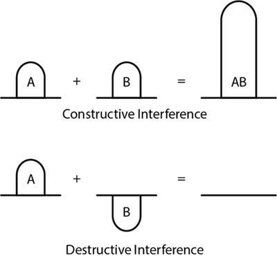
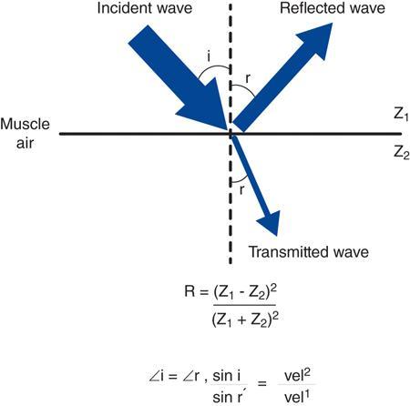
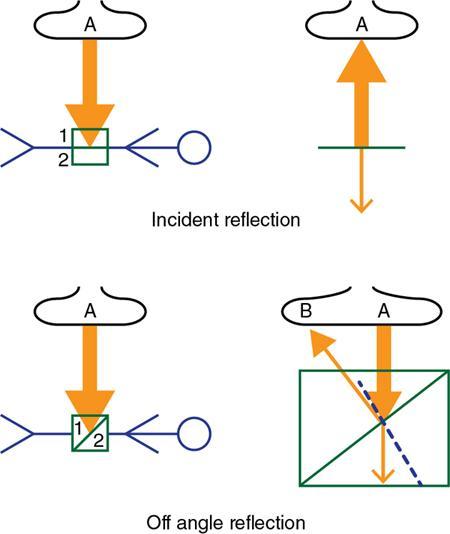
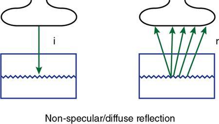
Shibani Mehra, Anshika Gulati A grand adventure is about to begin. Winnie the Pooh PRINCIPLES OF ULTRASONOGRAPHY A major breakthrough in medical imaging occurred with the discovery of the piezoelectric effect in 1880, which paved the way for use of sound waves to decipher anatomy of internal organs and distinguish normal from abnormal tissues enabling disease detection. Sound is a form of mechanical energy consisting of energy waves that have the ability to propagate in a medium. The propagation of sound occurs because the sound waves exert a force on the particles of the medium through which they traverse, pushing and compressing them together, creating oscillations. The standard terminology pertaining to sound is being discussed before we delve into the topic of ultrasound. The area within the medium where the sound waves cause the particles to get compressed together becomes a high-pressure compression zone, whereas the area where the particles of medium are spaced out becomes a low-pressure zone of rarefaction. A series of such compression and rarefaction zones within the medium set up particle vibrations, generating wave cycles, one wave cycle consisting of one compression and rarefaction zone together. Sound propagates in the form of longitudinal waves in fluid and gaseous media. In solids, however, it can travel either as longitudinal or transverse waves. The length of a wave is the distance between two successive compressions or rarefactions. Frequency of sound is defined as the number of wavelengths passing through the medium per second or the number of wavelength cycles occurring in 1 s. It denotes the number of times a particle of the medium oscillates when a sound wave exerts a force on it. The symbol of frequency is f and the SI unit is Hertz. Frequency = 1 Time Period A frequency of 1 Hz refers to one wave cycle per second, whereas sound of frequency 20 Hz is composed of 20 wave cycles per second, the waves cycles being 20 times shorter and closer together. Audible sound has a frequency between 20 and 20,000 cycles per second (hertz). The frequency of sound affects its amplitude. High-frequency waves have short wavelengths, carry less beam energy and, therefore, get more attenuated with increasing depth. This is defined as the distance of maximum displacement of a wave from its equilibrium position. In other words, amplitude is determined by the length of oscillation of particles of the conducting medium. Amplitude is responsible for the sound being audible. The larger the amplitude, the higher the intensity of sound. High-frequency waves produce a higher amplitude, i.e., more intense sound composed of more compact compression bands. The intensity of sound is measured in decibels. A decibel is 1/10th of a Bel, which is the unit to compare the relative intensities of two sound beams logarithmically using base 10. Decibels may have a positive or negative sign depending on whether there is gain or loss of power of the sound beam. The SI unit of intensity is watt/m2. It is defined as the rate at which sound travels in a medium. The speed of sound in a medium depends on two factors: The velocity of sound is inversely related to the compressibility of the conducting medium and also to the density of the material. Solids are less compressible; thus, sound travels faster in solids as the particles are packed close enough to be easily moved by the beam and produce waves. In gases, as also in air, the molecules are loosely arranged and far apart, making them more compressible; therefore, the velocity of sound is less in gases. Furthermore, the greater the density of the medium, the more massive its molecules, and the greater their inertia. Therefore, the velocity of sound has an inverse relationship to density as well: the more dense the material, the lesser the velocity of sound. See the velocity difference between fat and muscle? This is what makes you struggle so much while trying to examine an obese patient and still end up writing “suboptimal scan” due to patient body habitus! The relationship between wavelength, velocity and frequency is given by the formula: v (m/s) = wavelength × frequency Since the velocity of sound is constant in a particular medium, it is clear that the higher the frequency, the smaller the wavelength of the sound beam. Now let us introduce another concept which explains how the propagating sound waves interact with each other. When two waves that are “in phase” with each other come together so that their crests collide, they give rise to another wave of a higher amplitude. This phenomenon is known as constructive interference. When two sound waves that are “out of phase” with each other come together, the peak of one wave collides with the trough of the other, such that they tend to cancel each other out. This phenomenon is known as destructive interference. Ultrasound is sound with a frequency greater than 20,000 cycles per second (above 20 kHz); therefore, it is way beyond the audible range for the human ear. It is transmitted through a medium as a longitudinal sinusoidal wave due to the elastic forces that exist between the particles of the medium. In solids, during ultrasound propagation, transverse waves are also generated. However, most tissues in the body are regarded as fluids, except for bone. Thus, within the human body, ultrasound is propagated as longitudinal compression waves. Diagnostic ultrasound has a frequency range of 2–15 MHz (1Hz being one cycle per second). Frequency as high as 109 cycles per second can be generated by the current ultrasound scanners. Ultrasound beam loses energy as it traverses through body tissues; therefore, the returning beam is expressed in negative decibels. An ultrasonic wave undergoes three types of interactions, namely, reflection, refraction and absorption (or attenuation) when it travels through any material. In medical diagnostics, these three interactions take place when the ultrasound beam traverses the body tissues. Sound beam traversing through tissues within the body is reflected at the tissue interfaces. The percentage of the beam reflected depends on the following: The amount of beam reflected is inversely proportional to the angle of incidence; the closer the incident angle is to a right angle, the lesser the reflection. Angle of incidence (∠i) = Angle of reflection (∠r) (Snell’s law of Reflection). Critical angle is the angle of incidence at which the ultrasound beam is totally reflected from an interface. Snell’s law is applicable when the acoustic interface reflecting the beam has a smooth boundary. This type of reflection is known as specular reflection. Specular reflection is of two types: Incident reflection: When sound waves emitted from a point “A” of the transducer strike perpendicular to a tissue interface, a fraction of waves are reflected back as an echo towards the transducer and received by it at point “A” to form an image of the interface. Off-angle reflection: However, when the sound waves emitted from point “A” of the transducer are incident on the tissue interface at any angle, say ∆i, these waves are reflected by the same angle, say ∆r, and are received by the transducer at a different point “B”. It is this off-angle reflection of the incident ultrasound beam from various tissue interfaces that is primarily responsible for generation of the sonic image, which carries information about the tissue composition. At least 50% of the incident beam must be reflected to produce a desirable sonic image. The sum of the reflected and transmitted beam should be 100%. This too is of two types. If the angle at which the beam is incident on the reflecting surface is less than 90 degreees or if the wavelength of the incident beam equals that of the irregularities at the tissue interface or within the tissue, then the reflected beam is disorganized as it reflects; in other words, it scatters back. The backscatter too contributes to generation of a large proportion of the relevant portion of the image. Most of the solid organs in the body, namely, liver, spleen, kidney, uterine myometrium, etc. behave as nonspecular reflectors. Their parenchyma provides multiple tiny reflection interfaces of size smaller than wavelength of the incident sound beam, or sizes equal to the beam wavelength. Thus, the backscatter produced by nonspecular reflection is responsible for the “echotexture” of the abdominal and other body organs as presented on the ultrasound image. Not all nonspecular reflection is good though! When the wavelength of the incident beam is greater than the interface from which it is reflected, the entire beam, instead of getting reflected back in one direction, scatters in different directions. This is known as diffuse reflection or scattering, which is responsible for degrading the image quality. Diffuse scattering is independent of the angle of incidence. Acoustic impedance (Z) is a fundamental property of matter. It is defined as the product of the density of the medium and velocity of sound. It is measured in the unit “Rayl”. Z = ρ × c = density of medium × velocity of sound Since the velocity of sound is constant in a particular tissue, it is the density of the medium, which mainly determines the acoustic impedance. The amount of beam reflected is directly proportional to the difference in acoustic impedance at the tissue interface; the greater the difference in acoustic impedance, the greater the percentage of the beam reflected and the greater the diagnostic information obtained. R = ( Z1 − Z2 ) 2 ( Z1 + Z2 ) 2 where R is the fraction of sound reflected. This fact is important in imaging as near total beam reflection occurs at the air–soft tissue interface, due to a major difference in acoustic impedance of these two mediums. During an ultrasound examination, the acoustic gel applied between the skin and the probe acts as a coupling agent and works on the principle of impedance matching. It provides a low impedance interface between the probe and the skin surface and allows easy transmission of ultrasound waves to the internal tissues; else, the air pocket would have reflected the entire beam, owing to the large impedance difference of air and body tissues, hampering image formation. When the ultrasound beam travelling in a particular medium strikes the interface of another medium, there is a change in velocity of sound, and to accommodate this change, the wavelength of the beam also changes. The change in wavelength of the ultrasound beam brings about a change in beam direction, or refraction of the beam. The angle of refraction of ultrasound is determined by both, its angle of incidence and a ratio of velocity of beam in first and second mediums. sin i = vel 2 (Snell’s law of refraction). sin r′ vel 1 If the incident beam strikes perpendicular to the tissue interface (∠i = 0) or the speed of sound in both mediums is the same, there is no change in direction of propagation of the sound wave and no refraction occurs. The former situation hardly happens, but the latter does happen, i.e., speed of sound is not same at fluid–solid organ or air–solid organ interfaces in the body. Refraction is undesirable in diagnostic imaging. Refraction of the ultrasound beam leads to spatial distortion, image distortion and inferior image resolution. A proportion of the ultrasound beam is absorbed by the tissue in which it traverses and sound energy gets converted into heat energy. Absorption results in attenuation of the ultrasound beam. Excessive beam absorption is undesirable for good sonic image production, as the percentage of the beam reflected back becomes lesser. The amount of incident beam absorbed by a medium depends on the following: Frequency of the ultrasound beam affects the relaxation time of molecules. Relaxation time is the time taken by molecules of the medium to return to their original position after being displaced. The relaxation time increases with increase in frequency. Tissues with higher viscosity have greater internal friction, the frictional forces opposing the motion of particles in the medium. Absorption of the ultrasound beam is maximum in bone because of high viscosity and high relaxation time of compact bone tissue. The ultrasound image: As the ultrasound beam travels through the body, a percentage of the wave is reflected back to the transducer from tissue interfaces, while a percentage is transmitted deeper into the tissues, gets attenuated depending on the tissue viscosity, and the remainder travels back towards the transducer, after being reflected. The reflected beam is received by the transducer, and the sound beam carries information about body tissue composition. Sound energy is converted in the transducer into electrical signals, to get the desired information. The speed of sound in body tissues is 1540 m/second, and each echo returns in a millionth of a second. Transducers are the backbone of the ultrasound machine. They convert sound energy into electric energy and vice versa. The piezoelectric effect is the basis of ultrasound transducers. This effect states that application of an electric field causes a change in the physical dimension of certain materials. Transducers contain a piezoelectric crystal at their front end (the part that comes in contact with the patient’s body). Electrodes are plated to the front and back surface of this crystal. A thin conducting film covers the crystal to ensure good contact with the electrodes so that the electric signal, as well as the sound beam generated and subsequently received, is not lost. A backing block is placed against the inside electrode to absorb the sound waves that could be transmitted backwards. The piezoelectric crystal and electrode assembly are placed inside a housing made of resistant plastic. Placing cork or rubber inside the housing ensures that sound waves are not dissipated within the housing. On receiving the electrical signal from the electrodes, the transducer not only vibrates at its resonance frequency but also produces sound waves of frequency higher and lower than the resonance frequency. The backing block is incorporated in the transducer to quench these extra vibrations of the crystal, thereby to shorten the length of the sonic pulse. Tungsten and rubber powder are materials used for the backing block, mixed in an epoxy resin. Tungsten is chosen because its acoustic impedance is similar to that of the piezoelectric crystal. Rubber further increases the attenuation of sound. A piezoelectric material is made of an infinitely large number of dipoles, which are arranged in a geometric pattern. Dipoles are molecules carrying both a positive and a negative charge at either end. This is possible when first the piezoelectric crystal is heated to a high temperature in a strong electric field (to produce dipoles), and then gradually cooled. The purpose of gradual cooling is to fix the dipoles in the desired geometric alignment. Quartz is a natural piezoelectric substance. Medical ultrasound equipment uses ferroelectric substances such as barium titanate and lead zirconate, which are human-made. Lead zirconate titanate, which goes by the acronym PZT, is the substance used in most transducers. Curie temperature is the temperature which causes deactivation of the polarization within the piezoelectric crystal and renders it useless. Heating the crystal above this temperature brings about depolarization of the molecules, destroying the piezoelectric effect. Curie temperature for PZT crystals is around 660 F (350°C). Hence no autoclaving of ultrasound probes! The unique property of the transducer is that it is both a transmitter and a receiver. Since the same probe is the transmitter as well as the receiver of ultrasound waves, it is called a “transducer”. On receiving an electric signal, the crystal vibrates sending out ultrasound waves, and when these waves are reflected from the body tissues after hitting an interface, it vibrates again to produce an electric signal which is translated into an image. The transducer crystal is designed to vibrate in the thickness mode and not in the radial mode. A special circuit generates an oscillating voltage waveform for the electrodes of the piezoelectric crystal: the frequency of the voltage waveform is matched with the resonant frequency of the crystal. Transducers used in imaging are pulsed for two or three cycles with an average of 1000 pulses per second (range: 500–3000 pulses per second). Each point in the crystal produces multiple waves of short wavelengths that reinforce each other, and finally become continuous closer to the front surface of the transducer. The intensity of the ultrasound beam varies and is not constant along the entire length of the beam. Resonant frequency of the crystal is the natural frequency to which it is most maximally sensitive. A transducer is driven at its resonant frequency. The fundamental resonance frequency of the transducer is the frequency that corresponds to half of wavelength thickness. The thickness of the piezoelectric crystal determines a transducer’s resonant frequency. In other words, the thinner the crystal, the higher the fundamental frequency at which it will resonate. The piezoelectric crystal is extremely thin (its thickness is usually 0.5–1 mm). As the wavelength of sound is inversely proportional to the frequency, we derive here that thicker crystals produce lower-frequency ultrasound and thinner crystals emanate high-frequency waves. The thickness of the crystal is meant to be exactly half the wavelength of ultrasound to be produced by the transducer. So the only way to change the frequency of a transducer is to change the probe! It is the time interval between the beginning of vibrations, initiation of a sound wave and the dying down of vibrations completely. Since the transducer is both transmitter of ultrasound and receiver of electric impulses which are then converted to sound, it is important that the vibrations are initiated, die down quickly or have a low ring-down time so that the returning electric signal is not lost within the noise of the transducer. There are various types of transducers available depending on the body part to be imaged. Linear transducer: The piezoelectric crystals are arranged in a linear fashion, and the emanating ultrasound beam is rectangular. The frequency of these usually varies between 7.5 and 12 MHz. These are used for imaging superficial structures and vessels as the depth penetration of the beam is less. Convex transducer: The piezoelectric crystals are arranged in a curvilinear fashion producing a convex beam that has excellent depth penetration. This transducer has a wide footprint and frequency range between 2.5 and 7.5 MHz. These are mainly used for abdominal imaging. The arrangement of the piezoelectric crystals is such that they vibrate in phases. This is possible because of electronic steering of the beam and focussing. In a phased array transducer, if all crystal elements are fired simultaneously, the resultant ultrasound beam will completely travel forward in a straight direction. If, however, the elements are fired sequentially from right to left, or vice versa, then there will be constructive interference only in one direction, with destructive interference in all other directions. This is called electronic steering. This will steer the beam to the left or right. Phased array transducers have a small footprint and square shape and produce a narrow beam. The advantage is greater depth penetration. These are preferred for transcranial and cardiac imaging though they are also suitable for abdominal as well as transrectal and transvaginal imaging. Piezoelectric elements are arranged as concentric rings forming a circular layer. The advantage of this arrangement is improved spatial resolution, as the ultrasound beam can be focussed in both lateral and elevational planes (in detail later). The beam moves in a sweeping motion taking slices from different sides, which are assembled subsequently. Therefore, a three-dimensional or four-dimensional scanning is possible with these probes. Endocavity probes are specific for the body part to be examined. These probes have a longer handle and a U-shaped lens which provides a wider array so that they can be used inside the body. Their design depends on the part to be examined; thus, endorectal, endovaginal and transesophageal probes are available. These do not have a great depth range but provide a wide field of view. For a good quality image to be generated, the operator needs to know about the behaviour of the beam. This refers to the various controls available on the ultrasound machine. There are various presets available in the ultrasound machine, specific for each type of examination. The various knobs on the machine are as follows: A dropdown menu displays the different types of examinations possible. Presets are available for standard abdominal, obstetric, volume measurements, musculoskeletal, thyroid, scrotal breast or vascular imaging. Transducer selection: This feature allows selection of the transducer type, based on the desired examination. There are ports in the machine for attachment of different types of transducers, and selection of either a linear or curvilinear probe is possible. Registration of patient data with editing option. This function on the ultrasound console controls the pulse emitted from the probe. Ultrasound pulses with higher transmit power will return stronger echoes, producing a better signal, and forming a brighter image. Furthermore, high-amplitude pulses will penetrate to a greater depth. However, the downside of increasing the transmit power is that it widens the ultrasound beam, thereby decreasing the lateral resolution. Another disadvantage of increasing the transmit power is the possibility of potential bioeffects to the fetus, especially in the first-trimester scan, from increased ultrasound exposure, which theory is yet to be proved. This knob determines the potential difference across the transducer, which in turn is responsible for the strength of the voltage pulse that generates the ultrasound beam for imaging. Increasing the intensity increases the overall quality of the sound beam produced by the transducer with stronger amplitude echoes at all levels. Just like that transmit power, the gain knob on the ultrasound console adjusts the overall brightness of the image by amplifying the returning echoes. The gain adjustment has no effect on signal-to-noise ratio or depth of beam penetration. It brightens or darkens the entire image regardless of depth of reflectors. The difference between the transmit power knob and gain knob is that the former adjusts the image brightness by strengthening the transmitted pulse, while the 2D gain knob improves brightness by amplifying the returning echoes. The TGC knob or time gain compensation knob allows adjustment of image brightness at specific depths. The top row of buttons controls the near-field gain, while the bottom row buttons control the far-field gain. Increasing the gain leads to a brighter image but also increases the image noise and artefact, with loss of both contrast and fine details. Reducing the overall gain makes the image darker. The depth knob: This knob adjusts the penetration of the ultrasound beam, a scale on the left or the right of the monitor screen displaying the depth. Beam penetration increases in 0.5–1 cm increments. Scanning of thicker and deeper organs requires increased depth penetration. The disadvantage of scanning at increased depth, however, is a reduction in frame rate, which compromises the image quality. The zoom knob: It magnifies either the entire image or merely the area of interest. Dynamic range refers to the ratio of highest to lowest amplitudes that are received by the transducer. It is measured in dB and is analogous to window width in CT. A larger dynamic range provides a lower contrast gradient on the image display; however, the image appears smoother. A smaller dynamic range, on the other hand, gives better contrast with the downside being a coarser image. The Focus knob moves the focal point between the near and far zones and brings the narrowest part of the beam into play. Focused transducers improve the lateral resolution by restricting the beam width. The thickness of tissue imaged depends on the focusing range of the transducer. The focal length of a transducer can be gauged by the diameter of curvature of the lens. Focus can be adjusted according to the depth of interest. The Freeze button freezes and saves an image of the organ being examined. The Caliper knob is used to measure the size of organs or the size of mass lesions. The Select key is used to toggle between two calipers. The Cine button documents the last few frames as a short video clip. Artefacts are produced because of the violation of the assumptions or rules that are taught to the computer to make calculations and generate images. At the outset, it is important to know that not all artefacts are bad. Many of them contain diagnostic information and are known as friendly artefacts. Let us understand the artefacts by first understanding the assumptions or rules, violation of which produces artefacts. Assumption 1: It is assumed that a sound wave emitted from the probe undergoes a single reflection before returning to the probe. Assumption 2: It is assumed that the sound beam and its echo travel in a straight line. Assumption 3: Rule 3: It is assumed that both the sound beam and the echo travel in the human body at a fixed speed of 1540 m/s. The amount of time an echo takes to return to the transducer is a measure of the depth of the reflector. d = vt 2
1.8: Principles of ultrasound and doppler
Introduction to sound
Wave cycle
Propagation of sound
Wavelength
Frequency
Amplitude
Velocity of sound
Velocity of sound in different materials
Propagation Medium
Velocity of Sound (m/s)
Air
330
Fat
1450
Water
1480
Soft tissues (average)
1540
Muscle
1580
Bone
4080
Does the wavelength of sound change depending on the composition of the medium?
Interference
What is ultrasound?
Interactions of ultrasound with matter
Reflection
Nonspecular reflection (scattering)


Impedance matching
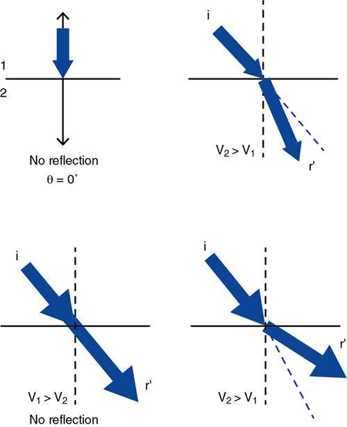
Refraction
Absorption
Ultrasound methods
Equipment
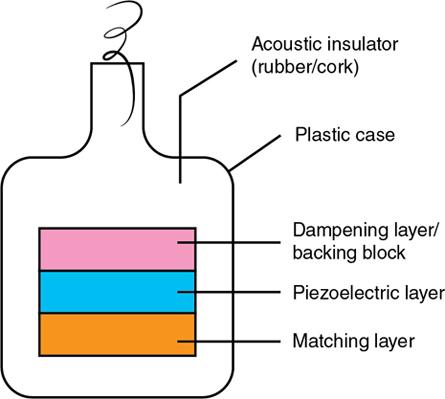
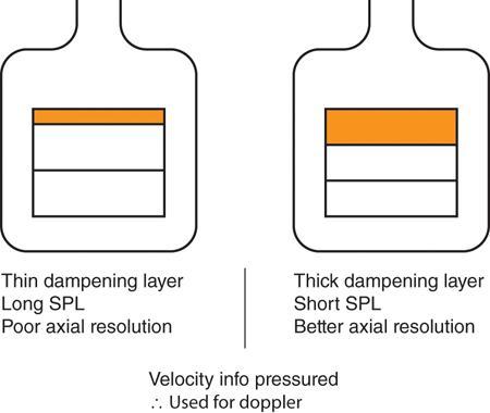
Importance of a backing block
What is a piezoelectric crystal?
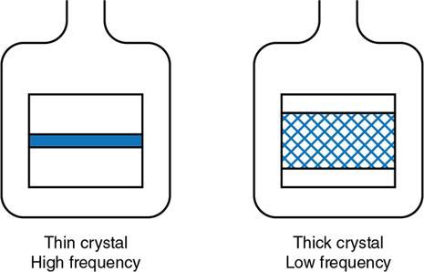
Generation of ultrasound by the transducer
Ring-down time of transducer
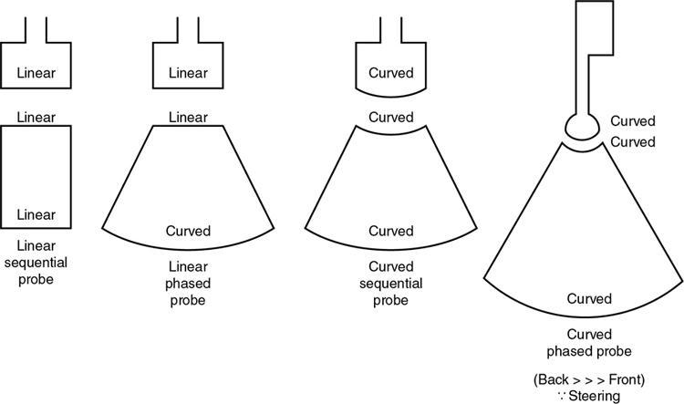
Types of transducers
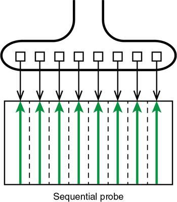
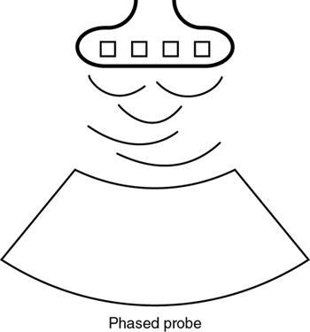
Phased array transducers
Annular array transducers
Knobology
Transmit power
Intensity control
2D gain
The dynamic range knob
Ultrasound artefacts

Related posts:
![]()
Stay updated, free articles. Join our Telegram channel

Full access? Get Clinical Tree


Principles of ultrasound and doppler
1.8.1