Production of X-rays
X-rays were discovered by Roentgen in 1895 while studying cathode rays (stream of electrons) in a gas discharge tube. He observed that another type of radiation was produced (presumably by the interaction of electrons with the glass walls of the tube) that could be detected outside the tube. This radiation could penetrate opaque substances, produce fluorescence, blacken a photographic plate, and ionize a gas. He named the new radiation x-rays.
Following this historic discovery, the nature of x-rays was extensively studied and many other properties were unraveled. Our understanding of their nature was greatly enhanced when they were classified as one form of electromagnetic radiation (section 1.10).
3.1. The X-Ray Tube
Figure 3.1 is a schematic representation of a conventional x-ray tube. The tube consists of a glass envelope that has been evacuated to high vacuum. At one end is a cathode (negative electrode) and at the other an anode (positive electrode), both hermetically sealed in the tube. The cathode is a tungsten filament that when heated emits electrons, a phenomenon known as thermionic emission. The anode consists of a thick copper rod at the end of which is placed a small piece of tungsten target. When a high voltage is applied between the anode and the cathode, the electrons emitted from the filament are accelerated toward the anode and achieve high velocities before striking the target. The x-rays are produced by the sudden deflection or acceleration of the electron caused by the attractive force of the tungsten nucleus. The physics of x-ray production will be discussed later, in section 3.4. The x-ray beam emerges through a thin glass window in the tube envelope. In some tubes, thin beryllium windows are used to reduce inherent filtration of the x-ray beam.
A. The Anode
The choice of tungsten as the target material in conventional x-ray tubes is based on the criteria that the target must have high atomic number and high melting point. As will be discussed in section 3.4, the efficiency of x-ray production depends on the atomic number, and for that reason, tungsten with Z = 74 is a good target material. In addition, tungsten, which has a melting point of 3,370°C, is the element of choice for withstanding intense heat produced in the target by the electronic bombardment.
Efficient removal of heat from the target is an important requirement for the anode design. This has been achieved in some tubes by conduction of heat through a thick copper anode to the outside of the tube where it is cooled by oil, water, or air. Rotating anodes have also been used in diagnostic x-rays to reduce the temperature of the target at any one spot. The heat generated in the rotating anode is radiated to the oil reservoir surrounding the tube. It should be mentioned that the function of the oil bath surrounding an x-ray tube is to insulate the tube housing from high voltage applied to the tube as well as absorb heat from the anode.
Some stationary anodes are hooded by a copper and tungsten shield to prevent stray electrons from striking the walls or other nontarget components of the tube. These are secondary electrons produced from the target when it is being bombarded by the primary electron beam. Whereas copper in the hood absorbs the secondary electrons, the tungsten shield surrounding the copper shield absorbs the unwanted x-rays produced in the copper.
An important requirement of the anode design is the optimum size of the target area from which the x-rays are emitted. This area, which is called the focal spot, should be as small as possible
for producing sharp radiographic images. However, smaller focal spots generate more heat per unit area of target and, therefore, limit currents and exposure. In therapy tubes, relatively larger focal spots are acceptable since the radiographic image quality is not the overriding concern.
for producing sharp radiographic images. However, smaller focal spots generate more heat per unit area of target and, therefore, limit currents and exposure. In therapy tubes, relatively larger focal spots are acceptable since the radiographic image quality is not the overriding concern.
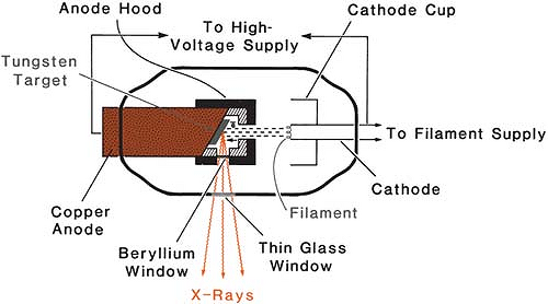 Figure 3.1. Schematic diagram of a therapy x-ray tube with hooded anode. |
The apparent size of the focal spot can be reduced by the principle of line focus, illustrated in Figure 3.2. The target is mounted on a steeply inclined surface of the anode. The apparent side α is equal to A sin u, where A is the side of the actual focal spot at an angle u with respect to the perpendicular to the electron beam direction. Since the other side of the actual focal spot is perpendicular to the electron, its apparent length remains the same as the original. The dimensions of the actual focal spot are chosen so that the apparent focal spot results in an approximate square. Therefore, by making the target angle u small, side α can be reduced to a desired size. In diagnostic radiology, the target angles are quite small (6–17 degrees) to produce apparent focal spot sizes ranging from 0.1 × 0.1 mm to 2 × 2 mm. In most therapy tubes, however, the target angle is larger (about 30 degrees) and the apparent focal spot ranges between 5 × 5 mm and 7 × 7 mm.
Since the x-rays are produced at various depths in the target, they suffer varying amounts of attenuation in the target. There is greater attenuation for x-rays coming from greater depths than those from near the surface of the target. Consequently, the intensity of the x-ray beam decreases from the cathode to the anode direction of the beam. This variation across the x-ray beam is called the heel effect. The effect is particularly pronounced in diagnostic tubes because of the low x-ray energy and steep target angles. The problem can be minimized by using a compensating filter to provide differential attenuation across the beam in order to compensate for the heel effect and improve the uniformity of the beam.
B. The Cathode
The cathode assembly in a modern x-ray tube (Coolidge tube) consists of a wire filament, a circuit to provide filament current, and a negatively charged focusing cup. The function of the cathode cup is to direct the electrons toward the anode so that they strike the target in a well-defined area, the focal spot. Since the size of the focal spot depends on filament size, the diagnostic tubes usually
have two separate filaments to provide “dual focus,” namely one small and one large focal spot. The material of the filament is tungsten, which is chosen because of its high melting point.
have two separate filaments to provide “dual focus,” namely one small and one large focal spot. The material of the filament is tungsten, which is chosen because of its high melting point.
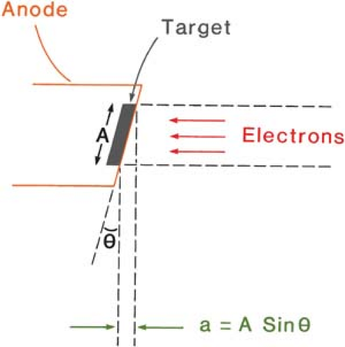 Figure 3.2. Diagram illustrating the principle of line focus. The side A of the actual focal spot is reduced to side α of the apparent focal spot. The other dimension (perpendicular to the plane of the paper) of the focal spot remains unchanged. |
3.2. Basic X-Ray Circuit
The actual circuit of a modern x-ray machine is very complex. In this section, however, we will consider only the basic aspects of the x-ray circuit. For more detailed information the reader is referred to the literature.
A simplified diagram of a self-rectified therapy unit is shown in Figure 3.3. The circuit can be divided into two parts: the high-voltage circuit to provide the accelerating potential for the electrons and the low-voltage circuit to supply heating current to the filament. Since the voltage applied between the cathode and the anode is high enough to accelerate all the electrons across to the target, the filament temperature or filament current controls the tube current (the current in the circuit due to the flow of electrons across the tube) and hence the x-ray intensity.
The filament supply for electron emission usually consists of 10 V at about 6 A. As shown in Figure 3.3, this can be accomplished by using a step-down transformer in the alternating current line voltage. The filament current can be adjusted by varying the voltage applied to the filament. Since a small change in this voltage or filament current produces a large change in electron emission or the current (see Fig. 3.10), a special kind of transformer is used that eliminates normal variations in line voltage.
The high voltage to the x-ray tube is supplied by the step-up transformer (Fig. 3.3). The primary of this transformer is connected to an autotransformer and a rheostat. The function of the autotransformer is to provide a stepwise adjustment in voltage. The device consists of a coil of wire wound on an iron core and operates on the principle of inductance. When an alternating line voltage is applied to the coil, potential is divided between the turns of the coil. By using a selector switch, a contact can be made to any turn, thus varying the output voltage that is measured between the first turn of the coil and the selector contact.
The rheostat is a variable resister (i.e., a coil of wire wound on some cylindrical object with a sliding contact to introduce as much resistance in the circuit as desired and thus vary the voltage in a continuous manner). It may be mentioned that, whereas there is appreciable power loss in the rheostat because of the resistance of the wires, the power loss is small in the case of the inductance coil since the wires have low resistance.
The voltage input to the high-tension transformer or the x-ray transformer can be read on a voltmeter in the primary part of its circuit. The voltmeter, however, is calibrated so that its reading corresponds to the kilovoltage that will be generated by the x-ray transformer secondary coil in the output part of the circuit and applied to the x-ray tube. The tube voltage can be measured by the sphere gap method in which the voltage is applied to two metallic spheres separated by an air gap. The spheres are slowly brought together until a spark appears. There is a mathematical relationship between the voltage, the diameter of the spheres, and the distance between them at the instant that the spark first appears.
The tube current can be read on a milliammeter in the high-voltage part of the tube circuit. The meter is actually placed at the midpoint of the x-ray transformer secondary coil, which is grounded. The meter, therefore, can be safely placed at the operator’s console.
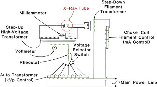 Figure 3.3. Simplified circuit diagram of a self-rectified x-ray unit. |
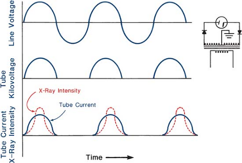 Figure 3.4. Graphs illustrating the variation with time of the line voltage, the tube kilovoltage, the tube current, and the x-ray intensity for self- or half-wave rectification. The half-wave rectifier circuit is shown on the right. Rectifier indicates the direction of conventional current (opposite to the flow of electrons). |
The alternating voltage applied to the x-ray tube is characterized by the peak voltage and the frequency. For example, if the line voltage is 220 V at 60 cycles/sec, the peak voltage will be √2 = 311 V since the line voltage is normally expressed as the root mean square value. Thus, if this voltage is stepped up by an x-ray transformer of turn ratio 500:1, the resultant peak voltage applied to the x-ray tube will be √2 × 500 = 155,564 V = 155.6 kV.
Since the anode is positive with respect to the cathode only through half the voltage cycle, the tube current flows through that half of the cycle. During the next half-cycle, the voltage is reversed and the current cannot flow in the reverse direction. Thus, the tube current as well as the x-rays will be generated only during the half-cycle when the anode is positive. A machine operating in this manner is called the self-rectified unit. The variation with time of the voltage, tube current, and x-ray intensity1 is illustrated in Figure 3.4.
Related posts:

Stay updated, free articles. Join our Telegram channel

Full access? Get Clinical Tree


