Pulse Sequence Diagram
“A pulse sequence diagram is to an MR scientist as sheet music is to a musician.”
Introduction
A pulse sequence diagram (PSD) illustrates the sequence of events that occur during magnetic resonance imaging (MRI). It is a timing diagram showing the radio frequency (RF) pulses, gradients, and echoes. Having a good knowledge of the PSD will help the reader follow complicated pulse sequences with more ease and understand the interplay among various scan parameters.
PSD of an SE Sequence
Having been exposed to the concept of gradients, we are now able to illustrate a complete PSD for, say, a spin-echo (SE) sequence (Fig. 14-1). Everything in the figure looks like what we have discussed before except for a few adjustments in
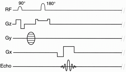 Figure 14-1. A spin-echo PSD. |
1. Slice-select gradient (Gz)
2. Frequency-encoding gradient (Gx)
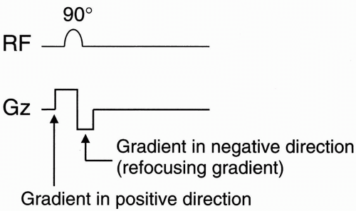
1a. Once the slice-select gradient (Gz) is applied, then a gradient in the negative direction is introduced in order to refocus the spins (Fig. 14-2). Basically, every time we apply a gradient, we dephase the spins. In the case of the Gz gradient, we dephase the spins in order to select a slice. But after the slice is selected, we need to reverse the effect. The purpose of the refocusing gradient is to rephase the spins in the slice-select direction. (Alternatively, we can defocus the spins prior to slice selection so that
they come back into phase with the second gradient pulse.)
they come back into phase with the second gradient pulse.)
1b. When the 180° pulse is applied, a sliceselect gradient may or may not be applied. This is optional and depends on whether a single slice or multiple slices are being acquired. But before and after the 180° pulse, we apply a socalled crusher gradient so that the 180° pulse has a tri-lobed shape (Fig. 14-3). This is just a triviality. When the 180° pulse is applied, it may have elements that are not exactly 180° leading to unwanted additional transverse magnetization. This may result in the echo not focusing at time TE, as we would expect. So these “crusher” gradients are applied to offset that error. (The first lobe is used to balance the third; the second is slice selective; the third destroys the free induction decay [FID] from the unwanted transverse magnetization.)
2. There is an important adjustment in the readout gradient (Gx). If we just apply a gradient while we’re reading out the echo, we end up dephasing everything (Fig. 14-4). By the time we get to the middle of the signal, the signal intensity will be decreased because of the dephasing caused by the gradient, and by the time we get to the end of the signal, there will be maximum dephasing and so much signal loss that there may not be any signal to read!
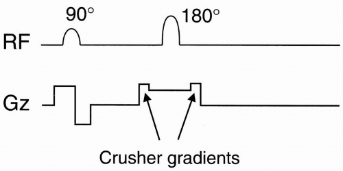 Figure 14-3. Crusher gradients are applied at each side of the slice-selective gradient (applied during the 180° pulse) to achieve more accurate refocusing at time TE. |
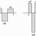
So we apply a gradient in the negative direction that has an area equal to ½ of that of the readout gradient (Fig. 14-5). The length of the readout gradient is the sampling time (Ts). For stationary spins, application of a gradient will make the spins go faster and faster and, as they go faster, they’ll get out of phase. With the negative gradient, the stationary spins will have a maximum phase difference at the end of the negative gradient. As the gradient is reversed and a gradient in the positive direction is applied, the spins will rephase once again. This occurs right at the midpoint of the readout, that is, at time TE. Subsequently, they’ll go out of phase again. We can see that at time TE everything is refocused (Fig. 14-5).
If we didn’t have the negative gradient lobe, the spins would begin to dephase when the gradient is turned on, and at time TE there would be an undesirable phase difference. Phase difference means a smaller signal (Fig. 14-6).
Sometimes, we’ll see the notation for the extra Gx gradient illustrated differently (Fig. 14-7


Stay updated, free articles. Join our Telegram channel

Full access? Get Clinical Tree


