Quality Assurance
The term quality assurance (QA) describes a program that is designed to control and maintain the standard of quality set for that program. For radiation oncology, a quality assurance program is essentially a set of policies and procedures to maintain the quality of patient care. The general criteria or standards of quality are usually set collectively by the profession. It is expected that a QA program designed specifically for an institution will meet those standards.
Model QA programs in radiation oncology have been proposed by professional organizations such as the American College of Radiology (ACR) (1), the American Association of Physicists in Medicine (AAPM) (2), and the American College of Medical Physics (ACMP) (3). These programs incorporate many of the standards and criteria developed by the National Council on Radiation Protection and Measurements (NCRP), the International Commission on Radiation Units and Measurements (ICRU), the International Commission on Radiological Protection (ICRP), and the International Electrotechnical Commission (IEC). In addition, mandatory programs with QA components have been instituted by the Nuclear Regulatory Commission (NRC) and the individual states. The Joint Commission has also set minimum standards of QA that are required of hospitals seeking accreditation.
Despite the many standard-setting bodies and the regulatory agencies, the standards of radiation oncology practice are quite varied across the United States. A patterns of care study (4), using Hodgkin’s disease, prostate cancer, and cervix cancer as examples, showed correlations between patient outcome and facility equipment, structure, technical support, and physician characteristics. These data underscore the importance of quality assurance in providing patients the best chance for cure.
The major reason for the lack of commitment to QA by many institutions is financial. An adequate QA program requires increased staffing and up-to-date equipment, both of which can be expensive. According to the analysis by Peters (5), the total cost of the QA program in radiation therapy amounts to approximately 3% of the annual billing for combined technical and professional charges. Because QA programs are voluntary (with the exception of the NRC or the state-mandated component), the only incentive to establishing these programs is a desire to practice good radiation therapy or avoid malpractice suits. However, the latter has not been a sufficient deterrent to effect change.
17.1. Goals
The Inter-Society Council for Radiation Oncology specifies the goals of a QA program in what is called the Blue Book (6):
The purpose of a Quality Assurance Program is the objective, systematic monitoring of the quality and appropriateness of patient care. Such a program is essential for all activities in Radiation Oncology. The Quality Assurance Program should be related to structure, process and outcome, all of which can be measured. Structure includes the staff, equipment and facility. Process covers the pre- and post-treatment evaluations and the actual treatment application. Outcome is documented by the frequency of accomplishing stated objectives, usually tumor control, and by the frequency and seriousness of treatment-induced sequelae.
That “such a program is essential for all activities in radiation oncology” emphasizes the need for a comprehensive QA program that includes administrative, clinical, physical, and technical aspects of radiation oncology. Operationally, no single personnel has the expertise to cover all these areas. Therefore, teamwork is essential among administrators, radiation oncologists, nurses, medical
physicists, and therapy technologists. For a QA program to be effective, all the staff involved with the radiation oncology service must be well coordinated and committed to QA.
physicists, and therapy technologists. For a QA program to be effective, all the staff involved with the radiation oncology service must be well coordinated and committed to QA.
The American College of Radiology has recommended that a quality assurance committee (QAC) be formed with appropriate personnel (e.g., radiation oncologist, physicist, dosimetrist, therapist, nurse, and administrator) to represent the various aspects of radiation oncology (7). This committee will meet on a regular basis to review the QA program and oversee its implementation. If there were a hospital-wide QA program, the radiation oncology QAC would coordinate its activities with the hospital QAC.
The multidisciplinary nature of a radiation oncology QA program precludes a comprehensive coverage of the subject in this book. Only the physical aspects of radiation oncology QA will be presented here. For further details, the reader is referred to reports generated by the various organizations (1,2,3,8).
17.2. Physics Staffing
The physics component of quality assurance in radiation oncology is one of the major responsibilities of the radiation physicist. Adequate physics staffing, in proportion to patient load and equipment, is required to carry out these responsibilities properly. The Blue Book recommends at least one physicist per center for up to 400 patients treated annually (Table 17.1). Additional physicists are recommended in the ratio of 1 per 400 patients treated annually. These recommendations are for clinical service only. They do not include staffing for research, teaching, or administrative functions.
Additional personnel will be required for QA of modern imaging equipment mounted on accelerators (e.g., cone-beam computed tomography [CT] system, electronic portal imaging device
[EPID]), CT simulators, and positron emission tomography (PET)/CT. Staffing levels must also take into account the sophistication and complexity of treatments offered (e.g., intensity-modulated radiation therapy [IMRT], image-guided radiation therapy [IGRT], high-dose-rate [HDR] brachytherapy, prostate implants, stereotactic radiosurgery, tomotherapy, proton therapy). These technologies and treatment methodologies were not available when the Blue Book guidelines were published in 1991.
[EPID]), CT simulators, and positron emission tomography (PET)/CT. Staffing levels must also take into account the sophistication and complexity of treatments offered (e.g., intensity-modulated radiation therapy [IMRT], image-guided radiation therapy [IGRT], high-dose-rate [HDR] brachytherapy, prostate implants, stereotactic radiosurgery, tomotherapy, proton therapy). These technologies and treatment methodologies were not available when the Blue Book guidelines were published in 1991.
Table 17.1 Minimuma Personnel Requirements for Clinical Radiation Therapy | ||||||||||||||||||||||||||||||||||||||
|---|---|---|---|---|---|---|---|---|---|---|---|---|---|---|---|---|---|---|---|---|---|---|---|---|---|---|---|---|---|---|---|---|---|---|---|---|---|---|
| ||||||||||||||||||||||||||||||||||||||
 Figure 17.1. Patterns of interaction among treatment-planning personnel. A: Radiation oncologist works alone. B: Radiation oncologist and dosimetrists generate a treatment plan. C: Teamwork between radiation oncologist, physicist, and dosimetrist. |
Many of the clinical physics tasks that have been traditionally performed by physicists can be delegated to dosimetrists or physics assistants. For example, dosimetrists can assist in routine QA checks, computer treatment planning, and monitoring unit calculations and brachytherapy source preparations. A physicist in this case has a role in establishing the procedures, directing the activities, and reviewing the results.
In treatment planning, Figure 17.1 illustrates how physics support is usually organized in this country. Arrangement A, in which the physician practically works alone or does not seek consultation from the physics team, is obviously not appropriate and is contrary to the concept of a multidisciplinary approach to radiation oncology. Arrangement β is not satisfactory either but is prevalent in many institutions. There may be several reasons why an essential member of the team, the physicist, is excluded in this case from the clinical process. Economics is one reason, as physicists are usually higher salaried than the dosimetrists. Other reasons may include having physicists who lack clinical training or a well-defined role in the clinic. Nonetheless, arrangement C is probably the best approach, as it involves teamwork among personnel whose responsibilities are matched with their credentials.
The Blue Book recommendation on dosimetrist staffing is 1 per 300 patients treated annually. In some institutions, dosimetrists perform physics work only, whereas in others they also do simulations. The relative proportion of a dosimetrist’s efforts to various tasks is dictated by the individual needs of the department, the scope of the physics activities, and the extent of other physics and technical support available.
A. Training
Besides the adequacy of physics staffing in terms of number of personnel in relation to the patient load or equipment, education and training of these personnel are of critical importance. The greatest weakness in this regard has been the physicist’s training. Most physicists are hired with less than adequate clinical training. Structured clinical training programs have been traditionally nonexistent. Certification boards for physicists exist, but the entry requirements for the examination still do not mandate residency-type clinical training as is required of the physicians. As a result, there is an unchecked influx of inadequately trained physicists into the field.
The physicist’s training problems are being addressed at the national level (9,10,11). Physics residency programs are being instituted, although at a much slower pace than needed. It is hoped that eventually all clinical medical physicists will be required to go through nationally accredited residency programs before taking the board examinations or assuming independent clinical responsibilities. Recently, the American Board of Radiology (http://www.theabr.org)—the certifying board for radiological physicists—has decided that “Beginning in 2014… candidates must be enrolled in or have completed a CAMPEP [Commission on Accreditation of Medical Physics Educational Programs] accredited residency program.”
Just as formalized clinical training is important for physicians and physicists, it is also important for dosimetrists. The American Association of Medical Dosimetrists has formalized the training of dosimetrists by establishing training curricula, accreditation, and professional certification.
B. Qualifications
Qualifications of a clinical medical physicist have been debated in the past, but recently a consensus has developed among the various national organizations. A radiation oncology physicist is considered qualified if he or she has an M.S. or Ph.D. degree in physics, medical physics, or a closely related field and a certification in radiation oncology physics by the American Board of Radiology, the American Board of Medical Physics, or another appropriate certifying body.
A qualified medical dosimetrist has a minimum of a high school diploma and a certification by the American Association of Medical Dosimetrists. Most certified dosimetrists also are certified radiation therapy technologists.
C. Roles and Responsibilities
The roles and responsibilities of the physics team have been discussed in the literature (11,12,13) and are summarized in Table 17.2. As emphasized previously, the physicist must direct the physics team and assume full responsibility of the physics data and procedures applied to the patients, irrespective of whether these activities are carried out by the physicist, dosimetrist, or other personnel. This unambiguous responsibility of physics procedures by the physicist is based on the same rationale as the physician’s control of medical prescription. Nonconformity to this principle can pose a serious risk to the patient.
The radiation oncologist undoubtedly has the overall responsibility for the conduct of the entire treatment process. Because of that role, it is his or her responsibility to ensure that an adequate and competent physics team is in place and that the roles of different personnel on the team are appropriately defined. It has been recognized that inadequacy of physics support translates into substandard or less than optimal patient care (4,6).
Calibration of radiation generators or sources is the exclusive responsibility of the medical physicist. No other personnel has the expertise to perform this most critical function. Because of the absolute necessity of the calibration procedure before the machine can be released for patient treatment, all institutions manage to acquire physics support at least sufficient to provide periodic calibration of the radiation equipment. However, these periodic calibrations, outside of a well-structured quality assurance program, are inadequate and cannot ensure continued safety of machine operation on a daily basis (14).
Next to calibration and quality assurance of radiation equipment is the physicist’s role in treatment planning. Although the treatment-planning process involves sophisticated physics concepts in designing and optimizing patient treatments, most institutions do not involve physicists sufficiently in this process. As discussed previously (Fig. 17.1), some physicians tend to work alone or with dosimetrists to design treatment plans. It should be realized that the absence of a physicist from the treatment-planning scene takes away an important element of quality control, namely the optimization and scientific authentication of the treatment plan. The physicist’s direct involvement in the treatment-planning process is possible only if the consultation is sought by the radiation oncologist. If the latter is not accustomed, by training or experience, to such interactions, the physicist is not brought into the treatment-planning loop. Consequently, an important member of the treatment-planning team is bypassed.
Table 17.2 Roles and Responsibilities of Physicists | |||||||||||||||||||||||||||||||||||
|---|---|---|---|---|---|---|---|---|---|---|---|---|---|---|---|---|---|---|---|---|---|---|---|---|---|---|---|---|---|---|---|---|---|---|---|
| |||||||||||||||||||||||||||||||||||
At some institutions, the physicist’s role in treatment planning has been made indispensable. For example, at the University of Minnesota the physicist’s consultation is made as important as other consultations, such as those sought from the medical oncologist, the surgeon, or the radiologist. To prevent bypassing the physics consultation, each patient is assigned a physicist who is available at the time of simulation to assist the radiation oncologist in formulating the best possible treatment plan. Subsequent physics work is the designated physicist’s responsibility, although he or she may be assisted by the dosimetrist or other technical personnel. The final treatment plan is approved by the radiation oncologist after discussing the plan with the physicist. Also, the physicist is present at the time of first treatment and subsequent treatments, if needed, to ensure proper implementation of the plan.
Not all the clinical physics procedures need to be performed by physicists. Many of the technical tasks can be delegated to dosimetrists so that physicists can devote time to essential developmental activities. Every radiation oncology department needs to develop new programs as well as revise the old ones to keep current with advancements in the field. Responsibility often rests with the physicist to implement these advances while maintaining the quality of care. Examples from the past three decades include development of linear accelerator technology, computer imaging, 3-D treatment planning, conformal and dynamic therapy, and remote afterloading brachytherapy. Whereas these technologies were not developed exclusively by physicists, they had an important role in their design and clinical application. Along with these major advancements came the innovations in treatment techniques, for example, mantle fields, total body irradiation, electron beam therapy, intensity-modulated radiation therapy, stereotactic radiosurgery, low-energy source brachytherapy, and high dose rate brachytherapy. These refinements form an integral part of the physicist’s responsibilities and are often not separated from his or her routine clinical duties. It is, therefore, important to recognize the need for providing sufficient technical support to the physicist for a proper fulfillment of his or her role.
17.3. Equipment
High-quality patient care cannot be achieved or maintained without appropriate equipment. Tumors occur in many forms, shapes, and locations. Unless radiation can be effectively delivered to the tumor site with minimal side effects, the whole treatment process becomes no more than a costly exercise—costly in terms of economics as well as human life. For any institution to embark on a radiation therapy program, foremost attention must be paid to its capability of providing optimal care to all the patients who will be referred to it. Thus, the available equipment must be suitable to treat effectively the many different kinds of cancers that are presented in the clinic.
A. External Beam Units
The type or quality of radiation beam is dictated by the type and location of cancer to be treated. Most head and neck cancers can be treated with low-energy megavoltage units: cobalt-60 or linear accelerators in the energy range of 4 to 6 MV. That does not mean that a facility equipped with only one of these units is capable of providing quality care to all patients with head and neck cancers. On the contrary, institutions whose sole treatment equipment is one of these units are not in a position to undertake complex and sophisticated treatment techniques required for most head and neck cancers. Depending on the kind and stage of the disease, an optimal treatment plan may call for other types of beams such as a combination of low- and high-energy photon beams or an electron beam. A facility equipped with a single-energy beam tends to follow suboptimal treatment plans or obsolete treatment techniques when the best available radiation therapy equipment is a cobalt unit.
Because of the wide variety of cancers normally seen in a radiation therapy clinic, it is necessary to have at least two qualities of photon beams: a low-energy (cobalt-60 or 4- to 6-MV x-rays) and a high-energy (10 MV or higher) beam. In addition, electron beams of several different energies between 6 and 20 MeV must be available because approximately 30% of patients require an electron beam for boost or an entire course of treatment.
A dual-energy linear accelerator can provide all the beams necessary for modern radiation therapy. These machines are usually equipped with one low- and one high-energy photon beam and a number of electron energies up to 18 or 20 MeV. That provides sufficient capability to treat any cancer that needs external beam. In addition, accelerators must be equipped with on-board imaging equipment to ensure accurate delivery of treatments, especially when using highly conformal techniques such as IMRT and IGRT.
Additional machines are required if the patient load exceeds about 30 patients per day. Although it is possible to treat more than 30 patients per machine per day, higher patient loads necessitate
hurried treatments and consequently allow less attention to detail. It is important for a radiotherapy facility to be equipped not only with appropriate type and quality of beams, but also with a sufficient number of machines to handle the patient load.
hurried treatments and consequently allow less attention to detail. It is important for a radiotherapy facility to be equipped not only with appropriate type and quality of beams, but also with a sufficient number of machines to handle the patient load.
B. Brachytherapy Sources
Certain cancers need brachytherapy, usually in combination with external beam. Cancer of the uterine cervix and some other gynecologic malignancies are best treated with these techniques. Unless the center has the policy not to treat patients for whom the brachytherapy is the treatment of choice, brachytherapy equipment must be available to provide quality care to patients who need this form of therapy.
For intracavitary application, radium and cesium are equally effective as far as the therapeutic effects are concerned. Cesium has replaced radium mainly on the basis of radiation protection considerations pertaining to storing and handling of these sources. For temporary interstitial implants, iridium-192 is the best available source. Iodine-125 and palladium-103 are used primarily for permanent implants such as in the prostate.
Availability of brachytherapy sources and equipment adds to the comprehensiveness of a center to provide radiation therapy. Again, if this capability is not available, a patient’s treatment may be compromised if the institution does not have a suitable alternative or rationalizes the use of external beam alone not on the basis of merit, but on the nonavailability of brachytherapy service.
Afterloading procedures are the standard of practice in brachytherapy. The therapeutic quality of the procedure is little affected by whether the afterloading is done by the bedside or remotely. An institution can provide quality brachytherapy by using conventional afterloading applicators. The need for the remote afterloaders (the low dose rate [LDR] or the HDR) is based primarily on considerations such as minimizing radiation exposure to personnel or handling large patient loads. Again, if it can be established that the remote afterloading will improve patient care (e.g., by allowing better nursing care or optimizing source placement), a case can be made to acquire such equipment. High-tech equipment such as the remote afterloaders can be very expensive and can drive up the cost of patient care. Therefore, the additional cost must be justified on the basis of cost versus patient benefit analysis.
C. Simulator
The simulator is an essential tool for planning and designing radiation therapy treatments. Because of the poor imaging quality of the treatment beam and the logistic difficulty of obtaining time on the treatment machine, a simulator is the appropriate equipment to image the treatment fields and optimize their placement before actual treatment. Because the simulator offers the same beam geometry as the treatment machine, simulator films are used to outline the field shape and dimensions for custom-designing field blocks. The simulator room is the place where different techniques can be modeled and solutions to technical problems devised.
An essential requirement for simulation is the geometric accuracy that must be maintained at the same level as that of the treatment machine. If the simulated field cannot be accurately reproduced under the treatment machine, the whole simulation process becomes a useless exercise. Inaccurate simulation can result in erroneous treatment.
Besides the mechanical and radiation field accuracy of a simulator, its imaging quality cannot be overemphasized. Unless anatomic structures can be made visible with reasonable clarity, fields cannot be accurately outlined, negating the very purpose of simulation.
Fluoroscopic capability of a simulator is a desirable option because it allows iterative field adjustments and viewing before a final radiograph is obtained. Nonavailability of fluoroscopic option results in an increased number of film retakes and, in the long run, is not cost effective. Moreover, too many repeats could deter from optimization of the simulation process.
In addition to a radiographic simulator, a CT simulator is needed for 3-D treatment planning. A large number of CT scans taken through the region of the body to be simulated can be processed to produce a digital reconstructed radiography (DRR) in any plane. The DRR corrected for beam divergence is like the simulator radiograph, except that it is created from individual CT slices. If targets and critical structures are outlined on each CT slice, a DRR can be created to provide any simulator view with the target and the critical structures highlighted in different shades of color. The DRR view is used to optimize the design and placement of treatment fields before a simulation film is taken for verification.
With the development of treatment procedures such as IMRT, IGRT, and stereotactic radiation therapy, more and more institutions are investing in PET/CT instead of standalone CT simulators. For some cancers, fusion of PET and CT images allows greater precision in outlining planning target volume (PTV) than possible with CT alone.
Table 17.3 Uncertaintya in the Calibration of an Ion Chamber | ||||||||||||||||
|---|---|---|---|---|---|---|---|---|---|---|---|---|---|---|---|---|
| ||||||||||||||||
17.4. Dosimetric Accuracy
Available evidence for effectively treating certain types of cancers points to the need for an accuracy of approximately ±5% in dose delivery (15,16). This is indeed a very stringent requirement, considering the uncertainties in equipment calibration, treatment planning, and patient setup. Further reduction in the dose accuracy limit will be not only very difficult, but also probably of marginal value.
Calculation of overall uncertainty in a radiation therapy procedure is a complex problem, because some errors are random while others can be systematic. Loevinger and Loftus (15) have proposed a model in which the random and systematic errors are statistically treated the same way. Individual uncertainties are represented by standard deviations that are then added in quadrature to determine the cumulative uncertainty. The combined standard deviation may be multiplied by two to obtain an uncertainty with a 95% confidence interval.
Table 17.3 gives an estimate of uncertainty in the calibration of a treatment beam with a field ion chamber (e.g., 0.6 cm3 Farmer-type chamber). The analysis shows that an ion chamber suitable for calibrating radiation therapy beams and provided with a 60Co exposure calibration factor from an accredited dosimetry calibration laboratory (ADCL) has a cumulative uncertainty of approximately 1.5% (two standard deviations). Calibration of beams with this chamber will introduce additional uncertainties such as in the measurement procedure and in the parameters of the dosimetry protocol. The overall uncertainty of the treatment beam calibration using current protocols is estimated to be about 2.5% under optimal conditions (15).
Table 17.4 gives uncertainties in the various steps involved in delivering a certain dose to a patient at a reference point such as at the isocenter. The estimate of the uncertainties in these steps is approximate and arrived at by considering the various procedures as they may be typically carried out. These uncertainties could be further refined and broadened to include uncertainties in the dose distribution within the target volume and the surrounding structures (2). A QA program must address not only the issues of random and systematic errors inherent in the procedures, but also the possibilities of human error such as in reading an instrument, selecting a treatment parameter, making arithmetic computations, or interpreting a treatment plan. Although human errors cannot be eliminated altogether, the probability of their occurrence can be minimized by a well-designed QA program. An undue relaxation of a QA program or the lack of it can be construed as professional negligence.
Table 17.4 Overall Uncertaintya in Dose Delivered at a Point in a Patient | ||||||||||||||||||||||
|---|---|---|---|---|---|---|---|---|---|---|---|---|---|---|---|---|---|---|---|---|---|---|
| ||||||||||||||||||||||
17.5. Equipment Specifications
Acquisition of a major piece of equipment involves many steps: justification of need, market evaluation of different makes and models, checks of vendors’ business relations and service record, calling up users for their opinions, writing bid specifications, making a final evaluation, and doing price negotiations. Even if the institution does not require closed bids, it is important to prepare detailed specifications and obtain a formal written response from the vendor before deciding on the purchase.
Most vendors list their equipment specifications in company brochures that are available on request. These specifications should be carefully compared with other vendors’ specifications. Formal bid specifications can then be written for the product that most closely meets the institution’s needs. For an impartial bid process, the specifications should be as generic as possible, so that all major vendors have a fair chance of responding to the bids. Specifications that the institution considers essential must be identified so that vendors who cannot meet those specifications do not have to go through the process of answering the bid. If a particular system is specified to meet a certain function, vendors should have the opportunity to suggest alternative systems with equivalent or better specifications.
The purchase of radiation therapy equipment is usually a shared responsibility between the radiation oncologist, the physicist, and the hospital administrator. The physicist’s role is primarily to write technical specifications, although most participate in the whole decision process.
The specifications are written in a suitable format so that the vendors can respond to them item by item. Because the vendors’ responses are legally binding, clarification should be sought if response to a particular item is not clear. Also, if a specification in a company’s brochure falls short of a desired specification, negotiations may be carried out with the vendor to improve the specification in question. Many improvements in the accelerator technology have occurred as a result of customer demand for better specifications.
Certain specifications in regard to beam characteristics and acceptance criteria require carefully stated definitions and methods of measurement. The specifications should clearly spell out these details, especially when conflicting definitions or criteria exist in the literature. As far as possible, the specifications should follow national or international terminology and guidelines unless a special need exists to justify deviations from the accepted standards.
17.6. Acceptance Testing
Unless the vendor has agreed to a written set of specifications, the customer has no recourse but to go along with the vendor’s acceptance test procedures. These procedures are set up by the company to demonstrate that the product meets the specifications contained in its brochures and satisfies the legal requirements of equipment safety.
If a set of bid specifications was agreed on before the machine was purchased, then the vendor is obligated to satisfy all the specifications and criteria contained in the purchase contract. In practice, the vendor first performs all the tests in accordance with the company’s procedure manual. Any deviations or additions stipulated in the bid specifications are then addressed to complete the acceptance testing process.
As a general rule, acceptance testing is required on any piece of equipment that is used in conjunction with patient treatments. Whereas formal testing procedures have been developed for major equipment (linear accelerators, simulators, brachytherapy sources, etc.), these have to be improvised for other equipment. The guiding principle is that any equipment to be used for patients must be tested to ensure that it meets its performance specifications and safety standards.
A. Linear Accelerator
A linear accelerator is a sophisticated piece of equipment that requires several months for installation, acceptance testing, and commissioning. Whereas installation is carried out by the vendor personnel, the acceptance testing and commissioning are the responsibility of the institution’s physicist. Patient treatments do not begin until the unit has been commissioned; that is, the machine tested to be acceptable and sufficient data have been acquired to permit treatment planning and dose calculations for patient treatments.
A.1. Radiation Survey
As soon as the installation has reached a stage at which a radiation beam can be generated, the physicist is called on to perform a preliminary radiation survey of the treatment facility (Chapter 16). The survey is evaluated to ensure that during the testing of the machine the exposure levels outside the room will not exceed permissible limits, considering the dose rate output, machine on time, use factors, and
occupancy factors for the surrounding areas. A preliminary calibration of the machine output (cGy/MU) is needed to determine the expected dose levels as a function of machine output (MU/min).
occupancy factors for the surrounding areas. A preliminary calibration of the machine output (cGy/MU) is needed to determine the expected dose levels as a function of machine output (MU/min).
 Figure 17.2. Determination of jaw symmetry with the machinist’s dial indicator. The feeler of the dial indicator is shown to rest on the right jaw. |
After completion of the installation, a formal radiation protection survey is carried out, including the measurement of head leakage; area survey; and tests of interlocks, warning lights, and emergency switches. The survey is evaluated for conditions that are expected to exist in the clinical use of the machine, for example, workload, use factors, and occupancy factors.
A.2. Jaw Symmetry
One of the methods of checking jaw symmetry is with a machinist’s dial indicator (Fig. 17.2). With the gantry pointing horizontally and the jaws open to a large field, the feeler of the dial indicator is made to touch the face of one of the jaws and the indicator’s reading is noted. The collimator is then rotated through 180 degrees and the reading is taken with the feeler now resting on the opposite jaw. A leveling device is used to set the collimator angles for these measurements. The symmetry error is one half of the difference between the two readings of the dial indicator. The procedure is repeated for the second set of jaws. The symmetry error of the collimator jaws is typically less than 1 mm.
A.3. Coincidence
A.3.1. Collimator Axis, Light Beam Axis, and Cross-hairs
With a graph paper taped on the table and the gantry vertical, turn on the field light to obtain a rectangular field. Mark the edges of the light field, intersection of the diagonals, and position of the cross-hair images. Rotate the collimator through 180 degrees and check the coincidence of (a) the light field edges and (b) the intersection of diagonals and the position of cross-hair images. If significant misalignment exists, the field light and cross-hairs should be adjusted to bring about the desired coincidence.
A.3.2. Light Beam with X-ray Beam
Place a ready pack film on the table at the source to axis distance (SAD). With the collimator angle set at 0 degrees, obtain a rectangular or square light field and mark the edges with a radiopaque object or a ballpoint pen by drawing lines on the film jacket with sufficient pressure to scratch the emulsion. The film orientation and the collimator angle are noted. A plastic sheet, thick enough to provide maximum electronic buildup, is placed over the film without
disturbing its position. This is done to eliminate the perturbing influence of the incident electron contamination. The film is exposed to obtain an optical density in the linear range of its sensitometric curve, usually around 1. Two more exposures at collimator angles of ±90 degrees are made using fresh areas of the same film or on a second film. The film is processed in an automatic rapid processor.
disturbing its position. This is done to eliminate the perturbing influence of the incident electron contamination. The film is exposed to obtain an optical density in the linear range of its sensitometric curve, usually around 1. Two more exposures at collimator angles of ±90 degrees are made using fresh areas of the same film or on a second film. The film is processed in an automatic rapid processor.
 Figure 17.3. Films to measure coincidence between light beam and radiation beam. Light field borders appear as scratch marks as the corner edges of the radiation field. |
The alignment between the x-ray beam edges (corresponding to an optical density of 50% relative to that on central axis) and the light beam marks can be checked visually or by cross-beam optical density profiles. A typical alignment film is shown in Figure 17.3. For acceptance testing, the above process should be repeated at 0 degrees, 90 degrees, 180 degrees, and 270 degrees angulation of the gantry.
According to the AAPM guidelines, the alignment between the light beam and the x-ray beam should be within ±3 mm (2). However, a more stringent requirement of ±2 mm can be maintained without difficulty with the modern linear accelerators.
A.4. Mechanical Isocenter
Mechanical isocenter is the intersection point of the axis of rotation of the collimator and the axis of rotation of the gantry. Due to heavy weight, the gantry frame may flex during rotation. This may cause the axis of the gantry rotation to miss the axis of the collimator rotation, thereby creating an uncertainty in the position of the isocenter.
A.4.1. Collimator Rotation
Attach a piece of graph paper on a flat surface of a plastic sheet and mark an intersection point of two graph lines (center point). Using the distance-measuring rod attached to the accessory mount, place the center point of the graph at the assumed isocenter (point P). Reverse the distance rod and attach an adjustable pointer device with a sharp point, called the center finder or wiggler, to its distal end (Fig. 17.4A).1 Starting with a 0-degree angle, rotate the collimator to +90 degrees and note the maximum displacement of the wiggler tip from point P in the X and Y directions. Tap the wiggler point to move it in the X direction through half the distance from point P and then tap the plastic sheet to bring point P under the wiggler tip. Repeat the procedure for the Y axis. Rotate the collimator to ±90 degrees and repeat the whole procedure. By iterative adjustment of the wiggler tip and point P, the displacement of the wiggler tip from point P can be minimized as the collimator is rotated. For an acceptable alignment, the
isocenter should stay within a 2-mm-diameter circle when the collimator is rotated through its full range of rotation.
isocenter should stay within a 2-mm-diameter circle when the collimator is rotated through its full range of rotation.
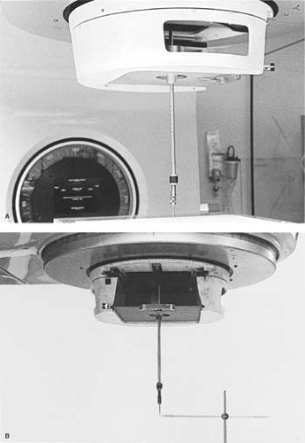 Figure 17.4. Determination of mechanical isocenter. A: Collimator rotation. B: Gantry rotation. See text for details. |
A.4.2. Gantry Rotation
With the wiggler point positioned at the isocenter as determined previously, another horizontal rod with a fine point is held in a ring stand so that the two points coincide as best as possible (Fig. 17.4B). The stand for the horizontal rod should rest on the couch near its end so that there is no possibility of gantry collision with the couch or the apparatus. By moving the gantry through 360 degrees, the displacement between the wiggler point and the horizontal rod point is visually noted and measured. The tolerance of the isocenter motion with full gantry rotation is ±1 mm.
A.5. Radiation Isocenter
A.5.1. Collimator
With the gantry vertical, place a ready pack film flat on the tabletop at the SAD. Open the upper jaws of the collimator wide and close the lower jaws to obtain a narrow slit of minimum possible width. Place a buildup sheet on top of the film. By rotating the collimator through a number of different angles, the film is exposed to obtain an optical density of about 1. The interval between angles should be such that six to seven exposures can be made to cover full rotation of the collimator without overlaps. Using a new film, repeat the above process with the lower jaws open and the upper jaws closed to a narrow slit.
The processed films will show star patterns, with a dark central region (Fig. 17.5A). By using a ballpoint pen or another film marker with a fine point, lines may be drawn through the middle of the slit images to define more clearly the intersection point(s) of the slit images. For an acceptable result, all the lines should intersect or pass within a 2-mm-diameter circle.
A.5.2. Treatment Table
Place a film on the tabletop at the SAD. Open the upper collimator jaws wide and close down the lower jaws to a narrow slit. Place a buildup sheet on top of the film. Make six to seven exposures on the same film with the table rotated through a series of different angles to cover the full range of couch rotation. Some exposures may have to be staggered to avoid
overlap of images. A star pattern (Fig. 17.5B) on the processed film should ideally show all the slit images intersecting at one point, the radiation isocenter. Acceptable specification requires that all the lines should intersect or pass within a 2-mm-diameter circle. Stricter specification may be required for a unit designated for stereotactic radiosurgery.
overlap of images. A star pattern (Fig. 17.5B) on the processed film should ideally show all the slit images intersecting at one point, the radiation isocenter. Acceptable specification requires that all the lines should intersect or pass within a 2-mm-diameter circle. Stricter specification may be required for a unit designated for stereotactic radiosurgery.
Related posts:


Stay updated, free articles. Join our Telegram channel

Full access? Get Clinical Tree


