Fig. 17.1
View of the trachea with the unsheated probe. An image interpretation is not possible
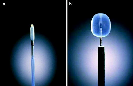
Fig. 17.2
The radial EBUS probe inside the water-fillable balloon sheath, filled and unfilled with sterile water
Radial ultrasound allows for a 360° view of the exact location of a lesion in relation to the airway. This allows for more direct and accurate sampling, increasing the diagnostic yield of the procedure.
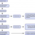
Miniprobes are delicate, fragile devices that must be handled with care. The transducer and the connecting driving wire are protected from friction inside the plastic sheath by a gel solution. The catheter might not be completely air sealed, and small air bubbles can collect in front of the transducer and interfere with the image. Therefore, the devices should be stored in a hanging position with the connector upward and the tip of the probe downward. If a bubble has collected at the tip of the catheter, it can be cleared by holding the probe approximately 40 cm proximally from the tip and rotating it like a lasso to drive the gel peripherally and the bubble proximally. After inserting the probe into the balloon catheter and connecting the proximal end to the connector with the driving unit, the catheter – including the balloon – should be filled completely with sterile water to clear the system from air and make slipping the O-ring over the notch easier. Olympus advice not to use saline solutions as the salt can crystallize on the probe and interfere with imaging. After filling, the O-ring can be slipped onto the tip of the probe with the fingertip or a special rubber device. This should be done gently without bending or kinking the tip. Then, the balloon is filled to expand. If some air bubbles remain, the balloon is kept with its tip pointing down, and the air is removed by suctioning the water from the balloon with the syringe. The syringe should always be held in an upright position so that the air collects above the fluid and is not flushed back into the catheter.
After insertion via the biopsy channel of the flexible endoscope, precise placement of the probe inside the central airways is carried out under visual control. Once the transducer is positioned, the balloon is filled with water until firm contact with the wall is established. Adequate contact is confirmed by a complete circular image of the bronchial wall and the surrounding structures. The development of the image is similar to sunrise, when all the structures gradually become visible. After sufficient preoxygenation with the patient under local anesthesia, inflation of the balloon is possible in bilateral ventilated lungs up to the main bronchi and even inside the trachea. Complete obstruction of a remaining main bronchus after contralateral resection or occlusion of the trachea can be tolerated for up to 2 min with sufficient sedation.
The downside to using a radial probe is that the device must be removed from the bronchoscope channel before other sampling tools can be inserted; therefore, the physician loses the ability to view both the endoscopic and ultrasound images simultaneously while performing the biopsy, which can increase the chance of missing the target site or can reduce the specimen yield. After localization of the target, the probe is pulled out, and the needle is passed through the fiberscope in the retracted position. When the needle is in view, the needle is advanced from its sheath and inserted into the lesions through the tracheal or bronchial wall. After the needle is advanced into the tissue, suction is applied with a 20 ml syringe via a side port at the proximal end of the catheter. The technique is named EBUS-guided TBNA. The disadvantage of radial ultrasound highlights the advantages of the EBUS TBNA scope equipped with curvilinear ultrasound.
The new development is a dedicated bronchoscope with an integrated curvilinear electronic transducer at the tip. So a real-time needle puncture under endoscopic control is possible. The endoscope has a working channel of 2 mm. The ultrasonic frequency is 7.5 MHz with a penetration depth of 5 cm. The scanning direction is parallel to the longitudinal axis of the endoscope with a scanning angle of 50° which enables full ultrasonic monitoring of a needle when inserted via the biopsy channel during scanning but does not provide the necessary resolution for diagnostic imaging.
Sonographic Anatomy
The wall of the central airways shows a seven-layer structure (Fig. 17.3). The layers are representing the mucosa and submucosa, the three layers of the cartilage, and the adjacent external structures of lose and dense connective tissue, respectively (Fig. 17.4). Under low power magnification and in the periphery, only a three-layer structure is visible. Orientation by ultrasound within the mediastinum is difficult. Besides the complex mediastinal anatomy, this is due to motion artifacts by pulsation and respiration as well as the unusual planes of the ultrasonic images as dictated by the course of the airways. For orientation, therefore, the analysis of characteristic anatomical structures is more reliable than observation of the position of the ultrasound probe inside the airway (Fig. 17.5). Vessels can be identified by their pulsation. But even after application of echo contrast media, discrimination of venous and arterial vessels can be difficult due to the great number of variations (Fig. 17.6). However, as during the procedure pulse oxymetry is applied, arterial pulsations can be confirmed according to their synchrony with the acoustic signal. Lymph nodes and solid structures can be differentiated down to a size of few millimeters from the blood vessels by their higher echodensity.
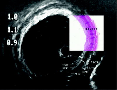
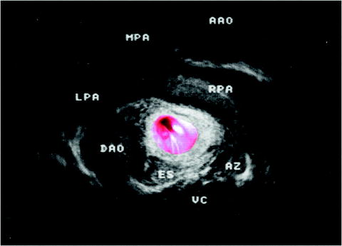
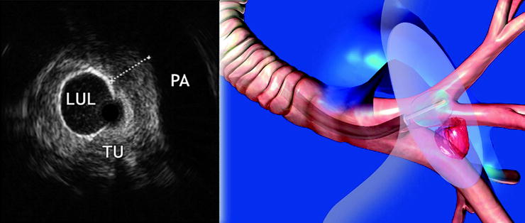
Fig. 17.3
The seven-layer structure of the trachea
Fig. 17.4
The layer structure in detail. The three-layer structure of the cartilage with endochondrium (EC), perichondrium (PC), and spongiform internal structure (IC) is lined by mucosa (MC) and submucosa (SM) internally and by loose (LCT) and dense connective tissue on the outside (DCT). HE stain shows the corresponding structures
Fig. 17.5
US view of a compression of the airways due to the central vessels (AAO ascending aorta, MPA main pulmonary artery, LPA left pulmonary artery, RPA right pulmonary artery, DAO descending aorta, ES esophagus, AZ vena azygos, VC vertebral column)
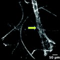
Fig. 17.6
The probe is placed in the upper lobe segment left (LUL), as seen in the animation. In the ultrasound image, the tumor (TU) is visible with close contact to the pulmonary artery (PA)
Related posts:

Stay updated, free articles. Join our Telegram channel

Full access? Get Clinical Tree


