Radio Frequency Pulse
Introduction
In the last chapter, we discussed the concept of longitudinal magnetization. However, we have not yet addressed the issue of receiving a signal from the patient. We can only transmit and receive signals that oscillate (like an AC voltage). In addition, we’re only sensitive to oscillations along certain axes. Because the longitudinal magnetization is not an oscillating function (like a DC voltage), it cannot be read by a receiver. In addition, we’re not sensitive to oscillations along the z-axis. Consequently, this magnetization needs to be “flipped” into the transverse x-y plane (where it can oscillate or “precess” about the z-axis) to generate a readable signal. This is the purpose of the radio frequency (RF) pulse.
RF Pulse
Suppose that a patient is in the magnet. Then we transmit an RF pulse. What happens? Remember that an RF pulse is an electromagnetic wave. Initially, all the spins are lined up along the axis of the external magnetic field B0 about which they are precessing (Fig. 3-1). Then we transmit an RF pulse. In a three-dimensional (x, y, z) coordinate system, the direction of the external magnetic field always points in the z direction. Thus, the net magnetization vector M0 will also point in the z direction (Fig. 3-2).
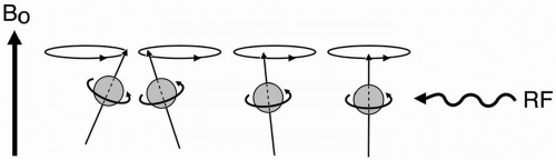 Figure 3-1. An RF pulse is transmitted after the protons have been exposed to the external magnetic field B0. |
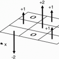
One point of clarification about the magnetization vector M0: even though all of the individual spins are precessing around the external magnetic field axis, the net magnetization (which is made up of the vector sum of all the individual spins) does not precess. The reason for this is that all the individual spins are precessing, but they are all out of phase with each other. Therefore, if we add them all up, they’ll have a large component along the z-axis; however, because of their phase differences, they all cancel each other out and are left with no component along the x- or y-axis (Fig. 3-3). (Note that in Fig. 3-3B, while the two protons are precessing at the same rate, one is pointing toward the right and the other is pointing toward the left.) Thus, the net vector of magnetization does not precess (at least initially—it only precesses in response to the RF pulse—see later text).
Now, let’s transmit an RF pulse along the x-axis perpendicular to the magnetization vector M0, that is, the axis of B0. (The RF pulse would be along the axis “C” in Fig. 2-2.) Any proton
that is subjected to any sort of magnetic field starts to precess about the axis of that magnetic field at a frequency ω0 given by the Larmor equation (ω = γB), where B is the strength of that magnetic field. Protons precess about the axis of B0 at a frequency ω0 = γB0. Now we introduce a magnetic field (namely, the magnetic component of the RF pulse) into the system with a direction along the x-axis. The protons that were previously aligned with the external magnetic field B0 in the z direction will now also begin to precess about the x-axis, that is, about the axis of the new (RF) magnetic field.
that is subjected to any sort of magnetic field starts to precess about the axis of that magnetic field at a frequency ω0 given by the Larmor equation (ω = γB), where B is the strength of that magnetic field. Protons precess about the axis of B0 at a frequency ω0 = γB0. Now we introduce a magnetic field (namely, the magnetic component of the RF pulse) into the system with a direction along the x-axis. The protons that were previously aligned with the external magnetic field B0 in the z direction will now also begin to precess about the x-axis, that is, about the axis of the new (RF) magnetic field.
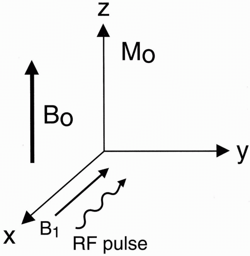 Figure 3-2. The net magnetization vector M0 has the same direction as the external magnetic field B0. |
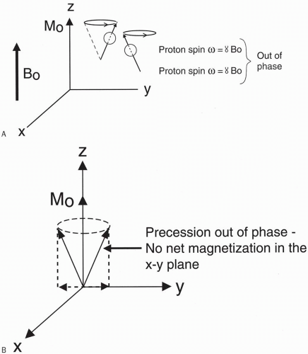 Figure 3-3. Two protons rotating out of phase (A) will lead to a net longitudinal magnetization but no component in the x-y plane (B). |
At what rate will these protons precess around this new magnetic field? The new precessional frequency will be
where B1 is the weaker magnetic field associated with the RF pulse.
B0 is a fixed magnetic field (much like a DC voltage). B1, however, is an oscillating magnetic field (much like an AC voltage). It oscillates because it is derived from the magnetic component of an oscillating electromagnetic wave.
Because the magnetic field strength of B1 is much weaker than the external magnetic field B0, the frequency of precession ω1 of the spins around the axis of B1 is much slower than the precessional frequency ω0 of the spins around the axis of the external magnetic field B0.
So, since B1  B0, then ω1
  ω0.
ω0.
B0, then ω1 ω0.The protons are precessing about the B0 field (z-axis) at frequency ω0 and about the B1 field (x-axis) at frequency ω1 at the same time. This results in a spiral motion of the net magnetization vector from the z-axis into the x-y plane. This spiral motion is called nutation.
Another thing to remember about the RF pulse is that, referring back to Chapter 1, the RF pulse has a cos (ωt) waveform. The frequency ω of the RF pulse should be identical to the Larmor frequency of the precessing protons. Otherwise, the protons will not precess around the B1-axis of the RF pulse. This point might be clarified if we first discuss the concept of resonance.
Resonance. If the frequency ω of the RF pulse matches the frequency of precession of the protons, then resonance occurs. Resonance results in the RF pulse adding energy to the protons. A simple example of resonance is the frequency of a child on a swing. Based on the length of the swing and the weight of the child, a natural mechanical resonance frequency exists. If the child is pushed faster or slower from this frequency, the effort will be inefficient. If the child is pushed at his or her resonance frequency, energy is added and he or she swings higher. Similarly, if the proton precesses at frequency ω0 and the frequency of the RF pulse is not ω0 (say it is ω2 instead), then the magnetic field B1 is oscillating at a different frequency than the protons, and the two frequencies won’t be matched. If the RF frequency does not match the precessional frequency of the spins, the system won’t resonate and no energy will be added.
Consider this in the x-y plane. The protons are spinning at frequency ω0. If we then have the B1 magnetic field oscillating at a frequency = ω2 different from the proton precessional frequency ω0, then the system won’t resonate, that is, the protons won’t “flip” into the x-y plane. A point of clarification: the RF pulse is characterized by two parameters, strength (B1) and frequency (ω2). The frequency of the RF pulse must match the proton precessional frequency ω0 in order for resonance to occur—and for the RF pulse to have any effect on the protons at all. If the frequency ω2 is correct, then the strength of the RF pulse (B1) results in precession of protons about the x-axis at frequency ω1 (according to the Larmor equation ω1 = γB1).
If ω0 and ω2 match (i.e., ω2 = ω0), then the system resonates and the protons flip into the x-y plane. In doing so, the protons precess around the axis of the B1 magnetic field at a much lower frequency (ω1), corresponding to the Larmor frequency associated with the RF


Related posts:
Stay updated, free articles. Join our Telegram channel
Full access? Get Clinical Tree
