Introduction
The upper cervical spine contains the craniocervical junction (CCJ), the atlas or C1, and the axis or C2. A large proportion of overall cervical motion comes from the upper cervical spine between the CCJ and C2. The CCJ accommodates approximately 45 degrees of flexion extension. This is more than any other single cervical level. The C1–2 joint is responsible for approximately 40 degrees of axial rotation in each direction, that is, 40% of total axial rotation of the cervical spine. Due to the significant amount of motion in the upper cervical spine, the ligamentous support of this region is pivotal to maintaining adequate stability.
Ligaments of the CCJ and atlantoaxial (AA) articulations are separated into two groups: intrinsic and extrinsic ligaments. Intrinsic ligaments include the tectorial membrane (rostral continuation of the posterior longitudinal ligament), the cruciate ligament complex, and the alar and apical ligaments ( Fig. 1 ). The cruciate ligament complex contains the transverse atlantoaxial ligament (TAL), the most structurally important part of the complex, as well as longitudinal fibers that extend from the foramen magnum to the axis. The TAL is an essential stabilizer of the AA articulation. Extrinsic ligaments include the ligamentum nuchae, cranial continuation of the anterior longitudinal ligaments, as well as the ligamentum flavum. Three ligaments traverse from the odontoid to the occipital condyles; these include the paired alar ligaments that extend from the cranial tip of the odontoid process to the occipital condyles and a central apical ligament that extends from the tip of the odontoid to the basion.

Plain radiographs were historically the primary tool for the evaluation of cervical trauma. While modalities such as CT and MRI scans have largely taken over the role of initial imaging in the setting of high-energy blunt trauma, radiographs remain as a useful adjunct in the evaluation of the upper cervical spine. Not only are plain radiographs inexpensive and reduce radiation exposure to the patient, they are easy to obtain in the emergency department and in the office postoperatively. Flexion-extension plain radiographs can also be obtained providing information that is not obtained via CT and MRI. Radiographic evaluation of the upper cervical spine begins with obtaining an anteroposterior (AP) view, an open-mouth odontoid view, and a lateral view. When performed correctly, radiographs will include the base of the skull to the upper border of T1 on lateral radiographs and the C3-T1 vertebrae on AP radiographs. The spinous processes and facet joints should be well aligned and symmetrical as any asymmetry would indicate rotation. A number of specific injuries, classifications, and measurement techniques are discussed later.
Occipital Condyle Fractures
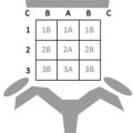
Occipital condyle fractures are most reliably identified with a thin-slice CT scan of the cervical spine. However, these injuries may be present on plain radiographs, and a general knowledge of their morphology is useful in order to maintain a high level of suspicion for their presence in the setting of blunt trauma. Currently, the most commonly used classification system is the Anderson and Montesano classification. This system describes three types of occipital condyle fractures: Type 1, comminuted; Type 2, extension of a basilar skull fracture; and Type 3, avulsion. It is important to note that Type 3 fractures are associated with craniocervical dissociation (CCD) injuries. Occipital condyle fractures are not obvious on plain radiographs, and thus, a CT scan should be used if there is suspicion for this injury.
Craniocervical Dissociation
A craniocervical dissociation (CCD), otherwise known as “occipitocervical dissociation” (OCD), is a rare, but severe injury in which the stability between the cranium and the cervical spine has been compromised. This requires disruption of the stabilizing intrinsic and extrinsic craniocervical junction (CCJ) ligaments. Injuries to the CCJ typically require a high-energy mechanism, which usually involves a rapid deceleration with or without cranial impact. These are most commonly seen in the setting of motor vehicle accidents or falls from significant height and are often fatal. Accurate and early diagnosis and treatment of these patients is critical to optimize their outcomes. The osseous anatomy of the craniocervical junction in the traumatized patient is rather difficult on plain radiographs due to the complex anatomy and overlying structures. Many methods have been described to evaluate the craniocervical junction on plain radiographs. These radiographic parameters help define normal anatomy and aid in the diagnosis of various pathologic conditions such as instability and superior migration of the dens. Radiographic parameters have inherent weaknesses as the variability exists in magnification, interobserver measurements, and normal anatomy.
Harris Lines (BAI and BDI)
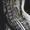
Harris lines are a common measurement used to diagnose potential occipitocervical dissociations on a lateral cervical spine radiograph. This was first described by Harris et al. They involve two measurements: the basion-dental interval (BDI) and the basion-axial interval (BAI). The BDI is measured from the basion to the tip of the dens and is considered abnormal above 12 mm. The BAI measures the distance from the tip of the basion to a line extending superiorly from the dorsal aspect of the dens, or the posterior axis line (PAL). The BAI should also be less than 12 mm. Together the two Harris line values are thought to be more diagnostically accurate than the Power’s index/ratio in identifying CCD injuries ( Fig. 2 ).

Power’s Ratio
The Power’s ratio is another measurement used in the diagnosis of occipitocervical dissociation. It is calculated from the ratio of the distance from the basion to the ventral aspect of the posterior arch of C1, compared with the distance from the tip of the opisthion (posterior foramen magnum) to the center of the dorsal aspect of the anterior arch of C1. An accepted ratio is less than or equal to 1, with value greater than one considered abnormal and suggestive of ventral atlanto-occipital dissociation. Ratios approaching 0.7 or less are concerning for dorsal atlanto-occipital dislocation ( Fig. 3 ). A concern with the Power’s ratio is that if both of the distances used in the ratio increase proportionally, such as in a primarily distraction injury; therefore, the ratio would remain normal in the presence of an OCD injury.

Wackenheim’s Line
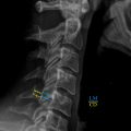
Wackenheim’s line is drawn along the superior surface of the clivus and extending caudally. The odontoid process should not protrude posterior to the projection of this line on the lateral X-ray ( Fig. 4 ).

Chamberlaińs Line
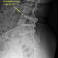
Chamberlaińs line is drawn from the posterior tip or pole of the hard palate to the opisthion, or dorsal margin of the foramen magnum. The tip of the odontoid should project less than 3 mm above Chamberlaińs line. A projection of the odontoid above this point suggests a basilar invagination. ( Fig. 5 ).

McGregor’s Line
McGregor later developed a modification of Chamberlaińs line that can be applied when the opisthion cannot be accurately identified on X-ray. This line, termed McGregor’s line, extends from the posterior tip or pole of the hard palate to the lowest point of the midline occipital curve. In a normal study, the tip of the odontoid should project less than 4.5 mm above this line. Typically, the odontoid will lie below or just tangent to Chamberlaińs line and McGregor’s line ( Fig. 6 ).

Related posts:
 Full-Length Spine—Plain Radiographs
 Upper Cervical Spine: Computed Tomography
 Clinical Correlations to Specific Phenotypes and Measurements With Classification Systems: Lumbosacral Spine
 Clinical Correlations to Specific Phenotypes and Measurements With Classification Systems
 Magnetic Resonance Imaging Techniques for the Evaluation of the Subaxial Cervical Spine
 Lumbosacral Spine Plain Radiographs
Stay updated, free articles. Join our Telegram channel

Full access? Get Clinical Tree


