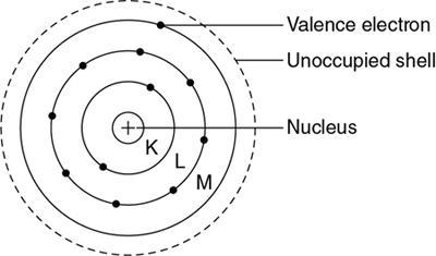
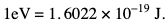
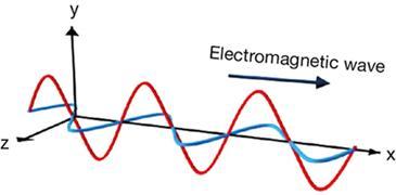
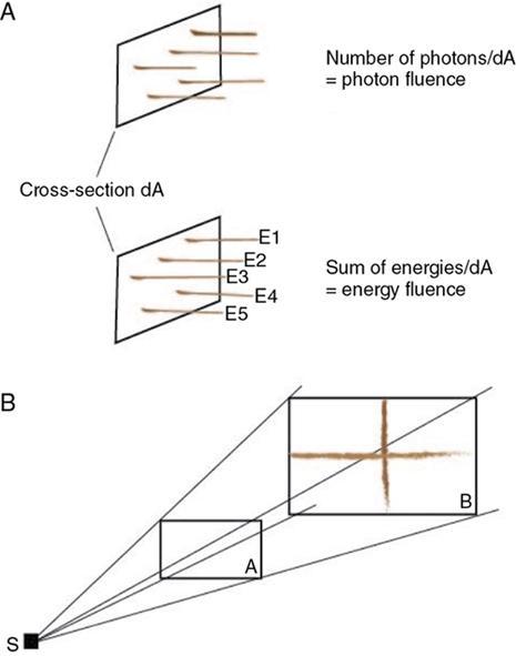
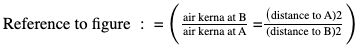
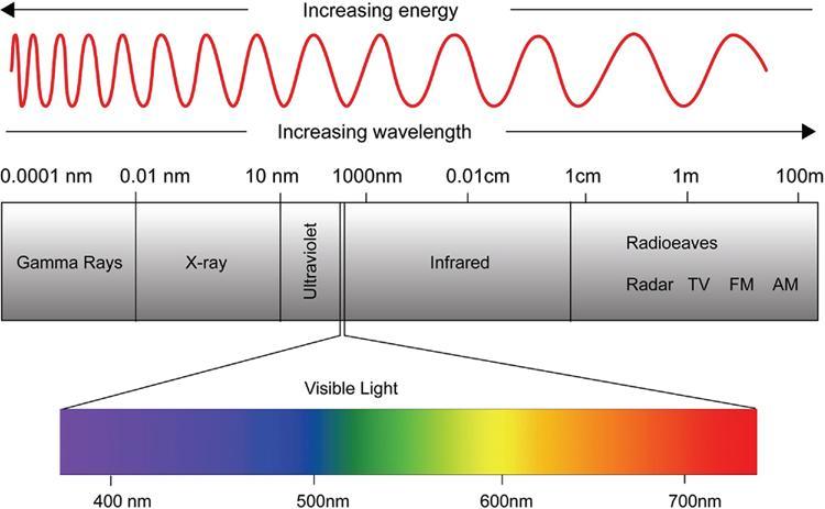
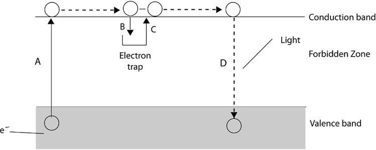
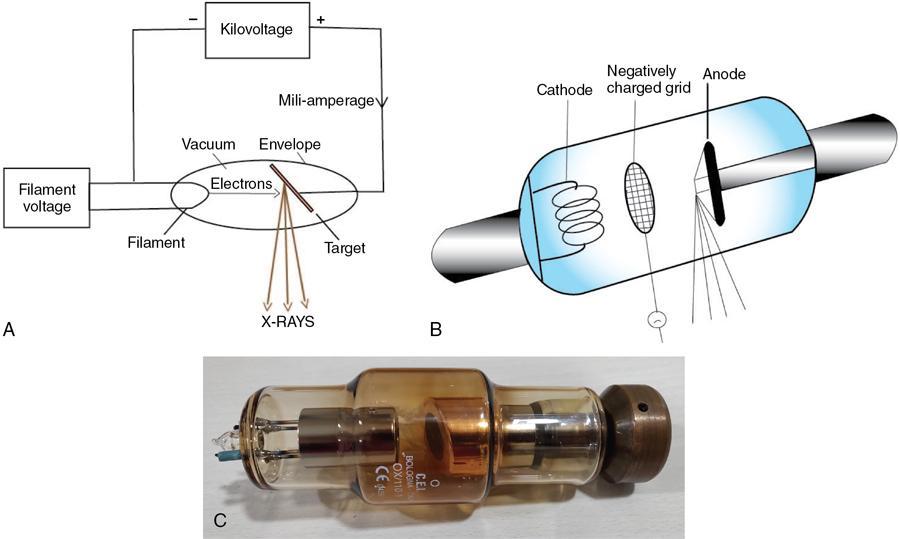
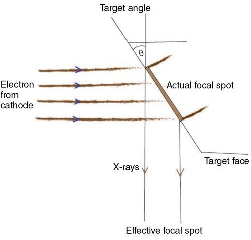
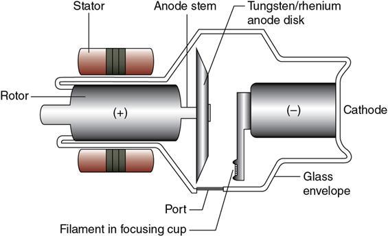
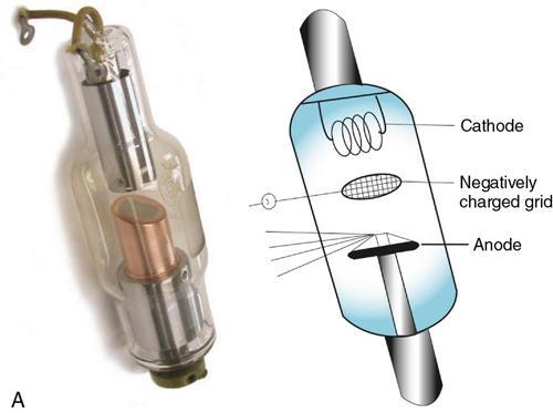
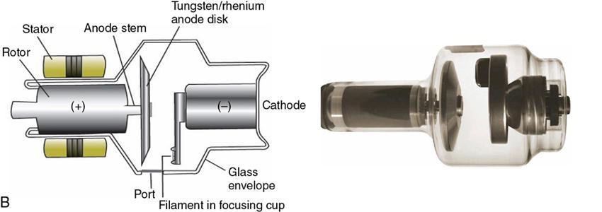
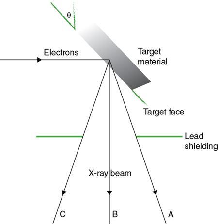
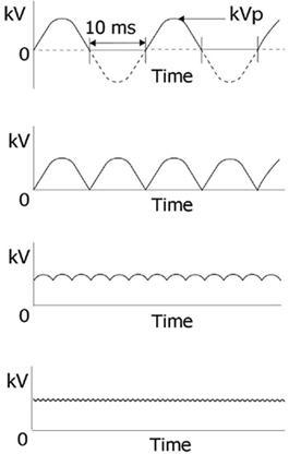
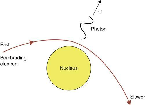
Nidhi Goyal, Arif Mirza, Abhishek Suman Remove radiology from medical science, and a vast majority of medical cases can become unreasonably difficult to be solved. Haider Imam BASIC PRINCIPLES: RADIATION PHYSICS A German mechanical engineer and physicist, Wilhelm Conrad Roentgen, on 8 November 1895, discovered electromagnetic radiation in a wavelength range of 10 to 0.1 nm known as X-rays. By 28 December 1895, he investigated the properties of X-ray and prepared a manuscript, for which he received the first Nobel Prize in Physics in 1901. X-rays are a form of electromagnetic radiation. Diagnostic imaging uses radiation – X-ray, gamma rays, radiofrequency and sound – and exploits the special properties of various elements and compounds. The ionizing radiations used in radiography are X-rays and gamma rays. Large component of atom consists of empty space and smaller component is of mass which is concentrated in the central nucleus. Atom consists of three basic particles, named protons, electrons and neutrons. Central nucleus contains protons, positive charged particle (Z) and neutrons neutral particle. The total number of protons and neutrons the called nucleons numbered A termed mass number of the atom. Z is the atomic number of the element, with A–Z are neutrons. Describing an atom: X Z A The atomic number is synonymous with the name of the element. Orbiting in specific shells, around the positively charged nucleus, are electrons which are negatively charged particles of an atom. The designated shells named K, L, M, N,…. from the centre outwards. Fig. 1.6.1.1 illustrates the structure of an atom with a nucleus in the centre and electrons in the respective orbits. The outermost shell is called the valence shell which contains a maximum of eight electrons at any particular time and is responsible for the chemical, thermal and electric properties of the element. The electrons in the inner shells are responsible for the properties of X-rays and interaction with the material. Radioactivity concerns the nucleus. The electrons in the valence shell are considered free and account for the good conduction of heat and electricity. The binding energy I of the electron in an atom is the energy required to completely free the electron from the atom against the attractive force of the positive nucleus. The binding energy increases as the atomic number increases and it is different for different orbital shells in an atom EK > EL > EM and so on. The binding energy of electron is expressed in electron volts (eV) or keV (1 keV = 1000 eV) (Table 1.6.1.1). 1 eV = 1 . 6022 × 1 0 − 19 J . Points to remember: Definition: Electromagnetic radiation is the term given to the energy travelling in open space as a combination of electric and magnetic fields, propagating perpendicular to each other, like a sinusoidal variation of magnetic and electric fields in space (Fig. 1.6.1.2). There are various forms of electromagnetic radiation and all forms travel in space with the same velocity (c = 3 × 10⁸) as light when in vacuum and slightly less in air. The electromagnetic rays are named according to the source and the special properties they possess. X-rays are emitted by X-ray tubes and gamma rays emitted by radioactive nuclei are differ in their origin, however, have similar properties. Classification of radiation: Ionizing radiation can be either directly ionizing or indirectly ionizing radiation. Directly ionizing radiations interact with the material and deposit energy through the interaction with the directly ionized charged particles and orbital electrons of atoms. Both alpha and beta particles are charged particles and are examples of directly ionizing radiation. Indirectly ionizing radiation release energy in two steps, the first step is the release of the charged particle in the medium and in the second step the released charged particles interact with orbital electrons of the atom to deposit energy in the medium (photons interaction with material releases electrons or protons and these electrons/protons then interact with orbital electrons). X-rays and gamma rays are indirectly ionizing radiation interacting through the secondary electrons. Electromagnetic rays are assumed to be composed of particles and waves and possess both particle and wave properties. Wave concept of electromagnetic radiation: Electromagnetic radiation can be regarded as transverse waves that travel in line with a velocity of light (c) with sinusoidally varying electric and magnetic fields and both vectors pointing at a right angle to each other and to the direction of travel of wave (Fig. 1.6.1.2). The highest points in this sinusoidal wave are crests and the lowest points are troughs. The waveform showing field strength against time or distance of a propagating wave is depicted as a sine wave on a solid line (Fig. 1.6.1.3). The maximum height of the wave from its baseline against time depicts peak wave strength called the amplitude of the wave (A). The interval between two successive crest/troughs of a propagating wave is called the period (T) (Fig. 1.6.1.3A). The number of crests/troughs passing through a given point per second is the frequency (ƒ). The frequency is inversely proportional to the time ƒ = 1/T. The graph of field strength against distance is also a sine wave and the distance between two successive crests or troughs or the entire distance covered by one complete crest/trough is called wavelength depicted by lambda (λ) Fig. 1.6.1.3A. The speed of the electromagnetic wave, frequency and wavelength are interrelated through an important equation: where the product of wavelength and frequency = constant = velocity (λ × ƒ = c). As the velocity remains more or less constant, the wavelength and frequency of radiation are inversely proportional to each other (Table 1.6.1.2). Units = m (metre) Units = seconds f = 1/T Units = Hz 1 Hz = 1 cycle per second Velocity = frequency × wavelength C = f × λ Particle/quantum concept of electromagnetic radiations: The quantum aspects are particle-like properties and represented by quanta of energy/bundles of energy called a quantum, or photon. The electromagnetic waves with less wavelength such as X-ray react with the matter as particles. A photon of certain energy (>15 eV) is capable of ionizing the atoms and X-rays, gamma rays are ionizing radiation capable of ionization of the medium. The energy of photon particle is measured in joules (J) and in electromagnetic radiation it’s measured in electron volts. 1 eV = 1.6 × 10⁻¹⁹ J. Wave and quantum properties combined: Photons travel at the speed of light and the unit to measure the energy of photons is electron volt (eV). When accelerated in the potential difference of 1 V, the energy gained by the electron is electron volt. This photon energy or field strength is related to the characteristics of the wave and the relation is through Planck’s constant. The total possessed energy of a photon is calculated by multiplying its frequency with Planck’s constant. Planck’s constant in the SI unit is 6.62 × 1034 J/s. E in ( Kev ) = hf E = ev = electron volt is the unit for photon energy, h = Planck’s constant, f = frequency. The photon energy is directly proportional to frequency and inversely proportional to wavelength so photon energy is also depicted by E (in keV) = 1.24/λ (in nm). The energy of wave increases with frequency and decreases with wavelength. When the photon possesses enough energy and is capable of ionizing atoms, it is called ionizing radiation. An atom is ionized after losing an electron and gamma rays, X-rays are all ionizing radiation, as discussed. Radiation travels in straight lines and tends to radiate in all directions as it moves farther from the point source. A collimated set of rays is called a beam and a beam of radiation is visualized by taking a cross section at a point right angles to the beam. Fig. 1.6.1.4 depicts a beam emanating from a point source and as the beam spreads it moves away from the source (area B is larger than area A in Fig. 1.6.1.4). Photon Fluence: The number of photons per unit area at a given cross section of the beam at a given time is called photon fluence at that time (Fig. 1.6.1.4A) (number of photos in area A or B in Fig. 1.6.1.4). Energy Fluence: Adding the total energy of all the photons per unit area, at a given time at a given cross section of the beam gives the energy fluence at that area (Fig. 1.6.1.4A). Energy Fluence Rate: The total amount of energy passing through a specified cross-sectional area per unit time (watts mm2) is called the energy fluence rate at that point (total energy per second of photons in the area depicted A and B). This energy fluence rate is referred to as the beam intensity. In the wave theory, the intensity of the beam is proportional to the square of the amplitude and measured from the peak of the wave to the axis. Energy fluence in the case of X-rays and gamma rays are measured indirectly and called air kerma and intensity: air kerma rate. Inverse-square law: Electromagnetic rays travel in straight lines and as the beam travels farther away from the source, the area of beam increases and the dimensions of the beam is proportional to the distance travelled (Fig. 1.6.1.4B). The area of the beam is usually the square of the distance travelled: A ∝ d 2 A = area, d = distance. Therefore, the same number of photons and photon energy is now spread over a bigger area and thus the intensity/air kerma rate decreases and is inversely proportional to the area. Reference to figure : = ( air kerna at B air kerna at A = ( distance to A)2 (distance to B)2 ) This is true in ideal conditions when radiation is coming from a point source and there is no absorption or scatter of radiation happening between the point source and area of measurement. So if the distance of source doubles between A and B in Fig. 1.6.1.4, then the air kerma reduces by a factor of 4. Electromagnetic spectrum: Electromagnetic spectrum is shown in Fig. 1.6.1.5. The types of electromagnetic radiation are listed in table and is in the order of decreasing wavelength, increasing frequency and photon energy. The boundaries between the types of radiation are nor clearly defined except for visible light where the boundaries are defined by human eye. The nomenclature of various electromagnetic radiation used in normal practice is also highlighted (Table 1.6.1.3). Points to remember: SI units for measurements used most commonly are mentioned in the table below and other units are derived from these basic units. For example unit of energy joules (J) is 1 kg/m2/s2. It is important to mention the multiplying factors of units to define the various quantities (Table 1.6.1.4): Luminescence is a term used to describe a process of emission of light by a substance when exposed to an external source of energy like ionizing radiation. The external source of energy can be any form of chemical, biological and physical source and in radiology, it is the radiation source called photoluminescence. Luminescence can be either fluorescence and phosphorescence, where The material that has luminescent properties is described as a phosphor. The crystalline form of material with luminescent properties used with gamma radiation is referred to as a scintillator. The process behind the luminescence is explained in Fig. 1.6.1.6. In an atom, the electrons occupy the shells with discrete binding energies. Commonly the individual atoms are combined in a molecule such that the valence band, the outermost energy band is full of electrons. The next higher energy band will be vacant and is referred to as the conduction band, which allows the free movement of electrons. Between these two energy bands is the forbidden zone that is usually not occupied by electrons. Within the materials, there are impurities (which are introduced deliberately in commercially available phosphor). These impurities have energy levels different from the main phosphor and may create energy shells within the forbidden zone that are unoccupied, referred to as electron traps. When exposed to radiation as in radiography, the absorbed energy will cause excitation in the molecule of the material resulting in electrons being raised from the valence to the conduction band as shown in Fig. 1.6.1.6. Once in the conduction band, there is free movement of an electron, which comes in the vicinity of impurities, which can move to the electron trap. The electron trapped in the electron trap cannot come to the valence band till there is a space available. With the absorption of energy, the electron can move to the conduction band, creating a space in the valence band, allowing the electron to fall down from the conduction band to the valence band. The energy thus liberated is emitted in form of light, and the intensity of the light emitted is proportional to the intensity of the X-ray beam. 4.1 Diagnostic X-ray tube and Various tubes 4.2 Mechanism of X-ray production/producing an X-ray beam Outline: X-ray tube: X-rays are produced through conversion of kinetic energy of electrons into X-rays. This is achieved when fast moving electrons are suddenly decelerated/stopped by metal target acting as anode. It’s only the 1% of the kinetic energy that is converted to X-rays and about 99% of the rest of the energy is dissipated as heat. The structure of X-ray tube is shown in Fig. 1.6.1.7. The X-ray tube consists of two electrodes enclosed in an evacuated (vacuum) glass envelop housing. Glass envelope: The glass is made of Pyrex to avoid damage due to different coefficient of linear expansion of electrode (cathode) and glass. X-ray tube is a vacuum containing cathode and anode to prevent collision of electrons and hence deviation from path and loss of energy. Cathode: The negative electrode of the X-ray tube is a cathode made of tungsten coil/filament. The filament is about 1 cm in length and 0.2 mm in thickness and the spiral has a 0.2 cm diameter. Tungsten is used to make filament as it can be drawn into a thin wire, is a very strong metal and has a high melting point (3370°C) and less propensity to vaporize thus resulting in an increased life span of cathode filament. Filament: The filament is heated through an electronic current passed through tungsten and at high temperatures like 2200°C, there is the emission of electrons by a process called thermionic emission. The electrons from the outer shell out of the metal are emitted by the absorption of thermal energy. These negatively charged electrons form a small cloud in the vicinity of filament forming a “Space Charge.” With high thermal energies (approx. 2700°C) the motion of the electrons is sufficiently high to enable few electrons to leave the surface. These electrons are then attracted towards the positive anode and move smoothly in a vacuum without any distraction on the way. Focussing Cup: the filament is set in a rectangular slot, in the cathode referred to as focussing hood or cup. Focussing cup surrounds the filament and is made of molybdenum and has a high melting point with poor thermic emission property to avoid the emission of unwanted electrons, which can interfere with the main electron beam released from the filament. It’s negatively charged to direct and focus the stream of electrons accelerating towards the anode. Most X-rays tubes have two filaments one longer and the other smaller in size with one of the filaments used at any point in time. The two filaments are mounted next to each other and larger filament is used for larger exposures. Anode: Anode is the positively charged electrode of the X-ray tube. It’s a smooth small plate of metal made of Tungsten (90%) and Rhenium (10%), for the similar characteristics as in cathode. The small area on anode which receives the high energy electrons emitted from the cathode and accelerated in the vacuum tube is called target. The target stops the electrons and produces X-rays. Tungsten target is a disc about 10–15 mm in diameter with about 1 mm thickness. It is set in a cylindrical block of copper. As already stated most of the energy carried by electrons as they are accelerated from cathode to anode is deposited in the tungsten as heat with a very small energy component converted to useful X-ray photons. This heat is transferred to the copper by conduction. The stem of the copper is connected to the positive side of the high voltage supply through the glass wall of the X-ray tube. The X-ray tube within the housing is surrounded by the oil which acts as an insulator. The heat conducted through the copper anode is transmitted into the oil, which sets convection currents in the oil and thus transmitted to the tube housing and then dissipated into the room. The radiology investigations requiring high exposures will lead to rise in target temperature which may result in the melting of the target and should be overcome by spreading the heat over a large area of the target and by increasing the exposure time duration. On the other hand, to achieve a good quality image, minimizing geometric and movement unsharpness, the focal area should be small and exposure time short. Two new concepts and principles were introduced to address this opposing requirement through two aspects of X-ray tube design: (A) Focal spot size: line focus principle Stationary X-ray tube: It contains a stationary anode made of tungsten embedded in a large mass of copper. Few terminologies need to be understood: The target is the point in the anode where the electrons hit the anode and are also called the focal point/focal spot. As discussed the kinetic energy of the electrons bombarding the metal target is converted to X-rays in 1% of cases and the rest of it is dissipated as heat. The focal spot is the area of the tungsten anode that receives the fast-moving electrons. The heat produced by these electrons is uniformly distributed over the focal spot. Therefore, to avoid damage to the target tungsten, a larger focal spot is preferred for heat dissipation. However, for acquiring good radiographic quality and detail in an image a smaller focal spot is required. To overcome these requirements line focus principle is developed (Fig. 1.6.1.8). Therefore, the target tube is tilted to create an effective/apparent focal spot which seen from the centre of the imaging device is foreshortened in one direction and appears circular or elliptical depending on the exact design of filament, focussing hood, and the target angle. The surface of the target metal tungsten is inclined at an angle varying from 6 degrees to 20 degrees. This way, the projected/apparent focal spot is smaller than the actual focal spot. The target angle “θ” is the angle between the central ray of the X-ray beam and the target face (Fig. 1.6.1.8). This projected focal spot is then directly related to the sine of the angle of the anode. The steeper the target angle (i.e. smaller θ) the greater is the foreshortening. Thus, the use of the steeper target serves to increase the target heat rating for a given effective focal spot and vice versa. However, the steeper the target the narrower is the useful X-ray beam and the smaller is the side coverage field/area. The steeper targets are appropriate in mammography and cardiac angiography for small fields of view with requirements of very high image quality and detailing. In general radiography using larger images, a shallower target angle suffice and is better. Focal spot size is depicted in terms of apparent focal spot created due to line focus principle and the most common sizes are 0.3, 0.6 and 1.2 mm, with 0.3 mm for mammography (0.1 mm magnification), 0.6–1.2 mm for general radiography, 0.6 for fluoroscopy and 0.6–1.0 for CT scanning. The focal spot size is usually not constant and depends on mA and kV both; as mA increases, the focussing of the electron beam becomes less effective, referred to as blooming. This phenomenon becomes more significant at lower settings of kV. (B) Rotating anode tube: the other way to overcome overheating in the target is to rotate the anode during the exposure. The basic design of a rotating anode tube is shown in Fig. 1.6.1.9. The rotating anode is the bevelled disk into which is set an annulus of tungsten which rotates during exposure. The filament assembly is similar to that used in stationary anode tube, but its offset from the centre of the tube. The electron stream is directed to the focussing edge of the rotating disk. The target is heated over the focal area, and because of the rotation of the tube, it is spread over a much greater area. The exposure time usually has to be greater than the period of rotation, for the heat to spread over the entire circumference of the disk. Which is generally 200–300 mm on the other hand in stationary X-ray tube the heat is confined to a narrow strip with a width corresponding to the focal spot size, i.e. 1 mm. The anode assembly in rotating anode tube consists of Rotation is made possible by an induction motor, a device that derives the rotating anode assembly, without a direct connection to the rotating parts. The induction motor consists of external coils, which operate on the alternating current which generates a magnetic field and that induces a current in the rotor. The currents generate opposite magnetic fields that derive the motor round and at a speed of about 3000 rpm or 50 Hz, the frequency of the mains supply. The full rotation takes place in about 20 ms and as there is no direct connect, there is a very small lag in the initiation of rotation and before the anode comes to its full speed of rotation in about 1 s. The anode will take a longer time to halt even after the stator coils are de-energized and reverse braking potentials are applied to bring the rotation to stop. The high-speed anodes are energized with three-phase mains and rotate at 9000 rpm. Anode cooling: Heat produced at the focal point is dissipated into the anode disk, and then transferred to the insulating oil through radiation. The molybdenum stem is sufficiently long and narrow to control the amount of heat conducted to the rotor, without getting overheated and without seizing. Heat radiation is promoted by blackening of the anode assembly. The rate of heat dissipation is related to the temperature being proportional to the fourth power of temperature (expressed in K). Therefore, a 40% increase in the output of the X-rays and accompanying heat involves about a 10% rise of temperature. Thus, there is the requirement for the disk and the stem, to have good thermal properties with a high melting point and low conduction rate in its stem. Heat is conducted to the oil and transferred by convection to the housing, which is then lost by radiation. In few X-ray tubes, a fan assisted convection is used for dissipation of heat as a part of the build of the tube unit. High powered tubes like the one used in CT and angiographies circulates the oil through an external heat exchanger. The oil in tube housing usually expands with heating and therefore bellows system is utilized in housing to allow the expansion. The oil used also serves as an electric insulator. There is the lead lining of the housing unit to prevent the emission of radiation in multiple directions. Choice of the tube type: Rotating anode tube is used in the majority of X-ray applications, however it’s much more expensive than the stationary anode tube. Because of the cost involved, the preference for simpler radiographic techniques is the stationary anode tube, like dental radiology. For longer low mA procedures like fluoroscopy, the stationary anode tube is a more cost-effective alternative. Other examples are mobile fluoroscopy units used in orthopaedic theatre and in temporary pacemaker insertions. Similarly, if the usage of the system is limited to lesser radiographic exposures, at higher mA, as in ward radiography, a stationary tube is sufficient. Heat Rating: The heat loading of the X-ray is expressed in joules and is calculated by kV × mAs for a constant potential or three-phase system and for a single-phase system is 0.7 × kV × mAs. Therefore, the equation of heat unit is expressed as Heat unit (in joules (J)) = kV × mAs, kV = kilovoltage; mAs = current exposure time product. Heat capacity is the capacity to dissipate heat without getting heated and higher heat capacity means the rise in temperature of the material is less with an increase in heat input. Each X-ray unit has a different heat dissipating capacity without damage to the machine. Tube rating is a way to measure the heat dissipation capacity. The capacity for each focal spot for an X-ray machine is given by the tube rating chart provided by the manufacturer. These are displayed in terms of kV/mA (maximum power) that can be used for a given exposure time without overloading or heating the system more than a specific point. In order to capture an image individual exposures should be kept as small as possible and limited by the heating of the X-ray tube. A combination of kV, mA and exposure time should be controlled in a way that the rise in temperature of X-ray should not exceed the safe value specified, otherwise, the target may vaporize, melt, and resultant premature roughening of the surface. The allowable mAs at a particular kV increases as the exposure time increases and conversely, if the mAs can be reduced, the exposure time can be made shorter. The tube rating is stated as allowable mA, and depends on multiple factors: The control monitor/system for the X-ray equipment is designed so as to prevent exposures above the tube rating. Investigations requiring repeated exposures like angiography, heat accumulates in the anode assembly and in the oil. Neither of these should be allowed to exceed maximum heating capacity for the fear of breakdown. The rapidity with which exposure can be made depends upon the capacity to store the heat and rate of dissipation of heat (Fig. 1.6.1.10). The heating capacity for standard radiography units is about 250 kJ and for angiography, it may exceed 1 MJ and up to 5 MJ for X-ray tube used in CT scanner. The generator-controlled systems should limit the total exposure time at the user end so that the heat capacity of the X-ray tube is not exceeded at the required kV and mA. Other ratings and considerations: There is a maximum kV that can be applied and a maximum mA that can be drawn without heating the filament beyond a certain temperature. In general X-ray tubes for diagnostic radiology do not operate above 150 kV, and the maximum mA for routine radiography is about 700 mA. Generators used to produce the high voltage supply have a rating given in kW and is usually in a range of 40–60 kW. This limits mA at particular settings; for example, a 50-kW generator cannot operate above 500 mA at 100 kV but can operate at 625 mA at 80 kV. Cooling of X-ray tube: The composition of the anode with two materials one with a high melting point (tungsten) and the other with high conductivity to heat (copper) helps in cooling the anode. The other cooling methods used are Uniformity of the X-ray beam and anode heel effect: The X-ray beams get attenuated as they exit out of the target material as they penetrate the target. A part of the X-ray photons produced has to traverse through the target material responsible for attenuation/filtration, causing a decrease in the intensity. The attenuation of the X-ray beam thus produced is not uniform as the target is at an angle and X-rays travelling towards the anode edge of the field (A) have to cross more target material and therefore, attenuated more than those towards the cathode edge (C) (Fig. 1.6.1.11). The intensity of the beam thus coming out of the target has different intensity across the field from cathode to the anode side of the X-ray tube. The fact that intensities vary in such a manner causes a visible difference in the density on the radiograph acquired. This phenomenon is called the “heel effect” (Fig. 1.6.1.11). The maximum intensity of the useful beam is determined by the angle θ of the anode and that is responsible for the “heel effect.” Decreasing the anode angle will result in a smaller effective focal spot size, useful in imaging, but a larger anode heel effect. The heel effect results in a less uniform and attenuated beam. The heel effect being gradual over the field is not very much noticeable on X-ray film, though the resulting radiograph of an object of equal density and thickness may appear darker on the cathode side of the film and lighter on the anode side of the film. The heel effect can be made advantageous in capturing a radiographic image when patient thickness varies in the field of view to be taken. The thicker or denser part of the patient should be placed towards the cathode end, of the tube where the exit beam is more intense. The heel effect is more visible on a larger image than a smaller image. The intensity of the beam decreases on either side of the central ray because of inverse square law, the X-rays at the edges have farther to travel. There are two limiting factors in X-ray imaging, the amount of heating acceptable for the X-ray tube and permissible radiation dose to the patient. Other limiting factors come from the receptor side of the image formation including sensitivity and performance of the film-screen radiography or other receptor media, like digital detectors and is dealt individually in later sections. The sources of electrical energy are required for the functioning of X-ray tubes to produce X-rays. This energy is derived from AC mains by means of transformers. One source is required to heat the filament for the emission of electrons through thermionic emission and the filament heating voltage is about (10 V) and current (10 A). The other is accelerating voltage (30–150 kV) applied between the anode and cathode referred to as the tube potential, high voltage or kilovoltage (kV). This voltage source is required for accelerating the electrons in the tube for deriving the current of electron between the cathode and anode (referred to as tube current, milliamperage, or mA) and is typically between 0.5 and 1000 mA. The two sources of electrical energy should remain independent, that is the increase or decrease in the tube voltage will not affect the tube current (mA) and thus the two factors can be varied independently. The accelerating potential applied across the X-ray tube is the function of the X-ray generator. The voltage potential applied normally is between 50–150 kV for radiography, 25–40 kV for mammography and about 40–110 kV for fluoroscopy. The central energy is derived from AC mains. Generator and Rectifier and Transformer: An X-ray generator is a part of the X-ray unit, which as a device provides the electrical energy from mechanical energy, and supplies the electric power to the X-ray tube for the filament heating and providing a voltage across the tube. The generator mechanism is divided into two compartments: a control panel also called a console and a transformer assembly. The console provides an external control through which the operator can choose the appropriate kV, mA and exposure time required for a particular radiograph or radiographic examination. The second component is the transformer assembly, which is a metal box containing low and high voltage transformers and a group of rectifiers immersed in oil where oil serves as an insulator. Transformer increases or decreases the voltage in a circuit and rectifier changes alternating current to direct current. The generator contains three circuits, one for heating filament, one for providing accelerating voltage and the third one is a control panel, which regulates the X-ray exposure. The former two circuits are part of the transformer assembly and a last control panel is a separate unit. The role of the transformer is to increase or decrease the voltage in a circuit and the rectifier changes the AC main supply into DC. Transformers used in X-ray machines produce high voltage from low voltage AC supplies of the mains to give a waveform depicted in Fig. 1.6.1.12. AC as shown in Fig. 1.6.1.12 has positive and negative phases of the kV cycle. The forward current is responsible for heating the filament and thus generating electrons. This is a single phase – self-rectified generator (Fig. 1.6.1.12A). This is used in dental radiography equipment. Rectification is the process that converts the negative part of the waveform into the positive kV, and in its simplest form converts the standard waveform into the pulsating direct current (DC) waveform. As seen in Fig. 1.6.1.12B called full-wave – rectified single phase. When three phases of mains supply are used to produce a near-constant potential with a small ripple, as shown in Fig. 1.6.1.12C, it is called three phase generator. The three-phase generator has 6 to 12 pulses per cycle and an associated ripple theoretically equal to 13% and 4%, respectively. These are no more used in clinical practice nowadays. Modern present-day X-ray equipment is high frequency (HF) generators (Fig. 1.6.1.12D), in which the mains is converted to a steady high-voltage DC supply with about 1% ripple. HF generators are very stable and compact in size. The rectification helps in The tungsten filament is heated by an independent current through generator to emit electrons: a process called thermionic emission. The emitted electrons are accelerated to the anode across the potential difference created by external source. The focussing cup directs the stream of electrons across the vacuum to hit the focal spot on the anode. The interaction at the target filament of the X-ray tube: There are two main mechanisms for the production of X-rays. The electron hitting the target anode losses the kinetic energies in many ways. Elastic interactions occur rarely and happen only with electrons having kVp less than 10 eV. The more important are inelastic interactions which are responsible for excitation/ionization in atoms and release thermal energy and X-rays (electromagnetic radiations). Therefore, at the anode, electrons can interact with the atoms of the anode in several ways summarized as low energy interactions resulting in loss of energy in way of heat. The other is large energy interaction responsible for the production of the X-rays. This interaction is depicted in Fig. 1.6.1.13, when a high-energy bombarding electron collides with an electron in the K-shell of the atom, the electron will be ejected from the atom, provided the energy of the bombarding electron is more than the binding energy of the K-shell. The vacancy or hole created in the K-shell is most likely to be filled in by an electron from the outer L-shell of the atom and in doing so the energy is released in the form of a single energy photon. The energy of the photon is precisely the difference between the energies of two shells, Ek–El. The photon energy is referred to as K α radiation. Alternatively, if the empty space created in the K-shell is filled by an electron coming from M-shell, then the emission of the single X-ray photon with the photon energy equivalent to Ek–EM is referred to as Kβ radiation. In the case of the standard target material used in medical X-ray tubes tungsten (Z = 74) Ek = 70 keV, EL = 12 keV and EM = 2 keV. The Kα radiation will have photon energy of about 58 keV and Kβ radiation has a photon energy of 68 keV. The bombarding electron when releases energy continues its path and is diverted. The X-ray photons thus produced have a few discrete photon energies corresponding to the binding energies of different shells and constitute a line spectrum. The released energy is called characteristic energy as emitted energy depends upon anode material and not on tube voltage. The photon energy of K radiation therefore increases as the atomic number of the target increases. The K-electron can only be ejected if the tube voltage and hence the energy of the electrons coming from cathode have higher energy than the Ek. For example, till the tube voltage operates at less than 70 kV, the characteristic radiation cannot be produced. The rate of characteristic radiation increases with the increase in tube voltage above this value. As shown in Fig. 1.6.1.14 the accelerated electron bombards the target atom and penetrates the K-shell approaching close to the nucleus. In doing so the electron is deflected from its path and losses most or all of its energy. The energy thus lost is carried away as a single photon of X-ray, called braking or bremsstrahlung radiation. In routine radiography, almost 80% or more of the total X-rays emitted are bremsstrahlung except in mammography. As discussed though rarely the electron is completely stopped and may lose all its energy and produce a single photon of energy which will be equivalent to the applied kV. This will be the largest photon of energy that can be produced at this applied voltage. Bremsstrahlung spectrum contains a spectrum of photon energies. The X-rays that are produced are emitted in all different directions (mainly sideways to the beam), and with varying energies up to the maximum. Fig. 1.6.1.16 plots the X-ray spectrum with relative number of photons, having varying photon energy (keV). The bremsstrahlung forms a continuous spectrum and maximum photon energy (keV) of the X-ray is numerically equivalent to kV. Table of differences between characteristics and bremsstrahlung radiation (Table 1.6.1.5). Points to remember: Characteristics of the X-ray:
1.6: Radiography and mammography
Radiation
Structure of the atom

C 6 12  refers to carbon atom with A = 12 and Z = 6 with name 12C, whereas 14C has two extra neutrons.
Element
Atomic Number (Z)
k-Shell Binding Energy (EK) in keV
Aluminium
13
1.6
Calcium
20
4
Molybdenum
42
20
Iodine
53
33
Barium
56
37
Gadolinium
64
50
Tungsten
74
70
Lead
82
88
Electromagnetic radiation
Amplitude (A)
Peak Field Strength
Wavelength (λ)
Distance between successive crests of the wave
Time (T)
Interval between successive crests of the wave
Frequency (f)
The number of crests passing a given point in a second
Velocity (I)
The distance travelled by a peak in 1 s
Intensity
Few definitions

Radiation
Radiowaves
Microwaves
Infrared
Visible Light
Ultraviolet
X-rays and Gamma Rays
Source
Wavelength
1000–0.1 m
100–1 mm
100–1 μm
700–400 nm
400–10 nm
1 nm–0.1 pm
Frequency
0.3–3000 MHz
3–300 GHz
3–300 THz
430–750 THz
750–30,000 THz
3 × 10⁵–3 × 10⁹ Thz
Energy
0.001–10 μeV
10–1000 μeV
10–1000 meV
1.8–3 eV
1.8–100 eV
1 keV–10 MeV
Matter and energy: SI units
Mass
Kilogram (kg)
Length
Metre (m)
Time
Second (sec/s)
Amount of a substance
Mole (mol)
Electric current
Ampere (A)
Temperature
Kelvin (K)
Luminous intensity
Candela (cd)
Pico (p)
10–12
Nano (n)
10–9
Micro (μ)
10–6
Milli (m)
10–3
Kilo (k)
103
Mega (M)
106
Giga (G)
109
Tera (T)
1012
Luminescence
Production of X-ray
Equipment: X-ray tube and transformer
Single radiographic image
Repeated radiographic exposures
Kv and mA
Mechanism of X-ray production/producing an X-ray beam
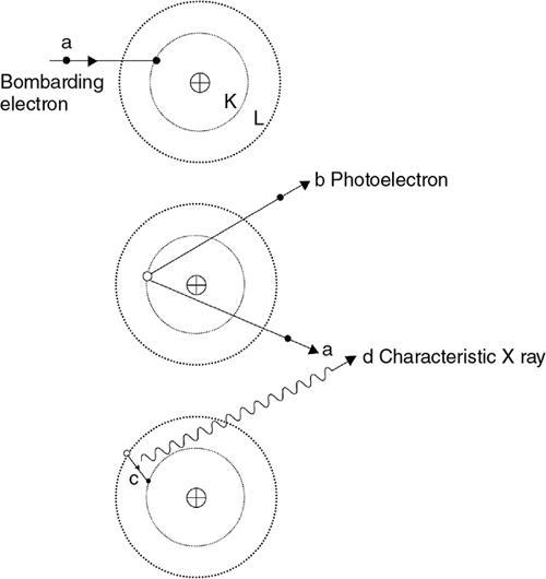
Characteristics Radiation
Bremsstrahlung Radiation
Accounts for a small percent of X-ray photons in the X-ray spectrum
Accounts for about 80% of the total X-ray beam
The interaction of electrons is with inner shell of atom
The interaction of electrons is with the entire atom and nucleus of the atom
The X-ray photons released are from the electron moving in and out the valence shells
The X-ray photons are produced from the deflection of electrons and secondary to binding forces of nucleus
The radiation thus released is of specific energy making line spectrum
The radiation thus produced is made of varying energies and is continuous spectrum
X-ray beam energy depends upon the anode element atomic number independent of the voltage applied across the X-ray tube
X-ray beam energy depends upon the tube voltage applied across the X-ray tube
Related posts:


Stay updated, free articles. Join our Telegram channel

Full access? Get Clinical Tree


