Chapter 8 Radiotherapy beam production
Kilovoltage x-ray beam machines
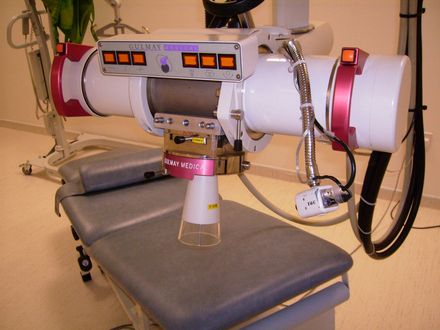
Deep x-ray and superficial units provide x-ray beams in the keV energy range. The term orthovoltage is also used and this term reflects the arrangement whereby the x-rays are produced in a direction at right angles to that of the accelerating voltage. The units typically take the form of a tube assembly which can be manually manipulated to direct the beam onto the patient. The source to surface distance is typically in the range of 20 to 50 cm and the field is defined at the surface by a mechanical applicator. An example of such a machine is shown in Figure 8.1.
Tube stand
The tube is mounted on a mechanism commonly referred to as the tube stand (Figure 8.2). The design of the tube stand enables manipulation of the beam direction by the machine operator in order to direct it at the patient’s lesion. There are both floor mounted and ceiling mounted stands. The design allows translational and rotational movement of the beam and there may be scales of distance and angle which enable the set-up position or changes to it to be recorded and monitored. Electrical or mechanical brakes are fitted to the rotational axes and translational runners in order that the position can be reliably fixed in position prior to treatment and monitored during treatment.
High voltage circuits
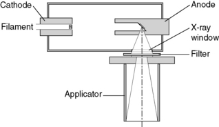
The intensity of the x-ray beam produced at a particular kilovoltage depends upon the number of electrons emitted from the filament, this tube current is a function of the filament temperature and hence the filament current. The filament drive voltage is controlled electronically to respond to changes in the AC supply and stabilize the beam current. A schematic is shown in Figure 8.3. Typically, for voltages in excess of 200 kV, two high voltage power supplies are used in series.

Collimation
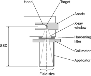
The anode construction provides the initial collimation of the beam as the x-rays come off the target almost omnidirectionally (Figure 8.4). This is referred to as a hooded anode and the aperture defines the maximum size of conical x-ray beam that could be provided. The collimation is completed by use of an applicator which is fixed directly below the tube aperture and provides the following:
• the base of the applicator consists of a collimator which defines the shape and size of the radiation field at the end of the applicator
• the end of the applicator is the shape and size of the radiation beam
• the end of the applicator determines a fixed distance from the source
• the axis of the applicator is mechanically aligned to the axis of the radiation beam.
Skin and eye shielding
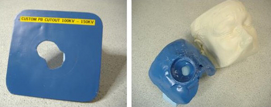
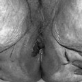
Beam collimation is provided on orthovoltage machines with a range applicators which have regular field sizes. These applicators are usually chosen by the user when the unit is purchased. The choice is made to provide a nominal range of sizes for coverage of typical lesions. Often, it is necessary to treat lesions of non-standard size and irregular shape. It is common practice to manufacture a lead cut-out to define the treatment field exactly to the area specified by the radiotherapist. The cut-out is used in conjunction with one of the regular sized applicators to irradiate the treatment area and shield the surrounding normal skin from the rest of the beam. For lesions on the face and in close proximity to the eyes, a lead mask is manufactured based upon a plaster cast of the patient. As well as defining the treatment field and shielding the normal skin and the eyes, the lead mask can also be used to provide direction and localization of the beam (Figure 8.5).
Megavoltage linear accelerator machines
General layout and components
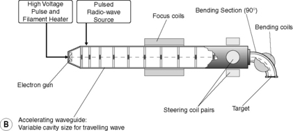
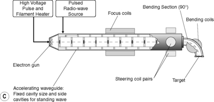
Figure 8.6 illustrates the typical layout of the major components of a linear accelerator.
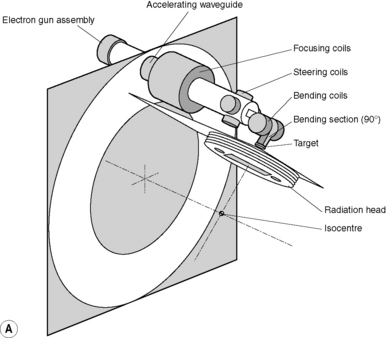
The gantry construction of the standard medical linear accelerator is referred to as being isocentric. In effect, this means that all the main axes of rotation concerning the gantry, the radiation head and the patient couch intersect approximately though the same point in space referred to as the isocentre This is illustrated in Figure 8.7


Stay updated, free articles. Join our Telegram channel

Full access? Get Clinical Tree


