Chapter 33 Radiotherapy simulators
33.1 Aim
The aim of this chapter is to provide the reader with an overview of the similarities and differences between the radiotherapy simulator and the linear accelerator.
33.3 Simulator specifications
• It should be mechanically and geometrically as compatible with as many of the department’s treatment units as possible.
• It should be well constructed so that the manufacturer’s tolerances are maintained for long periods during routine use.
• The variable focus to film distance (FFD) should match the focus to skin distance (FSD) range of the treatment equipment and techniques available.
• As some treatment techniques use very large treatment fields, the image intensifier should have provision to accept or support cassettes of size that will record these fields.
• It should be Digital Imaging and Communications in Medicine (DICOM) compatible to permit digital communication between it and other imaging equipment in the department.
33.4 Gantry design
A conventional standard simulator as described here is found in all radiotherapy departments. (Computed tomography simulators are available, but are not in widespread use.)
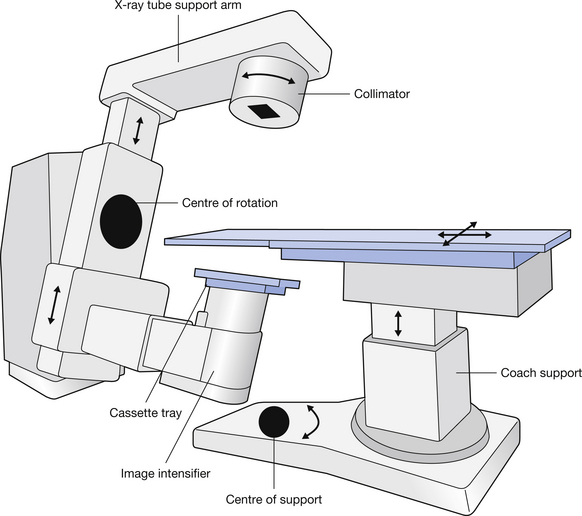
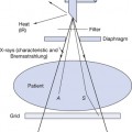
The basic configuration of a gantry (a U, L arm) is shown in Figure 33.1. The U arm is mounted on a vertical stand and is capable of variable speed ±180° rotation about its central point to reflect the rotation that may be used on the linear accelerator for treatment. The upper part of the arm supports the X-ray tube and collimator, which is always directed to the centre of the input of the image intensifier. The length of this part of the arm is variable to permit the selection of different FSDs that may be used in treatment. The lower part of the arm which supports the image intensifier it is also capable of vertical movement so that it can be moved as close to the support table as possible, reducing image magnification. A scale mounted at the rotation point of the U arm indicates the position of the gantry as it rotates about the patient couch.
Stay updated, free articles. Join our Telegram channel

Full access? Get Clinical Tree


