Report Writing and Risk Management Strategies in Skeletal Radiology


Report Writing and Risk Management Strategies in Skeletal Radiology


Lindsay J. Rowe

Terry R. Yochum

Chad J. Maola


X rays are like figures in that they are always correct, [but] we may make a mistake in adding up the column of figures and arrive at the wrong answer.

John Nesbit Scott, 1902


GENERAL CONSIDERATIONS

The formulation of reports in clinical practice is a standard method of documenting a patient’s history, examination findings, therapeutic regime, and prognosis. (1) In the practice of skeletal radiology, report writing serves a number of important roles, including (a) providing an accurate means of recording findings for use during comparison with previous or later examinations, (b) serving as documentation in medicolegal circumstances, (c) providing a permanent record in case the radiographs are lost or not immediately available for perusal, (d) offering a means of communication with other practitioners and health professionals, (e) expediting the management regime by providing a summary of important indications and contraindications for therapy, (f) assisting in auditing radiographic quality, and (g) providing a database for retrospective research and data collection. (1,2,3,4,5,6,7,8) Up until the first edition of this text in 1987, there was a distinct lack of material on report writing and little on what would be considered a standard style. (4,9,10,11) Similarly, the art of verbally presenting studies has received little coverage in the literature. (12) Over the past few years there has been increasing scrutiny and numerous publications dealing with aspects of report generation. This increased interest is predominantly aimed at medicolegal risk reduction, which has refocused attention on the whole reporting process. But still the reporting of skeletal studies remains essentially a subjective, personalized procedure, with individuals modifying the report according to their previous training, experience, and needs. The purposes of this chapter are to provide guidelines for the formulation of musculoskeletal imaging reports, review the medicolegal implications of such reports, and summarize risk management strategies.


ENVIRONS AND EQUIPMENT


Reporting Environment

An appropriate environment for performing the interpretation and subsequent reporting is essential. The evaluation of radiographs in circumstances of disruption, noise, or other distractive
elements is more likely to result in misinterpretations and inaccurate, incoherent reports. Preferably, the room in which the report is dictated should be isolated from the clinical setting and in an area where the least amount of disturbance will occur, making it conducive to focused concentration. In addition, the room should have the capability for adequately decreasing external light sources.


Equipment

The standard practice uses view boxes, a hot (bright) light, transcription devices, and computer or file cabinets for report storage. However, with increasing availability of digital radiography and digital personalized archiving communication systems (PACS), high-resolution computer screens and large-capacity processing units are now being employed to view and store the images and reports, eliminating the need for film.


Viewing Boxes

The viewing space should be large enough to hold two 43- by 35-cm (14- by 17-inch) radiographs side by side (two-bank view box) and produce a bright, uniform light. Four viewing areas (four-bank view box) of the same dimensions are preferable and should be placed at a height at which interpretation can be done from a seated position.


Hot Light

An indispensable viewing accessory is a single, 100-W bulb (hot light) with a foot pedal-operated rheostat control and a 16-cm opening for illumination. This is used to highlight all overexposed regions of a film and to aid in the delineation of normal anatomic or lesion details. Films observed in this manner must be removed from the light within 5-8 sec; otherwise, the extreme heat generated by the bulb may permanently deform the film.


Reporting and Transcription

There are various methods by which radiographic findings are compiled and transcribed into the typewritten word. Handwritten reporting may be convenient when the volume is low and the reports are short. Checklist (canned) methods can be employed when repetitive reporting is involved. (1,2) The most frequently used methods involve verbal dictation with or without voicerecognition technology. The system that is adopted depends on the number and complexity of reports, the necessary capital outlay, and the individual.


Storage

Storage of reports and images is an important legal aspect of any practice. In smaller-volume practices, file cabinets can be used to store hard copies of all information. With computerized transcription techniques, hard copies of reports are often stored in file cabinets in conjunction with electronic file (computer) backups. The computer offers the benefit of being a powerful tool for research, audits, and patient care when the clinician uses special-purpose information and evaluation packages. In high-volume settings using digital technology, PACS will allow for the rapid retrieval and visualization of any previously stored images for reports. (3,4) Modern desktop-publishing techniques make it possible to incorporate selected and annotated images as part of the report. (5)


Digital Radiography

Digital radiography has evolved greatly over the last several years, providing several methods of acquiring images digitally. The use of digital imaging has many advantages in the field of radiography and in clinical practice. For the clinician using digital radiography, this process eliminates the need for dark rooms, processor cleaning, chemicals and their disposal, x-ray film, view boxes, storage of films, repeat x-rays (thus reducing the dosage to patients), and postage to have the films mailed for interpretation. Digital images are traditionally observed on a computer monitor and can be transmitted via the Internet for immediate interpretation by a radiologist. Along with the obvious advantages, the declining cost of digital radiography is making the use of this technology a feasible and practical procedure that will soon become the standard in radiology and private clinical practices. Generally, digital techniques fall into one of two categories: direct and computed radiography. Both methods offer almost immediate access to image data and are easily integrated into existing workflow systems, such as PACS.


Direct Radiography.

Direct radiography (DR) generally refers to capturing an image by exposing radiation directly to a thin silicon or amorphous selenium plate made of individual sensing areas. Images are created by first converting the energy to light through a thin cesium iodide coating (the sensor), made of thousands of pixels. It then captures the light and converts the energy into a high-resolution image. Another method of DR creates images by first converting the radiation to light and then capturing the light with a very sensitive charge-coupled device (CCD). Technologically, DR is the method of choice in radiography owing to its low dose, high speed, and superior resolution. Initially, DR may seem to be a costly method of imaging, but when compared with the film-based high-frequency x-ray systems currently used, the long-term cost effectiveness of DR is substantially greater. (Table 15-1).


Computed Radiography.

Computed radiography (CR) is the digital technique most comparable to the traditional film-based procedure. The process exposes a cassette loaded with a CR screen to radiation, which must then be placed into a reader, where it is scanned by laser and transferred into a digital image. Scan times vary but usually take between 15 and 90 sec each. CR is generally referred to as an interim technology because of the way it is handled and the time it takes to scan and then erase each image from the screen. CR plates also have a shelf life and need to be replaced periodically. This method produces quality images, but in most cases they are not as good as direct methods. CR has become popular owing to its cost and ease of integration with existing film-based systems.


Table 15-1 Fifteen-Year Cost Analysis: Film-Based X-Ray Versus Direct Radiography


Film-Based, High-Frequency (100-KHz) X-Ray


Direct Radiography


Purchase


Five-Year Lease


Purchase


Five-Year Lease


Price


$24,900


Price


$32,370


Price


$49,900


Price


$64,870


60 films/wk/15 years @ $1.10 each


51,480


60 films/wk/15 years @ $1.10 each


51,480


Computer upgrades


5,000


Technician @ $13.00/hr, 3 min/film; developing @ $0.65 each


30,420


Technician @ $13.00/hr, 3 min/film; developing @ $0.65 each


30,420


100 monthly processor cleanings @ $180.00 each


18,000


100 monthly processor cleanings @ $180.00 each


18,000


6 processor repairs


6,000


6 processor repairs


6,000


1 replaced processor


3,600


1 replaced processor


3,600


Total


$130,400


Total


$137,870


Total


$49,000


Total


$69,870


PLAIN FILM PLACEMENT AND ORIENTATION FOR INTERPRETATION

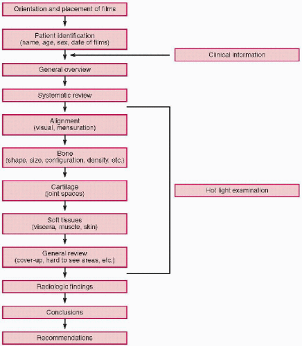
The placement of radiographs on the viewing area should be done in a standardized procedure. By following a systematic routine in placement and orientation, abnormalities will be more readily identified. (1,2,3,4) This is the first step in the interpretation and reporting sequence. (Fig. 15-1)


Spine

Wherever possible all available films of the same spinal region should be viewed simultaneously, with anteroposterior (AP) and lateral side by side, followed by obliques, and then functional studies (flexion-extension).


AP.

There is a divergence of opinion as to how AP spinal films should be oriented on the view box. The orthodox method is to place the films as if the patient were being observed from the front, so that the patient’s right lies on the observer’s left. Other practitioners, especially those involved primarily in the therapy and examination of spine-related complaints, find that films placed as if the patient were being observed from the back are much more practical, so that the patient’s right is on the observer’s right.


Lateral.

Lateral films are best placed as the patient was positioned when the film was taken. A left lateral view should have the apex of a cervical or lumbar lordosis oriented toward the observer’s right side. A left marker means that the film was taken with the left side of the patient against the cassette.


Obliques.

Preferably, all oblique studies should be placed side to side, for better comparison. It is optimal to place the oblique that shows right-sided structures on the left; therefore, in the cervical spine the right anterior oblique or left posterior oblique should be placed on the left of the interpreter. In the lumbar spine the right posterior and left anterior oblique should be placed on the right side.


Dynamic Views.

Placement of dynamic views should be orientated the same as the neutral projection and on the appropriate sides to show the extremes of movement. For example, a left lateral study of the cervical spine should have a flexion view placed to the right and the extension to the left of the neutral view.


Extremities

Preferably all films of the extremities should be viewed simultaneously and generally placed as if viewing the patient from the front. The only exceptions are the hands, wrists, feet, and ankles, which are placed as if looking at the dorsal surface. In addition, films of the hand, wrist, and feet are placed with the digits pointing upward.


Chest

The frontal chest projection should be placed to the left of the lateral study and both films should be viewed simultaneously.


Posteroanterior.

Posteroanterior (PA) views are always placed on the view box as if observing the patient from the front. This places the heart to the right of the observer.


Lateral.

As with lateral spinal films, lateral chest films are oriented based on patient positioning. The routine procedure in positioning the patient is for a left lateral projection, so that the apex of the thoracic kyphosis would be toward the viewer’s left side during interpretation.


Abdomen

Placement of AP abdominal films is as if the patient were being observed from the front; thus, the liver is to the left side of the observer.


Additional Collimated (Spot) Views

For comparison purposes, spot views should be placed alongside the larger film that first delineated the questionable area. Whenever possible, these should be visible simultaneously for proper evaluation.


Comparison Studies

When comparison studies of the same area are available, it is preferable to observe the current films first and isolate any films containing areas of abnormality. Subsequently, a sequential retrospective evaluation based on the dates of the films is done, from the more recent to the oldest studies. In these circumstances it may be preferable to make handwritten notes, correlating the dates with the observed changes, before composing the report.


Figure 15-1 REPORTING FLOW CHART.


REPORT STRUCTURE AND CONTENT

The structure of the report is an especially personalized procedure; however, there are some basic features that should be included. (1,2) (Table 15-2) Interpretation of the radiographs requires extensive skill and the use of appropriate terminology. The development of an interpretation methodology (search pattern) is recommended, so as not to overlook pertinent findings. With repetition the process becomes more rapid and the clinician becomes increasingly more accurate in identifying abnormalities.


Preliminary Information


Stationery.

Information in the letterhead should include the name and address of the clinic or individual who is creating the report.


Report Date.

The date the report is made should be near the top of the page.


Table 15-2 Essentials of Plain-Film Musculoskeletal Reporting


Preliminary information


Letterhead information


Date of report formulation


Name and address of referring clinician


Patient information


Full name


Address


Date of birth


Sex


File identification


Examinations performed


Views submitted


Dates and location of films taken


Clinical information


Chief complaint


Key clinical findings


Reason for study


Numbered summary of pertinent clinical findings, if complex


Report


Technical factors (kilovoltage, milliamperes, tube-film distance, etc.)—optional


Radiologic findings


Descriptive narrative of findings (ABCs)


Conclusions


Succinct summary of diagnoses


Recommendations


Additional imaging and/or management


Indications and contraindications to treatment


Follow-up procedures indicated


Signature and qualifications


Referring Clinician’s Information.

If the report is for another clinician, his or her name and address should be placed near the top of the report.


Patient Demographics.

The patient’s full name, address, date of birth, sex, and file number should be given.


Examination Information.

All views that are being submitted for evaluation should be listed, view-by-view, for each anatomic location. Additional information that must be listed here is the location and dates the films were taken. If there is inadequate or unreadable identification, this also should be stated.


Clinical History.

Selected important aspects of the presenting complaint, past history, physical examination, laboratory results, and findings from previous examinations should be listed. (3) These details aid the examiner in interpretation because they direct attention to an area for more careful scrutiny and observation and assist in excluding uninvolved structures. (4) Failure to integrate an adequate clinical history and findings diminishes diagnostic accuracy. (5,6) When possible, any abnormality should be related back to the patient’s clinical symptoms.


The Report

The report itself is divided into three distinct sections: radiologic findings, conclusions, and recommendations. An optional section may be used to convey technological information.


Technical Information

Inclusion of technical information in the report is optional. Data concerning peak kilovoltage (kVp), milliamperes (mAs), tube-film distance, bucky versus non-bucky, screen type, and gonadalshielding application can be useful, especially if one considers a later re-evaluation. This part of the report can also be used to calculate the skin radiation dose to the patient. All this information should be kept in an accessible location, even if not part of the final report.


Radiologic Findings

Before beginning to interpret radiographs, it is useful to allow approximately 5 min for light adaptation to occur. Also, while evaluating films, unused view box space is turned off, to reduce unnecessary glare or eyestrain and to improve the ability to detect subtle lesions. (7) It is in this section of the report that the descriptive narration containing the report of findings is made.

Chapter 7 provides guidelines for appropriate terminology for describing various abnormalities. Correct use of terms and an ordered sequence of reporting are essential for accuracy and clarity. (1,8,9,10,11,12) (Table 15-3) This is achieved by means of a systematic method of observation along with the possession of the necessary background in normal radiographic anatomy and signs of disease. (13,14,15) Most pathologies that are overlooked are missed because of lack of attention to a step-by-step sequential evaluation of normal anatomy and correlation with the pertinent clinical data. (9,16,17,18) (Fig. 15-1)


General Overview.

Make an initial overview of the studies, looking for anything obvious that catches the eye and correlating it on other views. Following this initial inspection for each film, read the identification nameplate, confirming the patient’s name
and other demographics. Then identify what projection each film represents. At this stage it is vital to assess each film for technical quality, including exposure, collimation, positioning, motion, phase of respiration, applied markers (erect, supine, right-left, etc.), and artifacts.


Table 15-3 Summary of Key Terms for Reporting Musculoskeletal Disease


Biomechanical


Fixation, hypomobility, hypermobility


Instability


Misalignment


Congenital


Hypoplasia, hyperplasia, dysplasia


Underdeveloped, overdeveloped, maldevelopment


Agenesis


Trauma


Fracture: transverse, oblique, spiral, avulsion, pathologic


Comminution


Apposition, angulation, displacement, intra-articular


Subluxation, dislocation


Non-union, malunion


Callus


Neoplastic


Bone destruction: geographic, moth-eaten, permeative


Position: centric, eccentric


Periostitis: solid, laminated, spiculated


Zone of transition: wide, narrow


Cortical integrity: intact, disrupted, expanded


Matrix: fibrous, cartilage, osteoid, bone


Soft tissue mass


Location: diaphysis, metaphysis, epiphysis


Distribution: monostotic, polyostotic


Arthritides


Joint space loss: uniform, non-uniform, ankylosis, chondrocalcinosis


Subchondral bone changes: sclerosis, cysts, osteopenia


Joint erosions: extra-articular, marginal


Bony outgrowths: osteophytes, syndesmophytes, hyperostosis


Periostitis: linear, irregular


Enthesopathy: erosions, periostitis


Soft tissue depositions: extra-articular, intra-articular


Malalignments: subluxations, deformities


Nutritional, metabolic, endocrine


Osteopenia: osteoporosis, osteomalacia


Cortical changes: thinning, thickening, erosion


Trabecular changes: loss, accentuation, thickening


Soft tissue calcification


Infection


Bone destruction: geographic, moth-eaten, sequestrum


Periostitis: solid, laminated (involucrum), Codman’s triangle


Cortex: thickening, destruction (cloaca)


Articular cortex: preservation, destruction


Soft tissue planes: displaced, blurred, obliterated


Systematic Review.

The sequence by which the structures are evaluated depends on what best suits the individual and will frequently vary according to findings. However, adopting a standardized procedure will assist in performing a thorough review of the study. Furthermore, when verbalizing findings over the telephone or presenting a case to other clinicians, such guidelines will provide a more organized discussion of the findings. We have proposed, since the first edition of this text in 1987, the mnemonic ABCs as a guide to an ordered, sequential evaluation, which many have found useful. ABCs stands for alignment, bone, cartilage, and soft tissue. It is important that a flexible use of this approach be adopted, which may be modified depending on a particular case. When a site of abnormality is identified, it should be described completely, which again can be done with the ABCs approach. Once this is completed, then the search can be continued to other areas.


Alignment.

The first aspect reviewed is the alignment of the skeletal structures. Application of the various mensuration procedures will assist in this part of the evaluation.

In the spine, aspects of spinal curvature, rotation, and other interosseous disrelationships are noted. This part of the examination applies both to static and functional stress studies. Lordotic and kyphotic contours should be assessed in regard to the amount, type, and configuration of the curvature. Using measurement parameters and normal ranges, the investigator can designate the curvatures as hyper, hypo, or normal. (See Chapter 2.) Underlying causes for an altered curve should also be identified.

Scolioses need to be carefully evaluated. (See Chapter 4.) The type of curve should be described (e.g., C, S shape, compensated, uncompensated). The degree of curvature must be measured (Cobb’s method). The side to which the convexity occurs, the identification of the apical segment, and the degree of rotation within the curve should also be noted. A search for an underlying cause must always be made.

Intersegmental spinal misalignments are common and need to be reported judiciously and in a clinical context. Terminology for vertebral misalignments has been standardized. (19) Designation of the spatial orientation of one vertebra in relation to adjacent segments is called a listing. This would include flexion, extension, lateral flexion, rotation, anterolisthesis, retrolisthesis, and laterolisthesis. Spondylolisthesis should be assessed by Meyerding’s classification as to the grade of slippage or a percentage of slippage. (20) (See Chapter 5.)

In the extremities, relationships of bony components across joints or at fracture sites are integral parts of all radiographic reports. The hand afflicted with rheumatoid arthritis may show a number of misalignments, including ulnar deviation, boutonniere deformities, and zigzag deformities. A full description of a fracture includes a statement about the location, direction, and nature of the fracture line as well as aspects of alignment such as apposition, angulation, and rotation. (21,22) At the hip joint, alignment can be made visually by the continuity of Shenton’s and iliofemoral lines. (See Chapter 2.)


Bone.

Next, details of the visualized osseous structures are observed. This includes scrutiny of the cortices; medullary trabecular patterns; general density; and the size, shape, and configuration of all bones. In the spine, the key bony landmarks are the vertebral body endplates; vertebral body trabeculae; pedicles; and transverse, spinous, and articular processes. If no osseous abnormality is found, then an appropriate sentence stating this negative finding can be made. For example, if the clinical concern was the presence of fracture that has not been confirmed, then a statement such as “no fracture or dislocation is evident” may suffice. Similarly, the absence of suspected neoplasia could be denoted as “no osseous neoplastic change is radiographically apparent.” A generic statement relating that no bony abnormality is present could be “no osseous abnormality has been demonstrated.”


Cartilage.

Normally, cartilage is not visible on radiographs but instead is manifested by the radiographic joint space. This C part of the mnemonic is to remind the observer to look carefully at all joints displayed. In the spine, the joints include the intervertebral
disc spaces and the apophyseal, atlantoaxial, neurocentral, and costovertebral articulations. The peripheral joints are readily recognized. Each joint can be assessed for the depth of the joint space, the smooth articular bony cortex, and the bone density beneath the cortex (subchondral bone). The width of the joint cavity reflects the cartilage thickness, with only the small loose joints of the toes or fingers widening owing to effusion. Narrowing of the joint space reflects loss of the articular cartilage and is a sign of arthritis. The articular cortex is thin but is usually clear and sharp in its outline and smooth in contour. Loss of the joint cortex is a key sign of articular disease and may be the result of synovial proliferation, infection, or degenerative synovial cyst (geode). Thickening of the joint cortex can be seen with degenerative joint disease. When reporting about a joint, comments on these features should be made; for a normal joint a relevant statement would be “the joint space is preserved, the articular surfaces are smooth and congruent and of normal density” or “there is no joint abnormality.”


Soft Tissue.

Although soft tissues may provide many important signs of disease, it is the most commonly overlooked feature on a musculoskeletal radiograph, CT scan, and even MRI study. The visibility of a soft tissue structure predominantly depends on its density, tissue type, and often the presence of encapsulating fat. Skin line displacement can be helpful in identifying a mass or edema. In the extremities, the interspaced fat in the fascial planes can identify the individual muscle bellies; on plain films, the best examples are the pronator quadratus on the lateral wrist view and the supinator fat line on a lateral elbow projection. In the spine, the psoas muscle outline is a key structure, as is the prevertebral soft tissue in the neck. Displaced pericapsular fat in the elbow can be a sign of joint effusion. Additional signs to be searched for include loss of the fascial plane fat, a sign of edema, and displacement of the same fat lines, a sign of adjacent mass and calcification. Perusal of all soft tissues included on the film should be performed. The presence of calcium in abnormalities such as gallbladder and renal calculi, aneurysms of the aorta, and cysts can be diagnostic.


Supplementary Review.

On completion of the sequential ABCs, a supplemental review must be performed. A number of methods have been proposed by various individuals in an attempt to minimize the possibility of overlooking subtle abnormalities.


  • Review of hard-to-see areas. On any radiograph there are always details that are usually obscured and difficult to visualize because of anatomic superimposition or because of the projection. Therefore, if an abnormality is present in one of these obscured areas, it is likely to be overlooked without careful scrutiny. (23) This includes those portions of the film that are inherently overexposed or covered by another anatomic structure, such as the view box holding clip, positioning markers, identification plate, and any other obscuring artifact. (Table 15-4)


  • Hot (bright) light examination. No interpretation is complete without each radiograph being illuminated by the hot light. Examination by this method is especially useful in overexposed areas that are not normally rendered visible on the ordinary view box. In addition, by limiting the field of view, closer inspection of individual details is enhanced. (7,24)


  • Cover-up examination. This is a useful technique for larger-size radiographs, but it can also be applied to any film. The basic idea is to limit the field of view to a small area, inspect it, and move to another portion of the radiograph. The larger the surface area available to be inspected, the more anatomic details that must be examined. A simple way to reduce the observable area is to take a 45- by 37-cm (14- by 17-inch) film envelope, cover the entire film up, and slowly move the envelope down while observing the limited view of the film. In addition to limiting the field, the interpreter’s eyes are forced to compare one side with the other, carefully noting individual details. The combination of reduced visual field and augmented visual acuity makes this a useful review method.


    Table 15-4 Hard-to-See Review Areas


    Cervical spine


    Skull base


    Odontoid process


    Neurocentral joints


    Cervicothoracic junction


    Prevertebral soft tissues


    Trachea


    Lung apices


    Thoracic spine


    Pedicles


    Posterior ribs


    Paravertebral lines


    Posterior lung fields


    Diaphragms


    Posterior costophrenic sulcus


    Costotransverse joints


    Lumbar spine


    Apophyseal joints


    Pedicles


    Pars interarticularis


    Lung bases


    Lower ribs and costal joints


    Gas patterns


    Psoas


    Pelvis and hips


    Acetabular floor


    Iliac crest


    Sacral foramina


    Sacroiliac joints


    Femoral head and neck


    Knee


    Patellofemoral joint


    Intercondylar notch


    Tibial eminences


    Tibial tuberosity


    Hoffa’s fat-pad


    Ankle


    Malleoli (3)


    Talar dome


    Anterior process of calcaneus


    Cuneiforms, cuboid


    Subtalar joint


    Foot


    Phalanges


    Metatarsal heads


    Hallux sesamoids


    Shoulder


    Lung apex


    Greater tuberosity


    Coracoid and acromion process


    Elbow


    Fat-pad positions


    Radial tuberosity


    Olecranon, coronoid fossae


    Supinator fat line


    Wrist


    Scaphoid waist


    Scapholunate interspace


    Hook of the hamate


    Ulnar variance


    Triangular fibrocartilage


    Metacarpotrapezial joint


    Hand


    Distal phalanx


    Metacarpal heads


    Metacarpocarpal joints (4,5)


  • Other examinations. Many other methods have been proposed by individuals to enhance visual perception, most of which were “discovered” by personal experience. These methods range from scientific attempts to enhance eye physiology to simple cheating (discussed below). (18)


Fingerprints.

One of the simplest “cheating” methods is Hartley’s (25) fingerprint method. This requires pulling the film off the view box, tilting the radiograph at such an angle that the film surface shines, and looking for fingerprints. The presence of fingerprints in a particular area may disclose an abnormality as a result of the film being previously viewed and the observer’s finger pointing out a subtle pathology. Obviously, films do not come out of the processor with accurately placed fingerprints!


Film Tilt.

Tilting the film can sometimes be useful because it reduces the field of vision. This is particularly applicable to evaluation of the spinal pedicles, a common site for aggressive neoplastic disease. By slightly tilting a lumbar or thoracic film away from the observer, visual inspection of the pedicle cortices is enhanced, allowing easier comparison with adjacent segments. Almost any structure can be evaluated by this tilt method. Also, for traditional films that use two-sided emulsion film, tilt will enhance the parallax differences of each side and may enhance anatomy and any pathologic change.


Magnification.

Some have advocated the use of different magnifying devices, most commonly the simple, hand-held lens. This obviously has its greatest advantage when observing fine, individual details, but not during the overall evaluation. Once a questionable area has been isolated, the use of a magnifying glass can help further delineate the characteristics of a possible pathology. Digitized images are readily enlarged by means of computer technology.


Odontoid Identification.

One of the more difficult structures to identify is the odontoid process, yet it is a common area of abnormality. A useful method to aid in the scrutiny of this structure is to place a fingertip over the area as closely as possible to where it would be expected to be located. (26) Identification of the atlas anterior tubercle will aid in the correct placement of the finger. Once in place, careful observation of the finger outline is performed and the finger is subsequently removed from the film. Continued attention to the region will often allow the outline of the odontoid to be identified because the size and shape of the finger is quite similar.


Cupped Hand.

For increased visual acuity, especially in group circumstances, observing through a cupped hand will additionally reduce unnecessary glare. (27) This cupped hand method also enables those who are myopic to enhance their visual range and acuity.


Summarization of Findings.

Before developing statements for the conclusion, it is important to summarize and synthesize the findings relevant for formulating diagnoses and relative priorities.


Conclusions

Many radiologists use the term impression to label the conclusion section of the report; however, the word conclusion is currently the preferred term because it commits the author to succinctly summarize with deductive reasoning the meaning of the described findings and to convey to the clinician their importance. (4) Remember that < 40% of reports are read in full by the treating clinician, with the majority of clinicians focusing only on the conclusion—this stresses the importance of the conclusion section. (28) A point-by-point summary of diagnoses is the desired format. The purpose is to list the most important radiologic findings and diagnoses based on the previous narrative descriptions. These should be short, concise statements using standard and precise terminology. (1,29) Listing of a few selected differential considerations can be useful, but there should be avoidance of long lists.


Recommendations

A short statement or number of statements can be made following the conclusions for the purpose of directing attention to a particularly significant finding or diagnosis. This is an optional component of the report and can be employed at the discretion of the author. This part of the report may address therapeutic implications, contraindications to specific therapies, or suggestions for further evaluation as deemed appropriate. At the end of the report, authors should ascribe their names and qualifications and then add their signature nearby.


REPORT VARIATIONS FOR CT AND MRI

Owing to the inherently more complex modes of image acquisition, a greater number of technical variables and the greater amount of available diagnostic information, CT and MRI reports have to be tailored differently. (1,2)


Computed Tomography


Identification of Images and Information

Significant variations in the format of image display are common, depending on the CT unit and the facility. Despite this, the relevant information provided remains essentially the same. It is recommended to locate the following images and information, before orienting and interpreting the films.


Information Block.

Locate the film that is displaying the information on the patient and examination technique. This usually is identifiable as the section that has no anatomic images and instead lists the patient’s name, age, clinically relevant data, referring doctor, suspected clinical diagnosis, and examination parameters (e.g., the number of scans and if contrast was used).


Scout Images.

A digitally processed frontal or lateral view of the body part being imaged is next identified. On the scout image, lines may or may not be visible representing the site where images were programmed to be obtained. When present, this information is known as the scan selection technique. From this, one may then derive the end points of the examination, the number of images taken, the distance intervals between images, gantry (tube) angulation, and areas of interest. Each slice is usually numbered but often not readily decipherable.

Only gold members can continue reading. Log In or Register to continue

Stay updated, free articles. Join our Telegram channel

Aug 2, 2016 | Posted by in GENERAL RADIOLOGY | Comments Off on Report Writing and Risk Management Strategies in Skeletal Radiology

Full access? Get Clinical Tree
Get Clinical Tree app for offline access