Fig. 9b.1
Optimal positioning of the ECG electrodes on the chest. Panel A shows the IEC standard and Panel B: the USA standard
Details of patient preparation for coronary CT angiography on all scanner types are presented in Chaps. 7 and 9.
9.2 Image Acquisition
Acquisition of a conventional chest topogram (Fig. 9b.2) may be followed by planning and acquiring two axial control scans (Fig. 9b.3). The first control scan is acquired in the plane with the largest transverse extension of the heart and serves to optimize the field of view for the subsequent CT angiogram (Fig. 9b.3). Bi-plane topograms in the anteroposterior and lateral projections allow adjustment of the table height to make sure that the patient’s heart is positioned in the center of the gantry, where the spatial and temporal resolution in the image are highest.
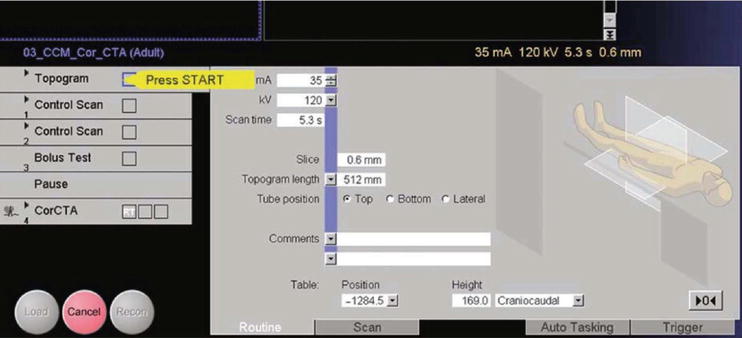
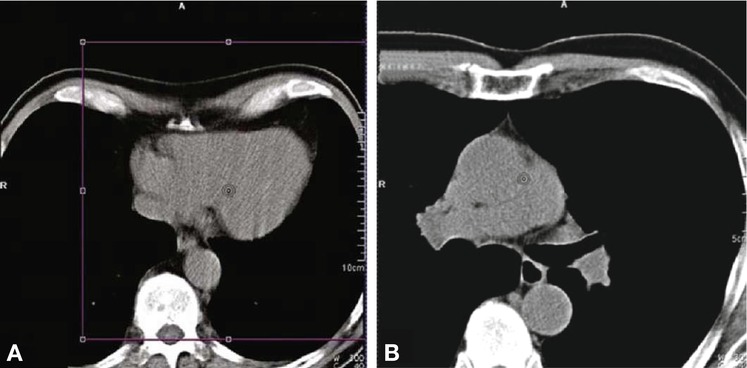
Fig. 9b.2
The first step is the acquisition of a chest topogram (scanogram), typically acquired from top to bottom. To minimize the scan area, the acquisition can be stopped as soon as the entire heart has been scanned
Fig. 9b.3
Acquisition of two control scans. The first control scan (Panel A) is positioned at the level of the greatest transverse extension of the cardiac silhouette on the topogram and serves to plan the field of view “violet box” for the coronary CT angiography scan. The second control scan (Panel B) is obtained about 1–2 cm below the tracheal bifurcation to identify the position for test bolus acquisition
The second control scan is obtained to select the scan position for test bolus acquisition (Fig. 9b.3). The subsequent test bolus scan consists of a series of images acquired at a rate of one image every 1–2 s (Fig. 9b.4). The test bolus consists of 10–15 ml of iodine-based contrast medium, followed by a 30–50-ml saline flush (injection rate: 5 ml s−1) in normal-weight patients. Radiation exposure is minimized by starting the scan 10–15 s after injection and stopping acquisition once the contrast medium peak has been reached. A dedicated software tool, DynEva, is available for semiautomatic analysis of the test bolus series. The scan delay (the time interval between the start of the test bolus injection and image acquisition) is calculated as the individual test bolus arrival time plus an additional 3 s. The additional 3 s delay is necessary to achieve optimal arterial contrast in the ascending aorta and the coronary arteries while ensuring low contrast in the right ventricle and the right atrium in order to avoid inflow artifacts, which may hamper the evaluation of the right coronary artery.
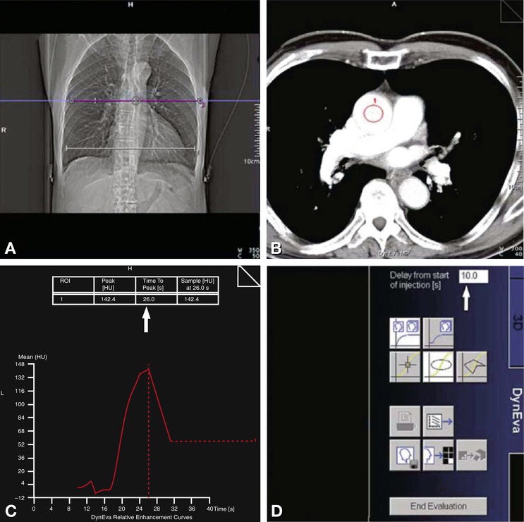
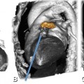
Fig. 9b.4
Bolus test scan. The test scan (redline in Panel A) comprises a maximum of 40 images. It is started 10–15 s after the beginning of the contrast medium injection. The test bolus series can be analyzed visually or with the DynEva software (Panels B–D). A region of interest (ROI) is defined in the ascending aorta for analysis (Panel B). The time to peak can be read in a table (arrow in Panel C) after entering the delay used for image acquisition (arrow in Panel D)
Alternatively, all current Siemens CT systems have contrast bolus tracking software, used as the preferred option in many centers. A reference image is acquired at the level of the aortic root. A region of interest is then placed within the aorta. Repetitive scans are acquired at the same level to follow the arrival of the contrast medium. The consecutive cardiac scan is initiated once enhancement surpasses a predefined threshold in the ascending aorta.
Next, the CT angiography scan, planned to cover the entire heart is acquired from top to bottom (Fig. 9b.5). To minimize the inferior extension of the scan field, scanning can be manually discontinued as soon as the real-time images show the entire heart.
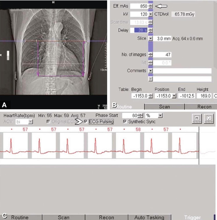
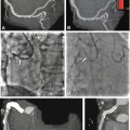
Fig. 9b.5
Planning of the coronary CT angiography scan (Panel A). For normal-weight patients, the manufacturer recommends 850 eff. mAs (arrow in Panel B). In slender patients, radiation exposure can be considerably reduced by using a 100 kV protocol. The highest possible eff. mAs value may be required in obese patients. Finally, prospective ECG dose modulation (ECG pulsing) can be activated from the trigger card of the Syngo menu (arrowhead in Panel C)
With a single-source Somatom Sensation scanner, prospective ECG dose modulation (ECG pulsing) should be used for all retrospectively gated spiral scans in patients with a regular sinus rhythm, as it can reduce radiation exposure by up to 40–50%. In slender patients, radiation exposure is furthermore reduced considerably by using a 100 kVp or even 80 kVp scan protocol. Recent CT systems from Siemens are equipped with an automated exposure control (“CAREkV”) for adjusting both tube current and voltage to the patient’s body habitus. This tool uses reference imaging parameters (kVp and mAs) for the desired contrast-to-noise ratio. These adjustments can be refined further by specifying the tissue of interest (e.g., vasculature in the case of cardiac CT), optimizing acquisition parameters for CT angiography, or aiming at lower X-ray tube voltage with high signal-to-noise ratio (Fig. 9b.6).
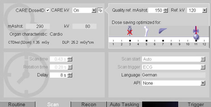
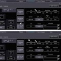
Fig. 9b.6
Based on quality reference mAs and kVp the effective imaging parameters are calculated according to the intended investigation (CTA selected by the slider on the right, arrow) and the body habitus of the patient. In this example exposure was set to 290 mAs with 80 kVp, resulting in a CTDI and DLP of 1,35 mGy and DLP of 25,2 mGy · cm for a high-pitch spiral CT scan
9.3 Image Reconstruction
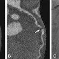
The first step in image reconstruction is to check the recorded ECG (Fig. 9b.7). If there are isolated extrasystoles, the corresponding reconstruction intervals can be deactivated or deleted for image reconstruction. It is recommended to generated a preview series based on a reference image at the level of the mid-RCA (segment 2) to identify the most suitable phase for image reconstruction (Fig. 9b.8). Next, thin-slice data sets (0.6–0.75 mm) are reconstructed at the optimal phase of the RR interval determined in this way (Fig. 9b.9).
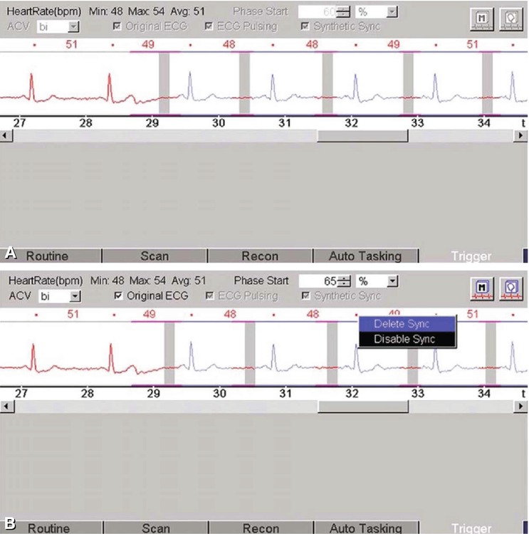
Fig. 9b.7


Related posts:
Stay updated, free articles. Join our Telegram channel
Full access? Get Clinical Tree
