Marcia F. Blacksin, MD
PELVIS
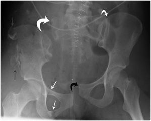
The pelvis is formed by the ischium, the pubic bones, and ilium, which through the sacroiliac joints (SI joints) connect to the sacrum. This forms a ring structure. The pubic bones are joined anteriorly by the pubic symphysis and form the anterior ring. The posterior ring is formed by the sacrum, the SI joints, and iliac bones. To disrupt this ring usually requires significant force, which can occur in motor vehicle accidents or similar high-energy trauma. A ring structure usually breaks in more than one place, so it is important to carefully examine the entire ring for a second injury once a fracture is encountered. The second injury does not need to be a fracture; it can be disruption of the SI joints or pubic symphysis (Figure 3-1).
Figure 3-1. Open book injury. There is marked widening of the right SI joint (curved large white arrow) and disruption of the pubic symphysis (curved small black arrow). The right hemipelvis is inferiorly displaced. The left SI joint is disrupted (curved small white arrow). There is a comminuted fracture of the right iliac wing (gray arrow), and there are fractures of both pubic rami (white arrows), as the obturator ring in itself comprises a ring structure.
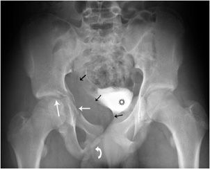
For diagnosing acetabular fractures (Figure 3-2), it is important to differentiate between the acetabular wall, column, or a combination of wall and column fractures. In short, the anterior column extends from the iliac crest to the symphysis pubis and includes the anterior wall. The posterior column extends from the superior gluteal notch to the ischial tuberosity and includes the posterior wall. The acetabular roof is the superior weight-bearing portion of the acetabulum and contributes to the anterior and posterior column.1–3 For adequate radiographic assessment, bilaterally angled oblique views, so-called “Judet views,” are obtained in addition to the standard AP radiograph because the anterior and posterior columns are better visualized on the Judet views. All acetabular fractures will be evaluated with CT, including cross-sectional reformats, as it provides detailed information about the number, size, and displacement of fracture fragments. Acetabular fractures result from high-energy trauma, such as motor vehicle collisions or a fall from height. The most complex of the acetabular fractures is when both anterior and posterior acetabular columns are involved. Both columns are separated from each other and from the axial skeleton, resulting in a “floating” acetabulum. The spur sign4 seen on an obturator oblique view is diagnostic of both columns being fractured. It is caused by a triangular bone fragment with an inferiorly directed apex.
Figure 3-2. Acetabular fracture. The fracture extends through the posterior wall and the junction of the anterior wall with the superior pubic ramus (white arrows). There is a fracture through the inferior pubic ramus (curved arrow). Therefore, the fracture involves both columns. There is a large pelvic hematoma (black arrows) in the obturator internus muscle, displacing the contrast filled urinary bladder (black star).
HIP
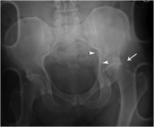
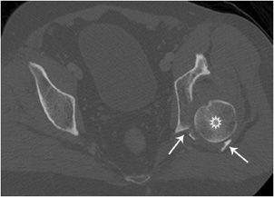
Posterior hip dislocations (Figures 3-3 and 3-4) are frequently caused when the hip and knee are flexed, as in a car accident when the knee strikes against the dashboard. Posterior hip dislocations are much more frequent than anterior hip dislocations. Often there are associated fractures of the posterior acetabular wall and femoral head. Anterior hip dislocations (Figures 3-5 and 3-6) comprise about 10–15% of traumatic hip dislocations. They occur when the hip is abducted and the knee strikes the dashboard, or when the patient is squatting and the back is hit. On radiographs, the affected femoral head may appear larger due to AP magnification and the femur is externally rotated. There may be associated fractures of the femoral head and anterior acetabular wall. After reduction of the hip dislocation, radiographs are performed to assess congruency of the hip joint. A CT is also necessary to evaluate for associated fractures of the femoral head or acetabulum and intra-articular fracture fragments.
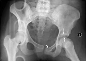
Figure 3-3. Posterior hip dislocation. The left femoral head (white arrow) is posteriorly, superiorly and laterally displaced with respect to the acetabulum. There is an associated fracture of the posterior acetabular wall, extending into the ilium (arrow heads).
Figure 3-4. Posterior hip dislocation (CT). The left femoral head (star) is posteriorly dislocated. The comminuted posterior wall fracture (arrows) is readily identified on CT.
Figure 3-5. Anterior hip dislocation. There is marked left hip joint space widening (arrows). The left femoral head is held in extreme external rotation. There is also disruption of the pubic symphysis (curved arrow).
Figure 3-6. Anterior hip dislocation (CT). The left femoral head (white arrow) does not articulate with the acetabulum (open arrow). The femur is markedly externally rotated, so that the greater trochanter is articulating with the acetabulum.
Femoral neck fractures are described according to the area of the femoral neck that is involved. If the fracture occurred at the junction of the femoral head with the neck, it is called a subcapital fracture. Just distal to the subcapital fracture is the midcervical fracture (Figure 3-7). If the fracture is seen at the base of the neck, it is a basicervical fracture. These three fractures are intracapsular fractures. Since there is disruption of intraosseous cervical vessels responsible for blood supply to the femoral head, the incidence of avascular necrosis (AVN) rises with the degree of fracture displacement and can be around 25%.5 Fracture reduction also plays a role in AVN development. Intertrochanteric fractures (Figure 3-8), which are extracapsular in nature, occur between the greater and lesser trochanter. There is cancellous bone in that region, which is well vascularized and therefore heals well. Intertrochanteric fractures are divided into stable and unstable fractures. A stable fracture demonstrates cortical contact, either initially or after reduction. An unstable fracture has either a large area of posterior medial comminution or a subtrochanteric component. Fractures that occur immediately below the lesser trochanter are termed subtrochanteric fractures.
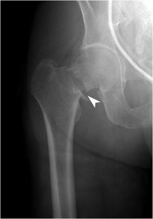
Figure 3-7. Femoral neck fracture. Minimally displaced, slightly distracted midcervical fracture (arrowhead). The fracture is slightly medially impacted, with resultant coxa vara deformity of the hip.
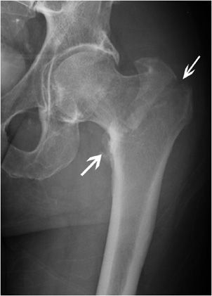
Figure 3-8. Intertrochanteric fracture. Fracture of the intertrochanteric femur extending from the greater to the lesser trochanter (arrows).
FEMUR
Femoral shaft fractures are generally caused by high-energy forces and are often associated with multisystem trauma. The appearance of femoral shaft fractures range from nondisplaced fractures to severely comminuted fractures with significant soft tissue injuries. The femur is well vascularized and significant blood loss can occur, requiring transfusion in up to 40% of isolated fractures.6 Most femoral shaft fractures are treated with intramedullary nails or plate fixation. The goal is to start mobilization as soon as possible, allowing both hip and knee motion and strengthening. Injuries and fractures of the femoral shaft may have significant short- and long-term effects on the hip and knee joints if alignment is not restored. Femoral fracture patterns vary according to the direction and amount of the force. The amount of comminution increases with the amount of energy absorbed by the femur at the time of fracture.
KNEE
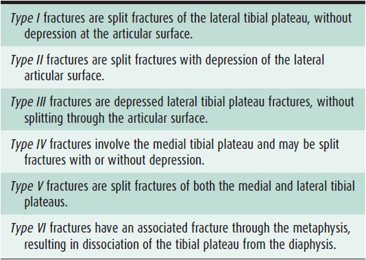
Tibial plateau fractures (Figures 3-9 and 3-10) affect knee alignment, stability, and motion. It is one of the most critical load-bearing areas in the human body. The medial plateau is stronger than the lateral; therefore, lateral plateau fractures are more common. Medial plateau fractures are caused by higher energy trauma and have more associated soft tissue injuries. In younger patients, the most common fracture pattern is a split fracture, while in older, osteoporotic patients, depression fractures are more typical. The Schatzker classification7,8 is the standard classification system for tibial plateau fractures (Table 3-1). Prevalence of ligament injury in tibial plateau fractures is approximately 20–30%. Detection and appropriate treatment of tibial plateau fractures are critical in minimizing patient disability and reducing the risk of complications, especially posttraumatic arthritis.9
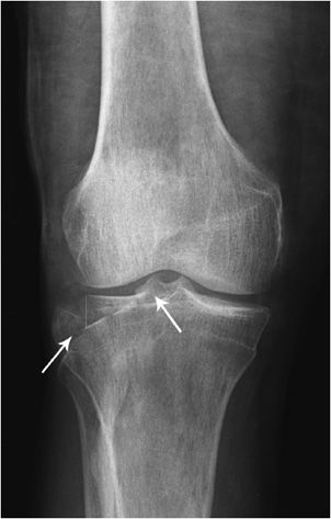
Figure 3-9. Lateral tibial plateau fracture. AP view of the knee demonstrating significant step-off at the articular surface of the lateral tibial plateau (arrows).
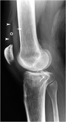
Figure 3-10. Lateral tibial plateau fracture. Lateral view of the knee shows a lateral tibial plateau fracture (arrow), and a lipohemarthrosis (arrowheads) depicting a level between fat (star) and blood in the suprapatellar pouch.
Table 3-1. Schatzker Classification of Tibial Plateau
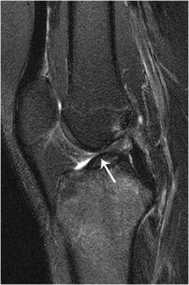
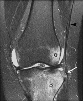
A “Segond fracture” (Figures 3-11 to 3-13) is a small vertical avulsion injury of the lateral aspect of the proximal tibia. It is caused by excessive internal rotation and varus stress. It is associated with detachment of the lateral collateral ligament and tears of the anterior cruciate ligament (Figures 3-11 and 3-12) in excess of 90%.10,11 Often, there are associated injuries of the menisci and other supporting ligaments.
Figure 3-11. Segond fracture. A sliver of bone (arrowheads) has been avulsed from the lateral tibia at Gerdy’s tubercle.
Figure 3-12. Segond fracture. Sagittal proton density fat-suppressed knee MRI showing an ACL tear (arrow).
Figure 3-13. Segond fracture. Coronal fat suppressed T2 weighted MRI demonstrates avulsion of a small bone fragment (white arrow) from the lateral aspect of the tibial plateau by the iliotibial band (black arrowhead). There is extensive bone marrow edema (black stars).
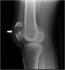
Patella fractures (Figure 3-14) occur most commonly by indirect trauma when the knee is in a semiflexed position and there is sudden contracture of the quadriceps muscle. Displacement or gapping of more than 2–3 mm is significant, requiring operative fixation. If there are small, non-salvageable polar fragments, where the articular surface cannot be restored or stable fixation cannot be achieved, a partial patellectomy is performed. A bipartite patella is not to be mistaken for a fracture; it is a normal variant, representing a nonfused ossification center and always occurs at the superior lateral pole of the patella.
Figure 3-14. Patella fracture. The figure shows comminution of the inferior pole of patella and gapping (arrow) between the distracted fracture fragments.
ANKLE
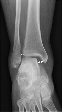
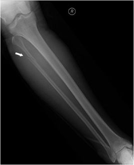
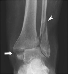
The Maisonneuve (Figures 3-15 and 3-16) fracture12 is easily overlooked on standard ankle radiographs, as it is distant from the area routinely covered. It is a subtype of the Weber type C fracture, where there is a high fracture of the fibula resulting from external rotation and pronation (Weber type A: lateral malleolus fracture is below the level of ankle joint, type B: at the level of ankle joint, type C: above the level of ankle joint). This injury may occur with medial malleolar or posterior malleolar fractures and may have associated ligament injuries, such as the deltoid, anterior talofibular, or posterior tibiofibular ligaments. The interosseous ligament is ruptured to the level of the fibular fracture. It represents an unstable ankle injury. In a trimalleolar fracture (Figures 3-17 and 3-18) also known as “Cotton’s fracture,” the medial, lateral, and posterior lip of the tibia (posterior malleolus) are fractured. When assessing ankle films for fractures, certain areas should be evaluated. The joint space around the talar dome on the mortise view should be approximately equal on all three sides; joint space widening indicates instability. The talocrural angle should be assessed by drawing a line between the tips of the medial and lateral malleoli (intermalleolar line) and a line along the tibial plafond. This angle normally measures 8–15°. Fibular shortening is present when this angle is 2–5°greater than on the opposite side. On the mortise view, the tibiofibular line is formed between the distal tibia and medial fibular cortex. It should be continuous with the lateral cortex of the talar dome. If there is disruption, it indicates shortening, lateral displacement, and external rotation of the fibula. On a normal AP view, the distal tibia and fibula overlap 1 cm, while less than 1 cm indicates syndesmotic injury.
Figure 3-15. Maisonneuve fracture. Ankle, mortise view, demonstrating widening of the medial gutter of the ankle mortise (double-headed arrow) and mild widening of the syndesmosis (small arrowheads).
Figure 3-16. Maisonneuve fracture. This fracture results in disruption of the syndesmosis and interosseous membrane up to the level of the proximal fibular shaft fracture (arrow).
Figure 3-17. Trimalleolar fracture. “Cotton’s fracture” with transverse fracture through the medial malleolus (arrow) and oblique fracture through the lateral malleolus (arrowhead).
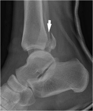
Figure 3-18. Trimalleolar fracture. The figure shows vertical fracture through the posterior malleolus (arrow) with posterior and superior displacement of the fracture fragment.
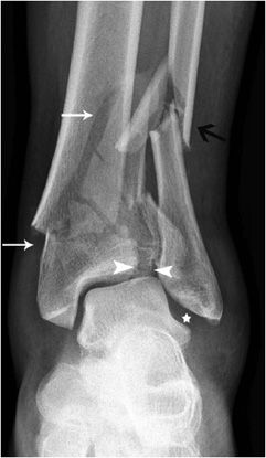
Pilon is French for “pestle,” a device used for crushing or grinding. In many “pilon fractures,” the bones of the ankle joint are crushed due to the high-energy impact causing the injury. The mechanism of injury is vertical loading, which drives the talus into distal tibia. Foot position and extent of energy affect the injury pattern. If the foot is held in plantar flexion, it results in posterior articular damage. Dorsiflexion causes anterior articular damage. Pilon fractures (Figure 3-19) need to be evaluated with CT, as the true extent of injury is best seen and assessed with this modality.13 Because of the energy required to cause this type of fracture, 25–50% of patients have additional injuries that require treatment.
Figure 3-19. Pilon fracture. The figure demonstrates comminution at the articular surface of the tibial plateau and fracture extension into the distal tibial shaft (arrows). The syndesmosis is disrupted (arrowheads) and there is widening of the lateral clear space (star). There is also a comminuted distal fibular fracture with medial angulation at the fracture apex (black arrow).
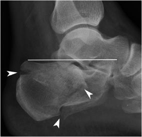
The calcaneus, the largest tarsal bone, is specifically designed to support the body and can endure a great degree of force. Calcaneal fractures (Figure 3-20) are divided into two major categories: intra-articular and extra-articular. Because of the axial load mechanism, calcaneal fractures can be associated with burst fractures of the spine, commonly at the thoracolumbar junction. Approximately 75% of calcaneal fractures are intra-articular and result from axial loading. Usually they have poor outcomes, since the articular surfaces, calcaneal fat pad, and peroneal tendons are injured, with resultant change in mechanical forces acting at the ankle joint.14 This leads to development of posttraumatic osteoarthritis.
Figure 3-20. Comminuted calcaneal fracture. Comminuted calcaneal fracture (arrowheads) with flattening of Böhler’s angle (line), which is normally 20–40.
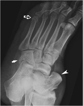
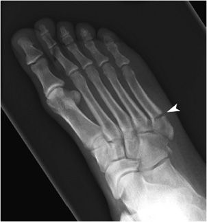
Subtalar dislocation (Figure 3-21) is the simultaneous dislocation of the talocalcaneal and talonavicular joints. Up to 85% of dislocations are medial.15 CT is performed after closed reduction to assess for congruency at the joints and associated fractures. Sometimes bone fragments or entrapped soft tissues can prevent adequate reduction. The cuboid bone fracture in this image is caused by a crushing force to the cuboid against the calcaneus and the fourth and fifth metatarsal bases, a so-called “Nutcracker fracture.” Also seen is a fracture of the fifth metatarsal neck, which usually heals without complication. That is contrary to the fracture at the proximal shaft of the fifth metatarsal bone (Figure 3-22), a so-called “Jones fracture.” For several reasons, a Jones fracture often does not heal. The diaphyseal bone, where the fracture occurs, is an area of poor blood supply (a watershed area). In addition, there are various tendons, including the peroneus brevis and fibularis tertius, and two small muscles attached to the bone. These may pull the fracture apart and prevent healing.
Figure 3-21. Subtalar dislocation. The figure demonstrates a bare talar head (arrowhead), not articulating with the navicular bone. There is a comminuted cuboid bone fracture (arrow) and a transverse fracture through the fifth metatarsal neck (open arrow).
Figure 3-22. Jones fracture. Fracture of the base of the fifth metatarsal bone (arrow).
FOOT
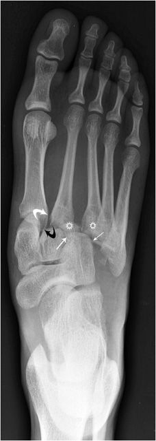
The Lisfranc fracture (Figure 3-23) is a fracture of the foot in which dislocation or subluxation occurs at the tarsometatarsal joint. This injury is caused by forced plantar flexion and twisting of the forefoot. Lisfranc injuries are subdivided into homolateral injuries, which means all five metatarsals are displaced in the same direction. Divergent injuries usually involve medial displacement of the first metatarsal and lateral displacement of the second through fifth metatarsals. The latter are usually more severe. Typically the base of the second metatarsal bone is fractured and there may be fractures of multiple metatarsal shafts, the cuboid, and cuneiform bones. For detailed evaluation, a CT scan is necessary. Lisfranc’s ligament diagonally connects the medial cuneiform bone to the base of the second metatarsal. It is one of the most important ligaments at the base of the foot. Lisfranc injuries can be difficult to diagnose and one should be wary of a foot injury with persistent pain. These patients should be reevaluated with weight-bearing views of the injured foot.
Figure 3-23. Lisfranc’s fracture dislocation. The first metatarsal base does not align with the medial cuneiform (curved white arrow); same is seen at the second tarsometatarsal joint (curved black arrow). The third metatarsal should align with the lateral cuneiform (stars). The fourth metatarsal base should align with the medial base of the cuboid bone (small white arrows).
Stay updated, free articles. Join our Telegram channel

Full access? Get Clinical Tree


