Comparison of verbal numeric pain scale
Baseline
2 weeks after injection
12 weeks after injection
Ultrasound-guided approach
6.15 ± 0.79
3.20 ± 0.51
2.62 ± 0.45
Fluoroscopy-guided approach
6.06 ± 0.82
3.17 ± 0.52
2.61 ± 0.42
Scanning Technique and Anatomy to Identify
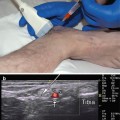
The patient should lay in a lateral decubitus position with the affected side towards the ceiling or supine with the head rotated away from the affected side. The transducer is placed transversely, short axis to the C7 level. At this level, identify the prominent posterior tubercle and rudimentary anterior tubercle [10]. The anterior and posterior tubercles of the cervical vertebrae, “the two-humped camel,” become more evident as you scan cranially to C6. The nerve root is identified as a hypoechoic round structure between the two tubercles [11]. Another method for identifying the correct cervical level is to trace the vertebral artery which lies anterior to C7 and enters the C6 foramen 90 % of time. The remaining 10 % enter further cranially [12]. Be careful to keep the transducer perpendicular to the relevant cervical level as you travel to another level so you do not have the transducer angled downward at an unintended level. Use Doppler to identify the larger carotid artery, anterior and superficial to the anterior tubercle. Look for an anteriorly located vertebral artery. Lastly, try to identify any smaller feeder vessels in the foramen or in the way of the projected needle pathway (Fig. 10.1).
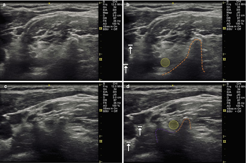
Fig. 10.1
(a) Transverse (axial) view over C7 with prominent posterior tubercle. (b) Dashed orange line outlines posterior tubercle, yellow indicates C7 spinal nerve, arrows with stops indicate carotid artery and internal jugular vein. (c) Transverse (axial) view over C6 with prominent anterior and posterior tubercles. (d) Dashed orange line outlines posterior tubercle, dashed purple line outlines anterior tubercle, yellow indicates C6 spinal nerve, arrows with stops indicate carotid artery and internal jugular vein
Injection Technique: In-Plane Axial Approach
Patient positioning: Lay the patient in the lateral decubitus position with the affected side facing upward with a pillow placed between the patient’s legs and one under the arm to facilitate comfort. The patient can also lay supine with the head rotated and side bent away.
Probe positioning: Place the transducer transverse (short axis) over the C7 vertebrae, visualizing the rudimentary anterior tubercle and prominent posterior tubercle (Fig. 10.2a).
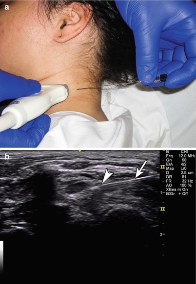
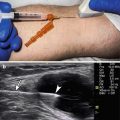
Fig. 10.2
(a) Example of transverse (axial) probe position over C6 level with in-plane needle position. (b) Example of in-plane axial injection towards to the C6 spinal nerve (probe angled slightly to position posterior tubercle out of the field of view to allow for easier needle trajectory), arrowhead indicates needle tip, arrow indicates needle
Markings: Identify the transverse process and tubercles of C7 as this differs from the other cervical vertebrae, marking the C7 level. If more than one level injection is planned, use a marker to identify the probe position at the desired vertebral levels and the needle entry site. Mark any vessels that are identified on Doppler to avoid inadvertent injury.
Needle position: Plan your needle path prior to insertion to avoid any feeding vessels or ones located in the posterior foramen. A blunt needle should be inserted from a posterior to anterior direction. The needle should be kept in-plane directed towards the desired nerve root.
Safety considerations: Care should be taken to avoid contact with a blood vessel or spinal nerve.
Pearls:
The anterior spinal artery may receive some blood flow from the ascending and deep cervical arteries [1].
Keep the transducer perpendicular as you scan to keep your desired vertebral level in site. Angling the transducer may cause you to view up or down a level.
Always inject from a posterior to anterior direction to avoid the internal jugular vein, vagus nerve, common carotid artery, and 80 % of anterior located radicular arteries in the cervical foramen.
Doppler mode may help to identify feeding vascular structures in the posterior foramen.
Equipment needed:
6–12 MHz linear array transducer
22 or 25 gauge, blunt tip spinal needle
Non-particulate steroid preparation
1–2 mL of local anesthetic or normal saline
Cervical Medial Branch Blocks (CMBB) and Third Occipital Nerve (TON)
Pain arising from the cervical zygapophysial (z-jt) aka facet joint is common and may present with aching or throbbing neck pain that radiates to the head (commonly C2–3) or shoulder or interscapular region (C5–6, C6–7) [13]. Patients may have pain and decreased range of motion with cervical side bending or rotation. The cervical z-jts are each innervated by two medial branches, and pain emanating from the joint is diagnosed by anesthetizing these nerves. Injection of the joints themselves is not as helpful diagnostically but may provide therapeutic benefit [14, 15]. Cervical medial branch block procedures are typically performed with fluoroscopic guidance but have the potential to miss the medial branch as there are variations in its course [16]. Ultrasound provides the opportunity to visualize the nerve towards the center of the articular pillars. The gold standard treatment for cervical z-jt pain is radiofrequency neurotomy, and the use of ultrasound guidance to perform the procedure has been described and may become a viable alternative to fluoroscopy [17, 18] (Table 10.2).
Level | Accuracy (%) |
|---|---|
Third occipital nerve | 88 |
C4 | 94 |
C6 | 88 |
C7 | 41 |
Scanning Technique and Anatomy to Identify
The patient should lie in the lateral decubitus position. The transducer is placed longitudinally with the superior end on the mastoid process to obtain a coronal image. The articular pillars of the cervical vertebra (C2–7) are seen as hills, and the first trough between the hills of the C2–3 z-jt is identified by a characteristic depression. To confirm your level, the transverse process of C1 can be seen on the cephalad portion of the screen or turn on the Doppler to visualize the vertebral artery traversing anteriorly into the foramen of C2 [11]. The superficial medial branch of C3 differs from the other cervical medial branches in that it sits on top of the “hill” at the junction of the C2–3 z-jt and travels to become a cutaneous nerve. This is known as the third occipital nerve (TON). The TON can also be identified by placing the transducer over the mastoid process in the axial plane and moving it caudally until the transverse process of C1. Continuing caudally, the vertebral artery traverses into the foramen of C2 [20]. The TON is identified at the highest point of the convexity of the C2–3 joint [21]. The C4–8 cervical medial branches traverse dorsally over the articular pillars in the troughs between the hills and innervate the facet joint above and below [22]. They are found by the continuation of the longitudinal (coronal) scanning along the articular pillars. The medial branches appear as oval slightly hypoechoic structures in between the pillars (Fig. 10.3).
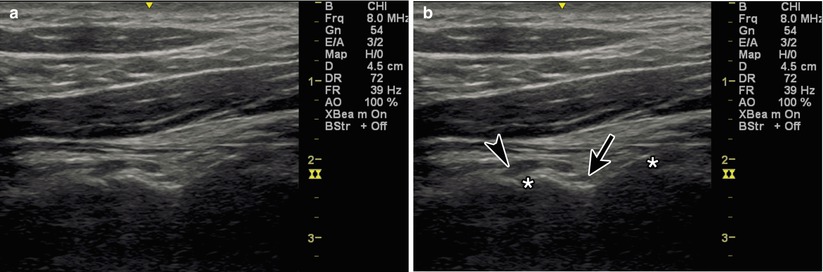
Fig. 10.3
(a) Coronal view of the cervical articular pillars. (b) Black arrowhead indicates TON, black arrow indicates C3 medial branch, asterisk indicates C2–3 and C3–4 z-jt
Injection Techniques: In-Plane Coronal Approach
Patient positioning: Lay the patient in the lateral decubitus position with pillows underneath the head, between the legs, and under the arm.
Probe positioning: Place the transducer coronally over the mastoid process and view the articular pillar, identifying the levels as you move caudally (Fig. 10.4a).
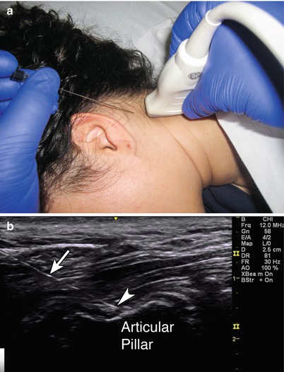
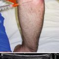
Fig. 10.4
(a) Example of coronal view over the cervical medial branches with in-plane needle position. (b) Arrowhead indicates needle tip adjacent to medial branch, white arrow indicates needle, articular pillar labeled
Markings: Identify and mark the desired cervical levels.
Needle position: The needle is inserted in-plane towards the medial branch if identified. If the nerve is not visualized, direct straight down between the articular pillars towards the deepest point, touching down on bone. For the TON, the needle is inserted in-plane towards the apex of the C2–3 joint.
Safety considerations: Keep the transducer and injection posterior to avoid the anterior vasculature.
Pearls for CMBB:
Aim at the deepest point between the articular pillars.
The medial branch may be difficult to visualize in an obese patient.
The cervical medial branch becomes more difficult to identify as you proceed caudally.
Pearls for TON:
Aim at the convexity of the C2–3 joint.
The C2 level is also identified as having the first bifid spinous process [23]. The transducer can be placed axially over the spinous process of C2, and the lamina of C2 can be traced laterally until the C2–3 joint appears.
Equipment needed:
High-frequency linear array transducer
22 or 25G 2.5–3.5″ spinal needle
0–1 mL of steroid preparation per level
0.5–1 mL local anesthetic per level
Cervical Zygapophysial Joint
The cervical z-jts are formed by the articulations of the superior and inferior articular pillars of adjacent vertebrae. Intra-articular injections can have diagnostic and therapeutic benefit [15, 24]. Cervical z-jt joint procedures are typically performed with either fluoroscopic or CT guidance. Ultrasound-guided cervical facet joint injections have been shown to be faster than CT guidance, require fewer needle repositions, and have better pain scores at 1 month [25].
Scanning Technique and Anatomy to Identify
The patient should lie in the prone position. The transducer is placed midline in the sagittal plane (longitudinally) over the cervical spinous processes. The C2 level is identified as having the first bifid spinous process [13]. The cervical levels are counted as you move caudally by looking at the superficial midline hyperechoic spinous processes. Once you reach your desired level, moving the transducer laterally will bring a sawtooth image of the z-jt line into view. The z-jts become more vertical as you move caudally, becoming almost vertical in the thoracic spine [26, 27] (Fig. 10.5).
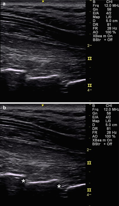
Fig. 10.5
(a) Sagittal view of the cervical facet joints. (b) Asterisk indicates cervical facet joints
Injection Technique: In-Plane Sagittal Approach
Patient positioning: Lay the patient in the prone position with a pillow underneath the chest to allow for slight cervical flexion.
Probe positioning: Place the transducer in the sagittal plane over the cervical spinous processes and move laterally until the facet joints at the desired levels are in view (Fig. 10.6a).
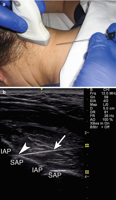
Fig. 10.6
(a) Example of sagittal probe position over cervical facet joint with in-plane injection technique. (b) Arrowhead indicates needle tip entering facet joint, arrow indicates needle, IAP inferior articular process, SAP superior articular process
Marking: Identify and mark the desire cervical levels.
Needle position: The needle is inserted in-plane from caudal to cephalad towards the facet joint.
Safety considerations: Keep the transducer and injection posterior to avoid the anterior vasculature.
Pearls:
The cervical facets appear as shingles on a roof with the probe in the sagittal plane.
Keeping the needle angle shallow will help to mimic the angle of the facet joint and ease the approach and needle placement for an intra-articular injection.
The C2 vertebra has the first bifid spinous process.
Equipment needed:
High-frequency linear transducer
25 gauge, 1.5″ needle
0.5–1 mL of steroid preparation per level
0.5–1 mL of local anesthetic per level
Stellate Ganglion
Stellate ganglion block (SGB) is an established treatment for sympathetically mediated pain conditions such as complex regional pain syndrome and Raynaud’s disease [28]. The most widely practiced approach for this injection was originally described by Leriche [29], in which Chassaignac’s tubercle, the anterior aspect of the C6 transverse process, is palpated and used as the needle target [30]. This approach is typically performed with or without fluoroscopy [31]. However, the stellate ganglion does not lie adjacent to this bony target but rather anteriorly in the prevertebral fascia [32, 33].
The stellate ganglion, or cervicothoracic ganglion, is the fusion of the inferior cervical ganglion and the first thoracic ganglion. The stellate ganglion lies posterior and lateral to the trachea, esophagus, and thyroid; medial to the common carotid artery and internal jugular vein; just lateral to the inferior thyroid artery and recurrent laryngeal nerve; and anterior to the vertebral artery and longus colli muscle [34]. The stellate ganglion is approximately 2.5 cm long, 1 cm wide, and 0.5 cm thick [35]. The fluoroscopic-guided approach cannot visualize any of these soft tissue structures. Ultrasound improves safety by allowing direct visualization of the related anatomical structures minimizing complications like recurrent laryngeal nerve palsy or inadvertent puncture of a major vessel with intravascular spread [36]. Ultrasound also helps to avoid retropharyngeal hematoma, which is reported to occur in 1/100,000 procedures; however, asymptomatic hematoma can be as high as 1/4 [37].
Scanning Technique and Anatomy to Identify
Place the patient in the supine position with the head in slight extension and rotated away from your desired side. Place the probe over the cricoid cartilage to obtain a transverse (axial) scan, and move laterally to identify the prominent anterior tubercle of C6. In this position, identify the carotid artery, internal jugular vein, cricoid cartilage, and longus colli muscle. Turn on the Doppler to look for the inferior thyroid artery and a vertebral artery that may not have moved posteriorly into the vertebral foramen yet [36]. To confirm your anatomical level, scan in the axial plane laterally over C7. C7 has a prominent posterior tubercle and a rudimentary anterior tubercle which differentiates it from C6 which has both anterior and posterior tubercles (Fig. 10.7).
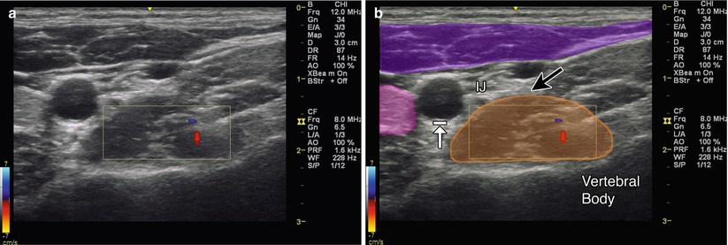
Fig. 10.7
(a) Transverse (axial) view of the stellate ganglion with Doppler. (b) Magenta indicates sternocleidomastoid, purple indicates anterior scalene, orange indicates longus colli, black arrow indicates location of stellate ganglion, arrow with stop indicates carotid artery, IJ internal jugular vein
Injection Technique: In-Plane Axial Approach
Patient positioning: Lay the patient supine with the neck in slight extension and slight rotation away.
Probe positioning: Start by placing the probe at C7 in the axial plane. As you scan cephalad, the anterior tubercle of C6 comes into view. Now at the level of C6, visualize the anterior tubercle of C6, longus colli muscle and prevertebral fascia, carotid artery, and thyroid gland (Fig. 10.8a).
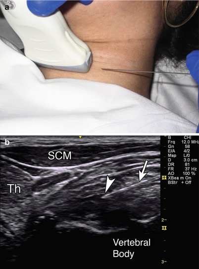
Fig. 10.8
(a) Example of axial probe position over stellate ganglion at level of C6 with in-plane injection technique. (b) Arrowhead indicates needle tip in the prevertebral fascia, white arrow indicates needle, SCM sternocleidomastoid, Th thyroid, vertebral body labeled
Markings: There are a number of significant anatomical structures to mark and note in this region. Identify the esophagus, trachea, carotid artery, internal jugular vein, and inferior thyroidal artery.
Needle position: The needle is inserted in-plane from lateral to medial aiming at the prevertebral fascia just anterior to the longus colli muscle. Plan out the course of the needle to avoid puncturing important structures [8]. If the needle path can cause injury to these structures, adjust the probe position or insert the needle with a more oblique trajectory.
Safety considerations: Avoid the esophagus and trachea medially and the carotid artery, internal jugular vein, inferior thyroid, and vertebral arteries laterally. A phrenic nerve block can occur and cause diaphragmatic paresis [38].
Pearls:
The stellate ganglion lies medial to the scalene muscles.
Stellate ganglion is formed by the fusion of the inferior cervical and first thoracic ganglion.
A nerve stimulator can help to identify the phrenic nerve and avoid inadvertent diaphragmatic paresis [39].
Equipment needed:
High-frequency linear array transducer
25G 3.5″ needle
1–3 mL short-acting anesthetic for local anesthesia
10–20 mL of long-acting anesthetic for the block
Greater Occipital Nerve
Greater occipital nerve (GON) block is used to treat occipital neuralgia and different headache conditions such as cluster, tension, cervicogenic, and migraine [39–42]. Occipital neuralgia is typically described as a painful paroxysmal stabbing pain in the distribution of the greater, lesser, and third occipital nerves [43]. Patients may exhibit tenderness over the affected nerve. The classical method of blind injection includes palpating just medial to the occipital artery at the level of the superior nuchal line [44]. Identification of the occipital artery by palpation can be difficult, however, and there can be variability in the course of both the occipital artery and GON. The GON arises from the C2 dorsal ramus and curves around the inferior aspect of the inferior oblique muscle (IOM) to then situate between the IOM and the semispinalis capitis (SSC) muscle [45]. There are a number of locations in which the GON can become irritated and entrapped including where the greater occipital nerve emerges from the C2 dorsal ramus between the atlas and the axis, where the nerve courses between the IOM and SSC muscles, and where the nerve pierces the belly of the SSC and at the nerve exit from the tendinous aponeurosis of the trapezius [46, 47] (Table 10.3).
Table 10.3
Accuracy of ultrasound guided GON injections
Study – GON | Author | Accuracy (%) |
|---|---|---|
Ultrasound guided | Siegenthaler et al. [21] | 100 |
Scanning Technique and Anatomy to Identify
The patient should lay prone on a table or cervical board with slight cervical flexion to expose the suboccipital region. Place the ultrasound probe transversely over the hyperechoic bony bifid C2 spinous process, and scan one level cephalad to C1. Identify the IOM just superficial to C1 and the SSC muscle superficial to that. The GON appears as a hypoechoic round or oval structure that lies within the plane of these two muscles before it pierces superficially through the SSC [48]. Use Doppler to visualize any branches of the occipital artery (Fig. 10.9).
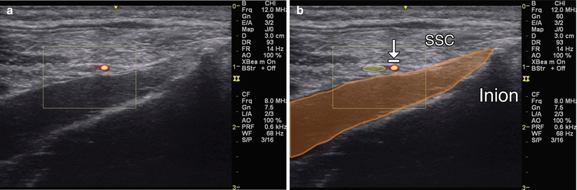
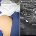
Fig. 10.9
(a) Axial view of the GON with Doppler. (b) Orange indicates IOM, SSC and inion labeled; arrow with stop indicates occipital artery; yellow indicates GON
Injection Technique: In-Plane Axial Approach [49]
Patient positioning: Lay the patient prone with the neck in slight flexion. A pillow can be placed under the chest.
Probe positioning: Start by placing the transducer transverse (axial) over the bifid spinous process of C2. The posterior arch of C1 will appear smooth. The inferior obliquus capitis muscle attaches to the spinous process of C2 and transverse process of C1. Follow the inferior obliquus capitis in-plane as it moves laterally and cranially. The GON sits in the fascial plane between the inferior obliquus capitis and semispinalis capitis muscle (Fig. 10.10a).
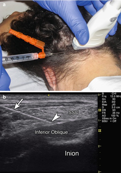
Fig. 10.10


(a) Example of axial probe position over GON with in-plane injection technique. (b) Arrowhead indicates needle tip adjacent to GON; white arrow indicates needle; SSC, inion, and inferior oblique labeled
Related posts:
Stay updated, free articles. Join our Telegram channel
Full access? Get Clinical Tree
