(1)
Cleveland Clinic, Emeritus Staff, Cleveland, OH, USA
Keywords
Data storageDisplayDICOMPACSEHRTeleradiologyIntroduction
Completion of a nuclear medicine procedure involves many steps that are intertwined with one another. A referring physician orders a nuclear medicine study for a patient after clinical examination. The patient reports to the nuclear medicine department for the study according to the schedule. The study is performed according to the established protocol using specific equipment. The data are processed and used to construct images which are then stored for display on monitors as needed. The nuclear physician retrieves the images from storage and interprets them to diagnose the patient’s diseases. The report on the diagnosis is dictated into a computer, which can be retrieved along with images by the referring physician for making a clinical decision for the patient. The entire sequence of operations in the procedure is depicted by the term workflow that represents each operation much like flowcharts. Workflow software has been developed by various vendors to implement all sequential operations of a procedure in an integrated form. The advantage of workflow lies in the management of large imaging data in multiple formats along with the capability of interrelating among different operations. Below is given a description of storage and display of image data in nuclear medicine and the concept of workflow involving multiple operations to complete a study.
Storage
Reconstructed digital PET images are stored in the computer in the format of a matrix. The images are characterized by two quantities: matrix size and pixel depth. In PET studies, the computer memory approximates the FOV as a square matrix of a definite size that can range from 64 × 64 to 512 × 512 with a total of 1026 (1 K) to 262,144 (262 K) picture elements, called pixels, respectively. The matrix size depends on the type of study and is chosen by the operator. Since the FOV is approximated to the matrix size, the pixel size is calculated by dividing the length of FOV by the number of pixels across the matrix. For example, if an image of 250 × 250 mm FOV is stored in a 128 × 128 matrix, then the pixel size would be 250/128 ≈ 2 mm. The spatial resolution of an image is improved by decreasing the pixel size but is limited by the spatial resolution of the scanner. Pixel size smaller than one-third the spatial resolution of the PET system does not improve the image resolution any more. Thus, for a 6-mm spatial resolution, choosing pixel size smaller than 2 mm does not add to the improvement of the image resolution.
How many counts can be stored in a pixel depends on the depth of the pixel, which is represented by a byte or a word. Digital computers operate with binary numbers using only 2 digits, 0 and 1, as opposed to 10 digits, 0–9, in the decimal system. The basic unit of the binary system is a bit (binary digit) that is either 0 or 1. In computer nomenclature, a byte of memory is equal to 8 bits that can store up to 28, i.e., 0–255 units of information. Similarly, a word of memory consists of 16 bits or 2 bytes and can store up to 216, i.e., 0–65,535 units of information. The color levels or gray shades on the displayed images are affected by pixel depth. Currently 32-bit and 64-bit processors have been introduced, allowing storage capacity of 232 and 264 units of information in computers.
After completion of a PET study, the images are archived in long-term storages, which are available in a variety of hardware accessories. In the past the scope of PET imaging was limited and the digital images could be stored in the hard drive of the local computers with capacity of several gigabytes. As the technology expanded and PET imaging grew tremendously, demand for larger storage became enormous. External storage like optical disk, magnetic tape, spinning media, etc., was utilized for storage with more capacity. For reasons of natural disasters, terrorism, viruses, etc., electronic data vaulting was accepted as a plausible merging technique for off-site data storage, which provides a means for geographically distant storage and retrieval of data as needed. The distant storage, however, requires strict security of the storage facility to ward off any natural calamity and criminal attack.
Nowadays the prolific growth of PET modality has prompted the need for storage capacity of tens to hundreds of terabytes (TB). Vendors have developed a unique system called picture archiving and communication system (PACS) (described later) for storage of massive volume of PET images. PACS utilizes magnetic hard drives with capacity of several hundred terabytes and they are managed by secure and reliable software. The PACS software includes provision for disaster recovery, backup, and replication. Various features of PACS are discussed in detail later.
Recently, internet-based cloud-computing has drawn enormous attention in medical imaging because of its vast storage capacity and ease of exchange of stored information among institutions and individuals on-site and remotely in real time (Kagadis et al. 2013). Faster network communication and decreasing cost has made cloud computing very attractive in archiving medical information. Vendors now are introducing cloud-based PACS taking advantage of versatile features of cost-effective storage capacity and easy data interchange over the internet. It can be accessed from any location, provided an internet connection is available. Clinical information and diagnostic images stored in cloud can be shared among physicians and medical institutions, which improves the patient care. However, strict cyber security and data encryption are challenges in cloud computing and must be implemented meticulously.
Display
Images are displayed on video monitors after the conversion of digital images into analog images by digital-to-analog conversion (DAC) at the video interface between the computer and the monitor. Two common video monitors are cathode ray tubes (CRTs) or flat panel-type liquid crystal display (LCD) monitors. These monitors are characterized by parameters such as spatial resolution, contrast resolution, aspect ratio, luminance, persistence, refresh rate, and dynamic range. These properties are described in standard physics books on imaging and are not discussed here. It should be noted that the spatial resolution and luminance of LCD monitors are far superior to those of CRTs. These monitors are set in what is called the workstation, where practitioners manipulate, view, and interpret images using the computer attached to the workstation.
Display can be in either grayscale (black and white) or color-scale format. Grading of scale in either case is dictated by the pixel values (number of counts in the pixel) in the digital image. The number of counts in a pixel defines the brightness level of the pixel. Thus, in a digital image, the grayscale can be applied to delineate areas of contrast, and when comparing separate images, the grayscale should be kept the same for all images.
Color display of digital images can be obtained by assigning color hues to different pixel values corresponding to counts stored in the individual pixels. In a common color scale, blue, green, yellow, and red colors from the visible spectrum are in order assigned to pixels with increasing counts: blue color to the pixels with the lowest counts and red color to the pixels with the highest counts. Edges of color bands are blended to produce a gradual change over the full range of the color scale. As with the grayscale, the color scale provides contrasts between areas of different pixel counts and thus a means to discriminate between normal and abnormal areas on the images. Conventionally, PET functional images are displayed in color, and CT anatomical images are shown in grayscale. On fusion of the two images, the combination of color and grayscales is quite effective in differentiating the abnormal areas.
Often a grayscale or color-scale bar is shown on the side of the image so that the interpreter can easily differentiate the contrast on the image. The regions of interest (ROIs) can be chosen from sequential images, and time–activity curves can be obtained by plotting counts in ROIs against the corresponding time. Images can be subtracted from one another or can be superimposed, as needed.
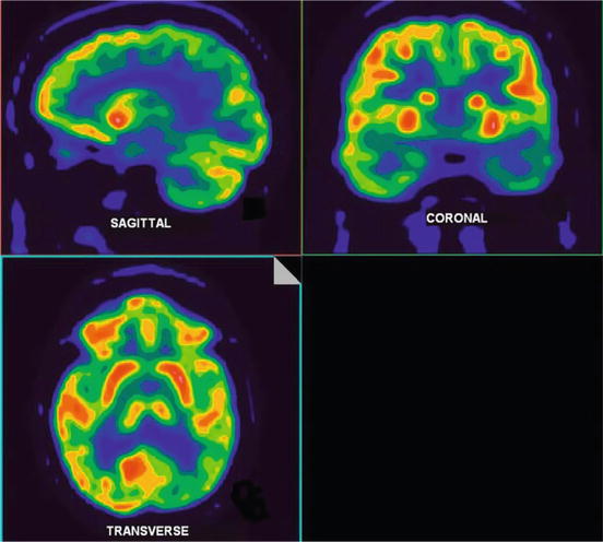
PET images can be displayed in transaxial, coronal (horizontal long axis), or sagittal (vertical long axis) views separately or simultaneously on the same screen (Fig. 5.1). On a simultaneous display, a point within an image of the object is chosen using the cursor and three images that pass through that point are displayed. New sets of images are obtained by moving the cursor to a different point along the image. Such sequential screening of images is helpful in delineating the abnormal areas in patients on images.


Fig. 5.1
Simultaneous display of PET images of the brain in transaxial, coronal (horizontal long axis), and sagittal (vertical long axis) orientation
Angular projections around an object can be computed from the three-dimensional (3D) tomographic data and then displayed in continuous rotation. This results in the presentation of the image data in a movie or cinematographic (or cine) mode whereby a rotating 3D image is seen on the screen. The relative location of a lesion in an organ with respect to other organs in the body can be easily identified in these movie presentations of PET images.
Software and DICOM
Commercial vendors provide software for acquisition, processing, storage, and display of images specially designed for their scanners. Such software is either developed by the vendor or acquired from a third-party software developer. These types of software use a proprietary format for each vendor, and it is difficult to transfer, store, and display images on equipment from different vendors.
This problem can be partially solved by using equipment all from the same vendor in an institution. To overcome this difficulty, the American College of Radiology (ACR) and the National Electrical Manufacturers Association (NEMA) jointly sponsor a standard format for software called Digital Imaging and Communications in Medicine (DICOM) to facilitate the transmission and usage of medical images and related data among different imaging equipment. DICOM consists of a standard image format as well as a network communication protocol and specifies standard formats for operations such as Patients, Studies, Storage, Query/Retrieve, Verification, Print, Study, etc.
Currently, all vendors provide software conforming to the DICOM standard and agree to a commitment to that effect to all customers. Compliance with this standard establishes a common format for imaging systems connecting hardware and software components and allows interoperability for transfer of images and associated information among multiple vendors’ devices. The DICOM standard is particularly useful in the implementation of PACS, which is discussed below.
Picture Archiving and Communication Systems
The PACS is a system for storage of images and transferring images between computers in different facilities through networks. This system consists of devices to produce and store digital images electronically, workstations to view and interpret images, and a network linking computers from different sites. Appropriate PACS software allows the interpreter to manipulate images as needed, at his own location, by retrieving images from other locations via PACS. The introduction of PACS has eliminated the use of X-ray films or Polaroid films for routine interpretation of images, making the imaging centers filmless.
Stay updated, free articles. Join our Telegram channel

Full access? Get Clinical Tree


