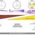
Fig. 36.1
Assessment of prosthesis positioning relative to the left coronary ostium and aortic annulus by MDCT. MDCT enables the visualization of the position of the prosthetic valve in relation to the aortic annulus and left coronary ostium: below the coronary ostium (a), at the same level of the coronary ostium (b), or overpassing the height of the coronary ostium (Reproduced with permission from [8]) (c)
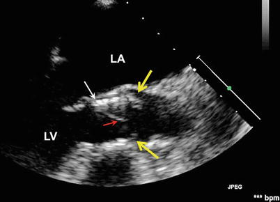
Fig. 36.2
Low-positioned THV with native leaflet “overhang”. The TEE long-axis view shows a low position of the THV (white arrow) with the uncovered cusps of the native valve (yellow arrows) overhanging above the distal rim of the THV stent. Red arrow indicates the THV cusp. LA left atrium, LV left ventricle
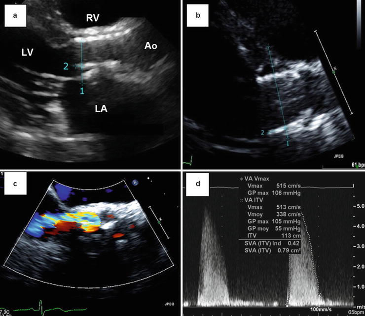
Fig. 36.3
Late migration of a balloon-expandable THV. These Doppler echocardiographic images show the case of a late (4 months post-TAVR) migration of a balloon-expandable SAPIEN THV toward the LV outflow tract. Panels (a) and (b) show the displacement of the valve predischarge to 4-month follow-up. The distance between the apical end of the stent (1) and the hinge point of the anterior mitral leaflet (2) increased from 3.2 to 9.6 mm between the two echocardiograms. Other images obtained at 4-month post-TAVR reveal a moderate paravalvular regurgitation (Panel c) and a high mean transprosthetic gradient (55 mmHg, Panel d). Ao aorta, LA left atrium, LV left ventricle, RV right ventricle
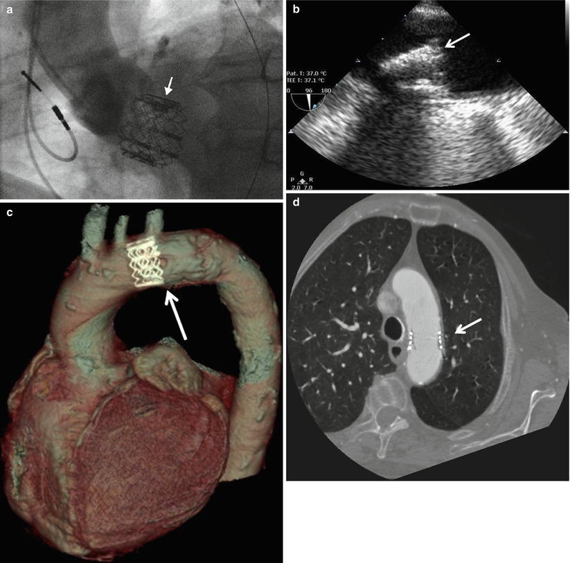
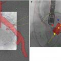
Fig. 36.4
Embolization of THVs assessed by multimodality imaging. Panel (a): Cinefluoroscopic image of a THV migration in the LV outflow tract (Reproduced with permission from [14]); Panel (b): TTE image of a THV embolization in the proximal descending aorta visualized; Panels (c) and (d): MDCT images of THV embolization in the aortic arch (Courtesy of Dr Jonathon Leipsic, St Paul Hospital, Vancouver). The white arrows indicate the THV
THV Expansion
The adequacy of THV expansion can be assessed by calculating the ratio of the MDCT-derived external area of the valve stent to the nominal external area of the THV, expressed in percent (Fig. 36.5) [8, 10]. An underexpanded valve is defined as having an expansion ratio of ≤90 %. In a recent study, Willson et al. found that 8 % of patients have underexpanded valves following TAVR with balloon-expandable THV. Underexpansion occurred predominantly at the inflow level. Valve underexpansion may be associated with prosthetic valve stenosis or regurgitation [10].
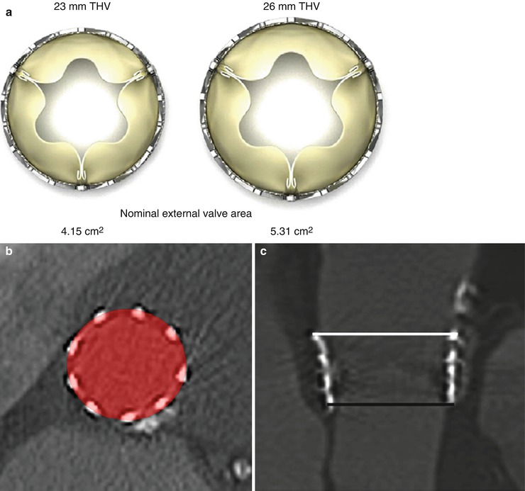
Fig. 36.5
THV expansion as assessed by MDCT. (a) Nominal external valve area of the 23- and 26-mm balloon-expandable SAPIEN valves. (b) THV expansion is calculated by dividing MDCT-derived external valve area by nominal external valve area. (c) A SAPIEN 26-mm valve underexpanded at the inflow with increasing expansion toward the outflow level (inflow external valve area = 460 mm2, inflow expansion = 86.5 %, outflow external valve area = 597 mm2, outflow expansion: 112.4 %) (Reproduced with permission from [10])
THV Eccentricity or Circularity
The minimum external diameter, maximum external diameter, and external valve area are measured by MDCT at three cross-sectional levels: inflow, mid-stent, and outflow. THV eccentricity is calculated as 100 × (1–minimum external stent diameter/maximum external stent diameter). Noncircular deployment of THV is generally defined as an eccentricity >10 %. In balloon-expandable THVs, earlier studies reported that about 15 % of patients have noncircular deployment [8], whereas more recent studies reported <5 % of THV noncircularity [10]. The patients with noncircular deployment of the stent more often have larger aortic annulus and more calcified native valves (Fig. 36.6) [8]. The presence of large bulky calcifications at the level of the native valve cusps, aortic annulus, or LV outflow tract (LVOT) may predispose to a less circular deployment of the stent and thus to prosthetic valve regurgitation or stenosis (Figs. 36.6 and 36.7). Noncircular deployment of the stent might also reduce the durability of the valve due to increased mechanical stress upon the valve cusps.
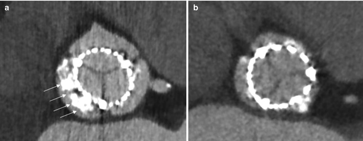
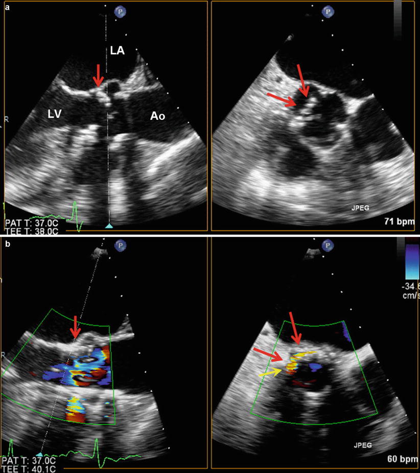
Fig. 36.6
THV deployment as assessed by MDCT. MDCT is helpful to evaluate THV prosthesis deployment. Panel (a) should a noncircular deployment of the valve associated with heavily, bulky calcified native aortic cusps. Panel (b) shows circular deployment of the valve (Reproduced with permission from [4])
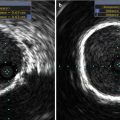
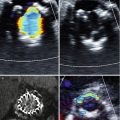
Fig. 36.7
Relation between native valve calcification and THV paravalvular regurgitation. Panels (a) and (b) show TEE long- and short-axis views of large bulky calcification of native aortic valve cusp (red arrows) prior to TAVR (a) and ensuing paravalvular regurgitation (yellow arrow) after TAVR (b). Ao aorta, LA left atrium, LV left ventricle
Structural Integrity of the THV Stent and Surrounding Structures
Structural integrity of the THV stent can be assessed by MDCT or cinefluoroscopy. Until now, there has been no report of stent fracture with the currently used THVs [3, 4, 10]. The structural evaluation should also include the assessment of the impact of the TAVR procedure and of the THV on the surrounding anatomical structures, i.e., the mitral valve, the aortic root, and the left ventricular wall. In particular, if the landing zone of the stent is low in the LVOT, the apical end of the stent may cause an erosion and perforation of the anterior mitral leaflet or of the membranous septum (Fig. 36.8). Owing to their high performance for anatomical imaging, MDCT or CMR is useful to assess the prosthesis and its relationship to the native aortic valve, annulus, root, mitral valve, and ventricle as well as detecting pseudo-aneurysms of the root or other rare complications (Fig. 36.9).
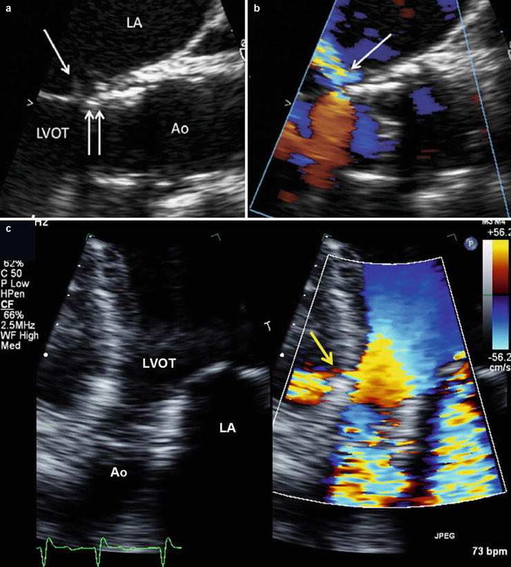
Fig. 36.8
Lesions of septum and mitral valve caused by THV. Panels (a) and (b) show TEE views of a delayed mitral valve injury (Reproduced with permission from [15]). Panel (a): The stent (double arrow) is in contact with the anterior mitral leaflet. Prosthetic valve endocarditis 1 year after implantation associated with perforation of the mitral leaflet at the point of contact (single arrow). Panel (b) Ensuing severe mitral regurgitation. Panel (c) shows a perforation of the membranous septum caused by THV stent and ensuing left-to-right shunt (yellow arrow). Ao aorta, LV left ventricle, LVOT LV outflow tract, RV right ventricle
Fig. 36.9
Pseudo-aneurysm of the aortic root visualized by MDCT. Coronal multiplanar reconstruction of the aortic root in an 89-year-old female patient 3 days after transcatheter aortic valve replacement. Difficulties with the rapid ventricular pacing were encountered, resulting in a low deployment, root injury, and a resultant pseudo-aneurysm (arrow) (Reproduced with permission from [3])
Assessment of THV Cusps Morphology and Mobility
Meticulous assessment of thickness, calcification, and mobility of valve cusps is key to detect the presence of tissue degeneration of surgical or transcatheter bioprosthetic valves, with echocardiography the method of choice for this purpose. THVs cause less reverberation and acoustic shadowing compared to surgical prostheses. The morphology and mobility of THV cusps can generally be adequately assessed by TTE. In cases where visualization of valve cusps is not feasible or inadequate, transesophageal echocardiography (TEE) can provide improved image quality and thereby improved detection of cusp calcification and thickening, vegetations due to endocarditis, thrombus or pannus, and reduced cusp mobility. MDCT may be useful to identify pannus or thrombus and to detect the presence of cusp calcification. Given that few patients have follow-up duration longer than 5 years after TAVR, there is very limited data about the structural and functional durability of THVs. However, there has been some reports of calcific degeneration of valve cusps [16].
Functional Evaluation
The evaluation of THV function includes the identification and quantification of prosthesis-patient mismatch (PPM) and acquired dysfunction, that is, stenosis and/or regurgitation. The functional evaluation of THVs is generally much more complex than that of native or surgical bioprosthetic valves because of the pitfalls in the measurement of the valve effective orifice area (EOA) and the high prevalence of paravalvular regurgitation.
Identification and Quantification of Prosthesis-Patient Mismatch
Prosthesis-patient mismatch is not an intrinsic dysfunction of the prosthesis, per se. This problem indeed occurs when the EOA of a normally functioning prosthesis is too small in relation to the patient’s body size (and thus cardiac output requirements), resulting in abnormally high postoperative velocities and gradients (Box 36.1) [17]. PPM is defined with the use of the EOA projected from normal reference values or measured early after valve replacement and then indexed for patient’s body surface area. Moderate PPM (indexed EOA < 0.85 cm2/m2) may be quite frequent (20–70 %) following surgical aortic valve replacement (SAVR), whereas the prevalence of severe PPM (indexed EOA < 0.65 cm2/m2) ranges from 2 to 20 % [17]. In SAVR series, PPM, and especially severe PPM, is associated with increased risk of operative mortality, less improvement in symptoms, less regression of LV hypertrophy, more adverse cardiac events, and reduced long-term survival [17]. This detrimental impact of PPM on outcomes is more pronounced in patients with depressed LV systolic function, severe LV hypertrophy, and/or concomitant mitral regurgitation.
Given that there are not yet normal reference values of EOA established for THVs and that these values may vary not only with the model and label size of THV but also with the patient’s aortic annulus size [18], the projected indexed EOA of THVs is presently difficult to obtain, and it is thus preferable to use the indexed EOA measured by echocardiography at predischarge or 1-month post-TAVR to detect the presence of PPM. However, the utilization of the indexed EOA measured early after TAVR may yield to overestimation of the degree of PPM in presence of low-flow states (i.e., indexed EOA may be “pseudo-severized”) or in presence of obesity (i.e., body surface area may overestimate cardiac output requirements). The incidence of moderate PPM reported in series of patients who received balloon- or self-expandable THVs is between 18 and 32 % and that of severe PPM was between 2 and 9 % [19–24]. Furthermore, PPM was associated with less regression of LV mass, volumes, and diastolic dysfunction as well as less functional improvement following TAVR [24]. It is also important to emphasize that the patient’s aortic annulus size in these TAVR series was, on average, much smaller compared to contemporary SAVR series. Accordingly, in a previous study where TAVR and SAVR cohorts were matched for aortic annulus size [19], the incidence of severe PPM was lower with TAVR (6 %) compared to SAVR (28 % with stented bioprostheses and 20 % with stentless bioprostheses). The superiority of TAVR over SAVR for the prevention of PPM was particularly obvious in the subset of patients with a small aortic annulus [19, 23]. However, these encouraging results will have to be further confirmed by randomized clinical trials. In PARTNER-Cohort A trial, TAVR was associated with significantly larger EOAs and lower gradients compared to SAVR [25, 26]
Box 36.1 Definitions of Moderate and Severe Patient-Prosthesis Mismatch
Severity | Effective orifice area (cm2/m2) |
|---|---|
None/Mild | <0.85–0.9 |
Moderate | <0.85 |
Severe | <0.65 |
Detection and Quantification of Prosthetic Valve Stenosis
Table 36.1 presents the proposed Doppler echocardiographic parameters and criteria for the detection and quantification of prosthetic valve stenosis following TAVR. As in patients with surgical bioprosthetic valves, acquired prosthetic valve stenosis is expected to be associated with abnormalities of cusps morphology and mobility (calcification and thickening of the valve cusps with reduced mobility). Quantitative parameters of prosthetic valve function include transprosthetic flow velocity and pressure gradients, valve EOA, and Doppler velocity index (DVI).
Table 36.1
Doppler echocardiographic criteria for detection and quantification of transcatheter heart valve stenosis
Normal | Possible stenosis | Significant stenosis | |
|---|---|---|---|
Structural parameters | |||
Valve stent and cusps | Usually normal | Normal/abnormala | Usually abnormala |
Doppler quantitative parameters | |||
Peak aortic jet velocity (m/s)b,c | <3 | 3–4 | >4 |
Mean gradient (mmHg)b,c | <20 | 20–35 | >35 |
Doppler velocity indexb,d | ≥0.35 | 0.25–0.35 | <0.25 |
Effective orifice area (cm2)b | >1.2 | 0.8–1.2 | <0.8 |
Contour of the transprosthetic jete | Triangular, early peaking | Triangular to intermediate | Rounded, symmetrical |
Acceleration time (ms)e | <80 | 80–100 | >100 |
Acceleration time/LV ejection time ratioe | – | 0.30–0.37 | >0.37 |
Transprosthetic Flow Velocity and Gradient
The principles of interrogation and recording of flow velocity through THVs are similar to those used in evaluating native valve stenosis [1, 3, 5, 11]. However, as in surgical prosthetic valves, high velocity or gradient alone is not proof of intrinsic prosthetic obstruction and may be secondary to PPM, high-flow conditions, prosthetic valve regurgitation, and technical pitfalls. Significant prosthetic valve regurgitation may indeed cause the flow rate across the prosthesis to increase, resulting in increased gradients. This phenomenon may be more frequent in transcatheter than in surgical valves, due to the higher incidence of paravalvular regurgitation in the former. It is also important to keep in mind that several conditions, e.g., PPM and intrinsic dysfunction (stenosis and/or regurgitation) may coexist.
Valve Effective Orifice Area
The EOA of THVs is calculated with the continuity equation, similar to native or surgical prosthetic aortic valve EOA [27, 28]: EOA = (CSALVOT × TVILVOT)/TVITHV, where CSALVOT is the cross-sectional area of the LVOT; TVILVOT, the time-velocity integral obtained by pulse wave (PW) Doppler in the LVOT; and TVITHV, the time-velocity integral obtained by CW Doppler through the THV. This method is also valid in presence of concomitant THV regurgitation.
When measuring the EOA of THVs, it is generally recommended to measure the LVOT diameter and velocity immediately proximal to the lower border of the stent (Figs. 36.10 and 36.11) [3, 11, 18, 29]. There are indeed two levels of flow acceleration in the LVOT: the first one occurs when the flow enters into the lower portion of the stent and the second one when the flow passes through the valve cusps (Fig. 36.10). Hence, an in-stent, pre-cusp positioning of the pulse wave Doppler sample may yield to overestimation of LVOT stroke volume and thus of valve EOA, especially if it is combined to a LVOT diameter measured pre-stent (Figs. 36.10 and 36.11). The EOA estimated by continuity equation with the use of the LVOT stroke volume measured pre-stent has been shown to be more accurate and reproducible than the EOA derived from in-stent measure of stroke volume [18, 29]. However, if the lower border of the stent sits low in the LVOT, which may occur more frequently with self-expandable THVs such as the CoreValve, it may be preferable to measure the LVOT diameter and velocity within the lower portion of the stent at approximately 5–10 mm below the THV cusps (Fig. 36.11). In self-expandable valves, the valve cusps are attached higher within the valve stent compared to balloon-expandable valves, which provides more space for in-stent velocity sampling below the cusps. If the in-stent measure has to be used due to low position of the stent in the LVOT, it is important to measure both the LVOT diameter and velocity at approximately the same location in the stent and not too close to the valve cusps (Fig. 36.11). The combination of LVOT velocity measured in the stent with a diameter measured pre-stent or vice versa yields to important errors in the estimation of stroke volume and EOA.
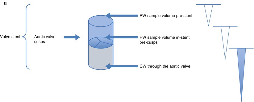
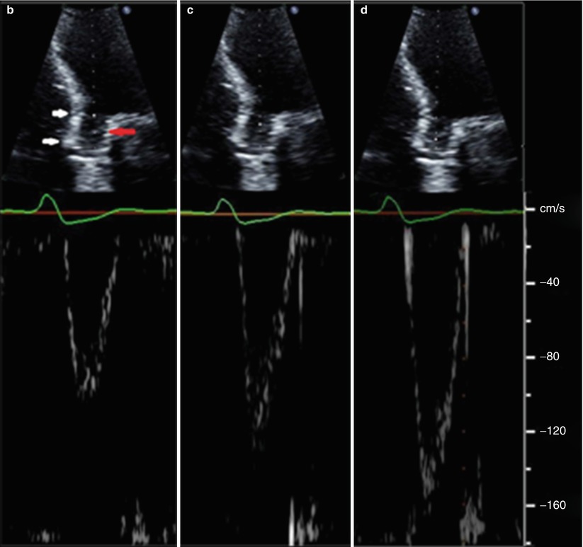
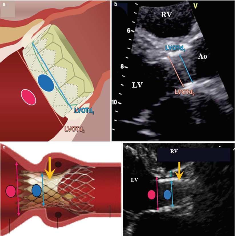
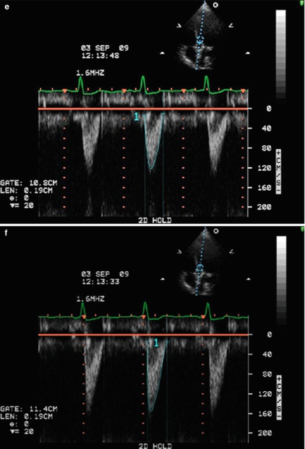
Fig. 36.10
Schematic and examples of spectral Doppler flow acceleration in a SAPIEN THV. Panel (a) Schematic presentation of echocardiographic pulse wave (PW) Doppler patterns when the sample volume is placed pre-stent, in-stent, but pre-cusps, and continuous wave (CW) through the aortic valve. Due to flow acceleration, it is generally recommended that the subvalvular velocities used in either Doppler velocity index or effective orifice area be sampled proximal to the stent. Panel (b) The PW Doppler pattern of a sample volume placed before stent. White arrows show the extent of the THV in the aortic root. Red arrow shows the level of the prosthetic aortic cusps. Panel (c) The PW Doppler pattern of sample volume placed within the stent but before cusps. Panel (d) The PW Doppler pattern of a sample volume placed at the level of the cusps
Fig. 36.11
 Transcatheter Aortic Valve Replacement: Current Evidence from Large Multicenter Registries
 Positron Emission Tomography Evaluation of Aortic Stenosis
 Pathologic Findings in Aortic Stenosis
 Transcatheter Aortic Valve Replacement in Patients with Chronic Kidney Disease: Pre-procedural Assessment and Procedural Techniques to Minimize Risk for Acute Kidney Injury
 Aortoiliofemoral Angiography and IVUS
 Valve-in-Valve for Transcatheter Aortic Valve Replacement: Do Imaging Requirements Change?


Schematic and examples of spectral Doppler flow acceleration in a SAPIEN THV. This figure shows the positioning of the pulse wave (PW) Doppler velocity acquisition and of the LV outflow tract (LVOT) diameter measurement at the pre- (pink oval and line) and in- (blue oval and line) stent locations for balloon- (Panels a and b) and self- (Panels c and d) expandable THVs. Panels (e) and (f) show the PW velocities at pre- and in-stent locations, respectively. It is recommended to measure the LVOT diameter and velocity at the present location except in cases where the position of the apical portion of the THV stent is low in the LVOT, which occurs more frequently with the self-expandable THVs. The yellow arrows indicate the location of the prosthetic cusps: the in-stent, pre-cusps segment of the valve is longer in self-expandable than in balloon-expandable THVs (Adapted with permission from [18]). Ao aorta, LV left ventricle, RV right ventricle
Related posts:
Transcatheter Aortic Valve Replacement: Current Evidence from Large Multicenter Registries
Positron Emission Tomography Evaluation of Aortic Stenosis
Pathologic Findings in Aortic Stenosis
Transcatheter Aortic Valve Replacement in Patients with Chronic Kidney Disease: Pre-procedural Assessment and Procedural Techniques to Minimize Risk for Acute Kidney Injury
Aortoiliofemoral Angiography and IVUS
Valve-in-Valve for Transcatheter Aortic Valve Replacement: Do Imaging Requirements Change?
Stay updated, free articles. Join our Telegram channel
Full access? Get Clinical Tree
