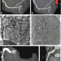
Fig. 2.1
Comparison of 16-row (Panel A) and 64-row CT coronary angiography (Panel B) of the right coronary artery (curved multiplanar reformation) in a 61-year-old male patient. 64-row CT shows longer vessel segments, especially in the periphery (arrow). This enhanced performance can be explained by fewer motion artifacts (due to breathing, extrasystoles, or variations in the length of the cardiac cycle) and the better contrast between arteries and veins resulting from the faster scan and consequently better depiction of the arterial phase. The improved depiction of the arterial phase using 64-row CT is also demonstrated in Fig. 2.2. Panel B also illustrates the slightly higher image noise with 64-row CT, which can be compensated for by the better depiction of the arterial phase and the higher intravascular density. Ao aorta
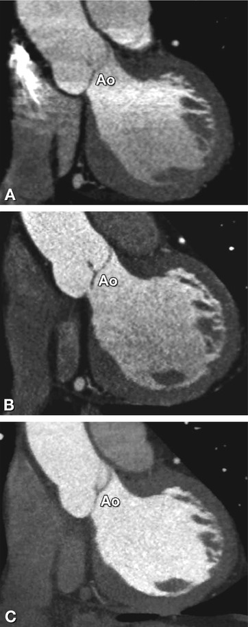
Fig. 2.2
The improved depiction of the arterial phase using 64-row CT (Panel B) and even further using 320-row CT (Panel C) when compared with 16-row CT (Panel A) is illustrated by a double oblique coronal slice along the left ventricular outflow tract, with the aortic valve nicely depicted (Ao). In the craniocaudal direction, the density in the aorta and left ventricle shows less variation and decline when 64 simultaneous detector rows are used (Panel C) and almost no difference with 320-row CT acquired during a single heartbeat. Use of 64- and 320-row CT thus improves image quality and facilitates the application of automatic coronary vessel and cardiac function analysis tools
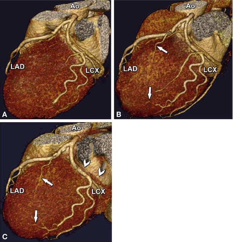
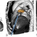
Fig. 2.3
Example illustrating the improved depiction of distal coronary artery branches using 64-row (Panel B) and 320-row CT (Panel C) in a 58-year-old female patient. Three-dimensional volume-rendered reconstructions of the left coronary artery with the left anterior descending (LAD) and left circumflex coronary artery (LCX) examined using 16-row (Panel A), 64-row (Panel B), and 320-row CT coronary angiography (Panel C). Note the improved depiction of smaller side branches with the 64-row (arrows in Panel B) and 320-row technology (arrows in Panel C) when compared with the same segments in 16-row CT (Panel A). Also, there is best depiction of the arterial phase (with less venous overlap, arrowheads in Panel C) using 320-row CT. Single-beat imaging using 320-row CT or second-generation dual-source CT with a fast prospective spiral also greatly reduces radiation exposure (Chap. 7). Ao aorta
Table 2.1
Typical characteristics of 16- and 64-row as well as single-heartbeat CT scanners
16-row | 64-row | Single heart beat CTa | |
|---|---|---|---|
Slice collimation | |||
Coronary arteries | 0.5–0.75 mm | 0.5–0.75 mm | 0.5–0.6 mm |
Coronary bypass grafts | 0.5–1.25 mm | 0.5–0.75 mm | 0.5–0.6 mm |
Gantry rotation time | |||
Coronary angiography | 0.4–0.6 s | 0.27–0.4 s | 0.28–0.35 s |
Scan length | |||
Coronary arteries | 9–13 cm | Increase by 15%b | 9–13 cm |
Coronary bypass grafts | 12.5–22 cm | Increased by 5–10% | 12.5–22 cmc |
Effective radiation dose | |||
Coronary arteries | 5–15 mSv | 10–20 mSvd | 1–5 mSv |
Coronary bypass grafts | 10–30 mSv | 20–40 mSvd | 2–10 mSv |
Contrast-to-noise ratio | |||
Coronary angiography | 15–25 | Similar | Similar |
Vessel lengths free of motion | |||
Coronary angiography | Improved by 10–30%e | Further improvements expected | |
Breath-hold time f | |||
Coronary arteries | 25–30 s | 8–12 s | 3 s |
Coronary bypass grafts | 40–50 s | 12–15 s | 5 s |
Contrast agent amount | |||
Coronary arteries | 90–130 ml | 60–90 ml | 40–70 ml |
Coronary bypass grafts | 130–160 ml | 80–110 ml | 50–80 ml |
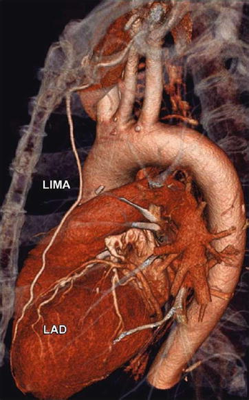
Fig. 2.4
Arterial bypass graft (left internal mammary artery, LIMA), which extends all the way down to the LAD and was scanned in less than 15 s, using a 64-row CT scanner. With this technology, preoxygenation is no longer necessary for bypass imaging. With 16-row technology, the scanning took an average of 40–50 s, and preoxygenation was almost always required. Note that CT nicely depicts the distance between the sternum and coronary bypass graft, which can be of relevance if repeat cardiac surgery is considered. Bypass imaging time can be further shortened with 320-row CT and second-generation dual-source CT (Table 2.1)
List 2.1. Technical requirements for cardiac CT
1.
CT scanner with at least 64 simultaneous rows
2.
CT scanner with a gantry rotation time of below 400 ms
3.
Adaptive multisegment reconstruction or dual- source CT
4.
ECG for gating or triggeringa of acquisitions
5.
Dual-head contrast agent injector for saline flush
6.
Workstation with automatic curved multiplanar reformation and three-dimensional data segmentation and analysis capabilities
a This refers to the acquisition method: retrospective (ECG gating) or prospective (ECG triggering). See Chap. 7 for details on radiation exposure reduction using ECG triggering
Temporal resolution can be significantly improved by using two simultaneous X-ray sources (dual-source CT, Siemens) and adaptive multisegment reconstruction (Toshiba, Philips, and GE). We believe that one of these two approaches should be implemented on cardiac CT scanners to reduce the influence of heart rate on image quality (List 2.1). In addition to these technical improvements, beta blocker administration should be used whenever possible to lower the heart rate to below approximately 60 beats per min, because slowing the heart rate to this level further improves both the image quality and the diagnostic accuracy (Chaps. 6


Stay updated, free articles. Join our Telegram channel

Full access? Get Clinical Tree


