Lynne S. Steinbach MD
Christine B. Chung MD
Hiroshi Yoshioka MD
The challenges associated with imaging the joints of the upper extremity include the inherent complexity of the anatomy encountered as well as the technical considerations related to the acquisition of the MRI study. The latter includes the magnetic field strength; coil selection; patient positioning; optimal imaging planes; sequences commonly used for routine shoulder, elbow, wrist, and hand studies; and the indications for MR arthrography in the shoulder, wrist, and elbow. The following discussion addresses the technical considerations relevant to the acquisition of MRI studies of the different upper extremity joints.
Magnetic Field Strength
In general, as the magnetic field strength increases, there is a linear increase in the signal-to-noise ratio (SNR) and contrast-to-noise ratio (CNR). The increased SNR results in shorter acquisition times and thinner slice thickness. This reduces the risk of patient motion and increases spatial resolution. The increased CNR determines the extent to which adjacent structures can be distinguished from one another as well as determining the general conspicuity of lesions on MRI studies. Clinical MRI is done on units ranging between 0.2 T and 3 T. Low-field imaging tends to be below 0.5 T. Between 0.5 T and 1.0 T is considered midfield imaging. High-field imaging is above 1.0 T.
High-field imaging at 1.0 T and above is preferred for upper extremity joint imaging. This is because low- and midfield imaging have less choice of pulse sequences and less SNR and CNR. Because imaging time has an inverse relationship to field strength, low- and midfield units take a significantly longer time for imaging, increasing the chance for motion artifact. The low-field magnet is attractive from an economic standpoint, costing less to purchase and maintain, reducing the cost per imaging study. There is also less artifact from metallic implants on lower field strength units, although this does not preclude imaging these devices on higher-field magnets.
For the shoulder, elbow, wrist, and hand, the low- and midfield extremity magnets can be useful to identify pathology that is noticeable without high resolution, including bone marrow signal abnormalities as might be seen with infection, tumor or large erosions, large tears of the tendons and ligaments, tenosynovitis, and soft tissue masses. Cartilage lesions and subtle tears of tendon, ligament, and fibrocartilage will not be well seen.
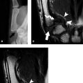
To date, studies comparing diagnostic accuracy and sensitivity of low-field versus high-field–strength systems have focused primarily on the shoulder and the knee with somewhat variable conclusions. Regarding the shoulder, several studies have reported no significant difference in sensitivity, specificity, and accuracy between low-field and high-field–strength systems for rotator cuff and labral lesions, although these studies were retrospective in nature and compared two different sets of patients, one imaged on a low-field strength system and the other on a high-field–strength system (1, 2). Another study, also retrospective, reported favorable sensitivity, specificity, and predictive values for low-field and high-field–strength systems with arthroscopy as a gold standard (3). Once again, however, the patient population studied on the low-field–strength system was not imaged on a high-field–strength system, but rather compared with studies from the literature. Magee et al. (4) prospectively evaluated a patient population with rotator cuff and labral pathology. The study design included imaging at low-field strength (0.2 T) and at high-field strength (1.5 T) with arthroscopy as the gold standard in the same patient population. Contrary to other studies, Magee et al. found that high-field–strength units allow more accurate interpretation than their low-field–strength counterparts and, perhaps most importantly, that the differences in interpretation did affect clinical treatment (Fig. 2.1). Another prospective study comparing low-field and high-field–strength imaging of rotator cuff and labral pathology suggested that diagnostic accuracy for small lesions of the rotator cuff and labrum encountered with low-field–strength studies was less than that of high-field–strength studies and could be enhanced by the addition of intra-articular injection of a gadolinium-based contrast material in conjunction with MRI (5).
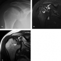
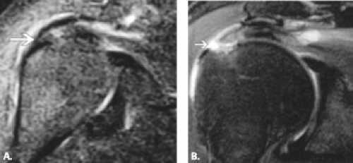 Figure 2.1 A 53-year-old man with shoulder pain. A: 0.2 T oblique coronal short tau inversion recovery MR image (TR = 2,500/TE = 22/IR = 75) shows abnormal signal in the distal supraspinatus tendon but no definite full-thickness tear (arrow). B: A 1.5-T oblique coronal fat-suppressed fast spin echo T2-weighted MR image shows that the supraspinatus tendon tear is full thickness as confirmed at arthroscopy. Reproduced with permission from Magee T, Shapiro M, Williams D. Comparison of high-field–strength versus low-field–strength MRI of the shoulder. AJR Am J Roentgenol. 2003;81:1211–1215. |
The body of literature relating to low-field–strength imaging of the elbow is quite limited, and for the finger, it is virtually nonexistent (6, 7). Although no study has directly compared low-field and high-field–strength imaging, the literature suggests that a dedicated low-field–strength MR system can distinguish between different patterns of chronic lateral epicondylitis (7). It is the opinion of the authors that MR images acquired on a high-field–strength system are preferable for detailed evaluation of the shoulder, elbow, and wrist and that low-field–strength studies should be reserved for screening purposes, if that choice exists. For the finger, the current body of literature does not even address the choice of low-field–strength imaging. Moreover, in many cases, optimal imaging has been achieved through the use of specially designed surface coils in conjunction with MRI at 1.5 T (8–12).
Clinical high-field imaging of upper extremity joints with 3-T MRI is growing (13, 14). The 3-T scanners are preferred for small field of view imaging as a result of increased resolution and higher SNR (15). Higher SNR has the potential to decrease imaging times and improve image quality. Decreased imaging time allows for increased patient throughput and reduces the possibility of patient motion. Small ligament and cartilage structures can be better evaluated on 3 T if the proper radiofrequency coils are available (13). These coils are slowly coming on the market, increasing the capability for joint imaging with 3 T (Figs. 2.2–2.7). Thinner slices are possible with 3 T. Study of the wrist at 3.0 T has demonstrated that the CNR increases by a magnitude of 2.0 to 2.9 times that of 1.5 T if all other parameters are kept constant (13). Disadvantages of 3-T imaging such as chemical shift and susceptibility artifacts can be reduced with increased readout bandwidth (64 kHz), keeping in mind that increased bandwidth reduces SNR and image quality. Chemical shift artifacts can also be reduced with fat suppression. Magnetic susceptibility artifacts can be a problem for imaging areas that contain orthopaedic hardware, because artifacts from hardware are increased at higher fields. Radiofrequency power deposition is also four times higher at 3 T. This can be offset with lower flip angle of refocusing pulses, shorter acquisition times, shorter TE, and shorter echo train length. Fat suppression and field inhomogeneity artifacts are reduced at 3 T. For extrapolating sequences from 1.5-T units, it is best to increase the TR to maximize SNR and decrease the TE as well as to maintain T1-weighted contrast equivalent to 1.5 T. TR is usually increased by approximately 20% from that used at 1.5 T.
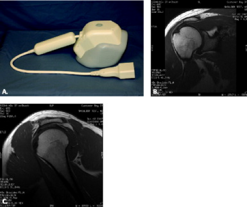 Figure 2.2 A: General Electric eight-channel, 3-T NeoCoil with examples. B: Coronal proton density and (C) sagittal T1-weighted images of the shoulder. Courtesy of Troy A Lewein, General Electric Healthcare. |
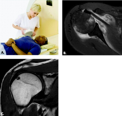 Figure 2.3 A: Philips work in progress 3-T, eight-channel, eight-element SENSE shoulder coil used on Open Intera or Achieva units with examples. B: Axial fat-suppressed proton density demonstrating synovitis and marrow contusions, and (C) coronal T1-weighted images showing a normal supraspinatus tendon with subchondral cyst formation. Courtesy of Laima Baltussis, Philips Healthcare. |
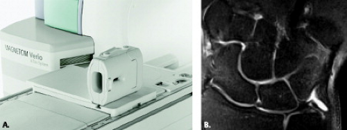 Figure 2.4 A: Siemens eight-channel, 3-T wrist coil used on the Open Magnetom Verio MR unit. B: Normal wrist using an eight-channel wrist coil (Invivo 8-channel wrist; proton density with fat suppression (field of view 8 cm, matrix 320, 0.26 × 0.26 × 2 mm). Courtesy of Milind Dhamankar, Siemens Healthcare AG. |
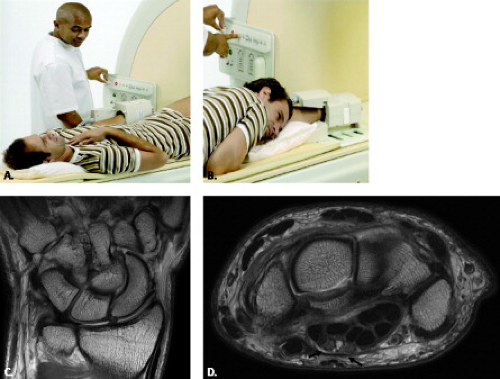 Figure 2.5 A: Philips SENSE wrist coil for 3-T, four channels, four elements with the patient’s arm at his side. B: With the patient in the superman position; (C) coronal proton density of a normal wrist; and (D) normal axial proton density image of the wrist at the level of the carpal tunnel. Notice the bifid median nerve (arrows). Courtesy of Laima Baltusis, Philips Healthcare. |
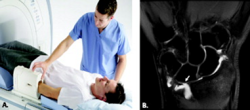 Figure 2.6 A: General Electric eight-channel, 3-T wrist coil, receive only. (B) Corresponding fat-suppressed proton density image of the wrist with a triangular fibrocartilage tear (arrow). Courtesy of Troy Lewien, GE Healthcare, and Larry Tanenbaum, Edison Imaging. |
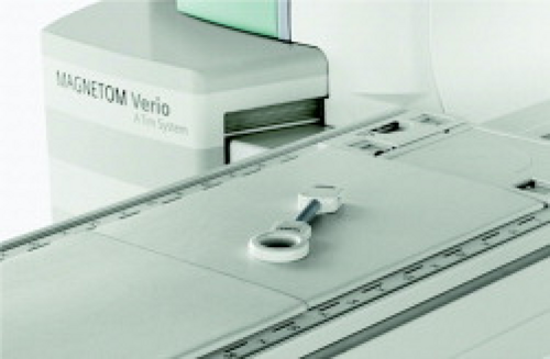 Figure 2.7 Siemens small field-of-view finger joint imaging for the Magnetom Verio, an open 3-T system. Courtesy of Milind Dhamankar, Siemens Healthcare AG, Germany. |
When performing MR arthrography on the 3-T systems, it is wise to dilute the ratio of gadolinium to a greater degree than is done for 1.5 T. The peak concentration at 3 T is 0.625 mmol/L compared with 1.5 T where it is 1.25 mmol/L (16). This means that dilution for 3 T is approximately 1:300 to 1:400 rather than 1:200 as is used for 1.5 T.
In the near future, joints will be imaged on even higher-field MR systems. Images of the wrist have been acquired at 8.0 T with an in-plane resolution of 100 to 140 μm.
Open and extremity MR units range from field strengths of 0.2 T to 1.5 T. These scanners provide a less confining space for claustrophobic patients in place of antianxiety medication and they also accommodate obese and very large patients. There is a role for these magnets for imaging of upper extremity joints, especially at higher field strengths. The open magnet also allows for provocative positioning of joints, which is occasionally helpful for diagnosis of disorders such as impingement of the shoulder. The extremity units are attractive because they can be sited in small spaces and are often less costly than the others. They are limited to the portion of the upper extremity below the shoulder and may be too long to accommodate elbows of smaller children. Field homogeneity can be unpredictable for fat suppression, but newer models are addressing that problem.
Coil Selection
Coils are available either from the manufacturer or a subcontractor. As a general rule, when using a radiofrequency coil, the size of the coil should be approximately 1.5 times the surface area to be imaged, allowing optimization of the SNR. There are many coil options for upper extremity joints, including dedicated wrist and shoulder coils, 5-inch receive-only surface coils, dual 3-inch coils, and the flexible wraparound coil (Figs. 2.2–2.8) (17–21). Quadrature and phased-array coils with multichannels allow for acquisition of high-resolution images of the joints.
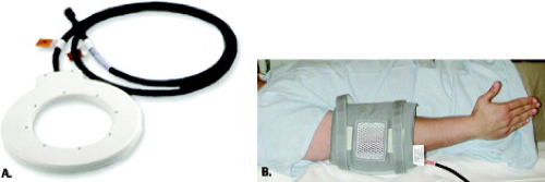 Figure 2.8 The 5-inch general purpose receive-only surface coil (A), and the General Electric flex receive-only coil (B) are among the choices for acquisition of MR images of the upper extremity, including the elbow. Images of the elbow can be obtained with the arm extended along the side with the hand in neutral position. Images courtesy of General Electric Healthcare. |
On certain machines, microscopy coils have become commercially available providing extremely high-resolution
images of the elbow and wrist when compared with conventional surface coils (22–24). The microscopy coil is commercially available at 1.5 T (Philips Medical Systems, Best, The Netherlands). There are two types of microscopy coil: 23 and 47 mm in diameter (Figs. 2.9 and 2.10). The microscopy coils produce high-resolution images with as low as a 5-cm field of view (FOV). They have integrated mini preamps, allowing for high-resolution MRI. Microscopy coils can be used for pediatric imaging; imaging of superficial vessels such as carotid plaques; skin imaging, for example, in invasive skin cancer; eye studies; and imaging of small joints such as the wrist and hand. One disadvantage of this kind of small coil is the limit on the area for signal production. The FOV provided by this coil is limited and does not allow analysis of the entire joint. Sometimes an area larger than the FOV of the microscopy coil is necessary to rule out a lesion outside the FOV. Therefore, in the clinical setting, combined use of small and large coils such as the synergy flexible coil (Fig. 2.10) is recommended.
images of the elbow and wrist when compared with conventional surface coils (22–24). The microscopy coil is commercially available at 1.5 T (Philips Medical Systems, Best, The Netherlands). There are two types of microscopy coil: 23 and 47 mm in diameter (Figs. 2.9 and 2.10). The microscopy coils produce high-resolution images with as low as a 5-cm field of view (FOV). They have integrated mini preamps, allowing for high-resolution MRI. Microscopy coils can be used for pediatric imaging; imaging of superficial vessels such as carotid plaques; skin imaging, for example, in invasive skin cancer; eye studies; and imaging of small joints such as the wrist and hand. One disadvantage of this kind of small coil is the limit on the area for signal production. The FOV provided by this coil is limited and does not allow analysis of the entire joint. Sometimes an area larger than the FOV of the microscopy coil is necessary to rule out a lesion outside the FOV. Therefore, in the clinical setting, combined use of small and large coils such as the synergy flexible coil (Fig. 2.10) is recommended.
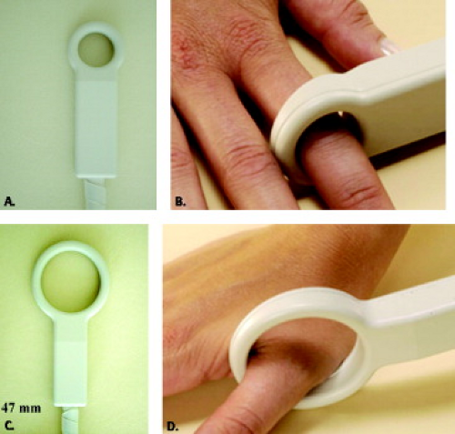 Figure 2.9 Philips microscopy coils. The 23-mm (A–B) and 47-mm (C–D) microscopy coils can be used to obtain high-resolution images of small areas. Courtesy of Philips Healthcare. |
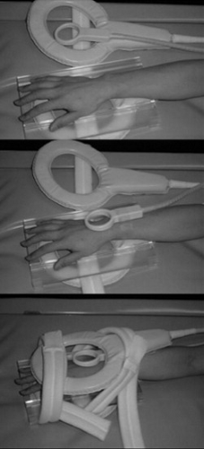 Figure 2.10 The microscopy coils used on the Philips units can be combined coil with other coils. This example shows a microscopy coil and a larger synergy flexible coil placed simultaneously to image the wrist with different fields of view without having to change coils during scanning. |
Shoulder
It is important to image the shoulder with a dedicated shoulder coil (Figs. 2.2, 2.3, and 2.11). Shoulder coils come in a variety of designs, including a custom-curved shape that molds to the rounded shoulder. Coils should also not be placed to medially and can be mounted on a platform to avoid respiratory artifact. The choice of coil depends on the manufacturer and field strength of the magnet. Challenges that affect shoulder MRI include inherent off-center magnet location of this joint with reduction in SNR and less homogeneous fat suppression.
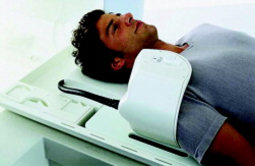 Figure 2.11 Siemens four-channel shoulder coil for the 3-T open system. Courtesy of Milind Dhamankar, Siemens Healthcare AG. |
Elbow
The acquisition of optimal MR images of the elbow is complicated by numerous factors, including difficulty with patient positioning, lower SNR at the off-center magnet, and the scarcity of dedicated elbow coils. The elbow can be imaged at the side or in the superman position (Figs. 2.8 and 2.12). A 5-inch wraparound coil is useful for elbow imaging. It is versatile and allows visualization of the articulation, including the attachment of the distal biceps tendon to the radial tuberosity, accommodating a wide range of elbow sizes. Elbow images acquired in the flexed position, however, necessitate the use of surface coils (see subsequent “Patient Position” section).
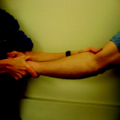
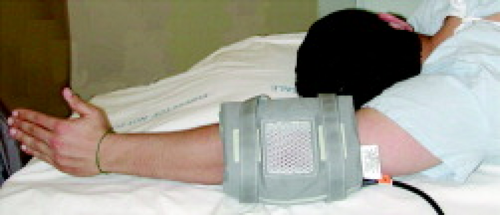 Figure 2.12 Superman position. The elbow is surrounded by a flexible wraparound coil and the arm is placed in the superman position. This position is achieved by placing the patient in a prone position with the arm extended over the head. This position can be uncomfortable for patients with shoulder injury. |
Wrist
Coil selection is also critical for high-resolution MRI of the wrist. A variety of coils can be used for wrist imaging such as a 3-inch surface coil, small radiofrequency transmit–receive, quadrature or multichannel phased-array wrist, and microscopy coils (Figs. 2.4–2.6, 2.8, and 2.10). Circular or flat coils (Fig. 2.8A) are useful for motion studies such as radial and ulnar deviation. When
imaging both wrists and/or hands, one can decrease scanning time by using a larger coil such as the extremity coil, placing both wrists and hands with palms against each other and arms above the head.
imaging both wrists and/or hands, one can decrease scanning time by using a larger coil such as the extremity coil, placing both wrists and hands with palms against each other and arms above the head.
Fingers
With regard to finger imaging, several options for coil selection have been introduced. These range from commercially available 3- to 5-inch receive-only surface coils and dedicated wrist transmit–receive coils as shown to specially designed dedicated transmit–receive saddle coils, local gradient coils, and combination local gradient with solenoid radiofrequency coils as shown in Figure 2.9 (8–12, 25–28). In many cases, the burden of finger MRI cases in a practice may not justify the purchase of a dedicated or specially designed finger
coil. In the experience of the authors, the 3- and 5-inch surface coils in conjunction with 1–T to 3-T imaging have the potential to produce high-quality diagnostic images.
coil. In the experience of the authors, the 3- and 5-inch surface coils in conjunction with 1–T to 3-T imaging have the potential to produce high-quality diagnostic images.
There is no question that advances in dedicated upper extremity coils allowing higher SNR and CNR will revolutionize MRI diagnostic capabilities in these joints.
Patient Positioning
Standard magnets offer limited alternatives for patient positioning when imaging the upper extremity joints. The small bore size and circumferential gantry of most closed systems necessitate that the joints be imaged with the patient supine and arm extended along the side. It is important to place foam pads or bolsters along the arm and in the coil to reduce motion.
Shoulder
For the shoulder, the patient is placed in a supine position with the shoulder and arm parallel to the body in neutral or mild external rotation (Fig. 2.13) (29–31). It is best not to include extreme external rotation because the biceps tendon is more difficult to follow and the fluid in the biceps tendon can blend in with the anterior lateral supraspinatus tendon to simulate a tendon tear (32). Internal rotation of the shoulder is not advocated for routine imaging because there is overlap between the supraspinatus and infraspinatus tendon as well as anterior capsular redundancy (32).
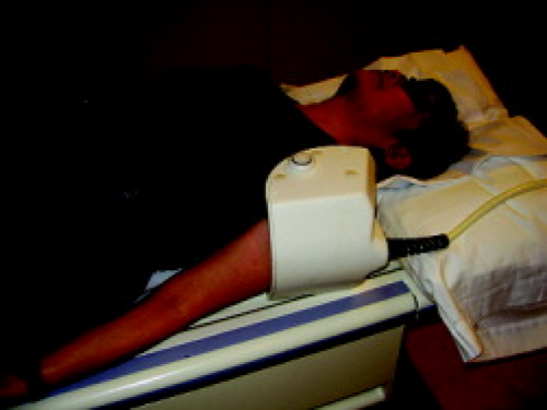 Figure 2.13 The patient is lying supine with a shoulder coil in place. The arm is at the patient’s side in mild external rotation. |
Additional provocative positions can aid in further evaluation of shoulder structures in certain situations. The diagnosis of superior labrum–anterior to posterior (SLAP) lesions is improved with arm traction (Fig. 2.14) (33). The wrist is pulled with a 3-kg nonferromagnetic weight. Other positions include abduction and external rotation (ABER) (Figs. 2.15 and 2.20) and adduction internal rotation (ADIR) (Fig. 2.21). These maneuvers can be done at the end or beginning of the study, preferably with MR arthrography.
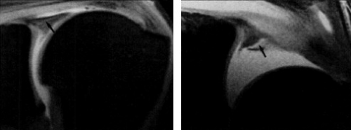 Figure 2.14 Cadaver of a 76-year-old man. A: MR arthrogram shows no definite labral tear. Note slightly increased signal intensity within the superior labrum (arrow) that was thought to represent possible fraying of the superior labrum. B: MR arthrogram with the arm in traction reveals a definite tear in the labrum. Note that contrast material extends into the tear (arrow). Reproduced from Chan KK, Muldoon KA, Yeh L, Boutin R, Pedowitz R, Skaf A, Trudell DJ, Resnick D. Superior labral anteroposterior lesions: MR arthrography with arm traction. AJR Am J Roentgenol. 1999;173:1117–1122. |
The ABER position is used primarily during MR arthrography to bring out subtle tears of the anteroinferior labrum such as the Perthes lesion. This position also opens the articular surface of the supraspinatus and infraspinatus tendon (34, 35). Patients with instability and suspected internal impingement can benefit from this assessment. The ABER position also has the potential to demonstrate scapulohumeral imbalance and decentering of the humeral head relative to the glenoid fossa. Decentering can occur in traumatic or atraumatic instability as well as glenohumeral osteoarthritis. Subtle shoulder subluxation not demonstrated with the arm at the patient’s side may be revealed in this position. The patient is positioned with the palm of the hand behind the head and neck. A coil is placed anteriorly over the region (Fig. 2.15). Coronal scout images demonstrate the humerus and glenoid. Cursors are drawn parallel to the long axis of the humerus (Fig. 2.16) to obtain oblique axial images of the glenohumeral joint (Fig. 2.17). More superior images are identified by the presence of the biceps tendon and the posterosuperior labrum (Fig. 2.18). Below these images one will see the supraspinatus tendon and midanterior labrum (Fig. 2.19). Inferiorly, further away from the biceps, the anterior inferior labrum and infraspinatus are seen (Fig. 2.20).
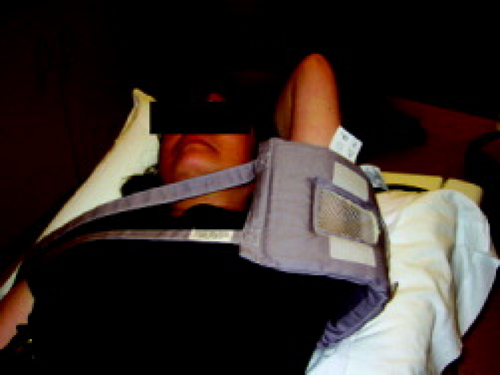 Figure 2.15 Abduction external rotation (ABER) position. The patient is supine. A coil is placed in the axillary region and the arm is positioned so that the palm of the hand lies behind the head and neck. |
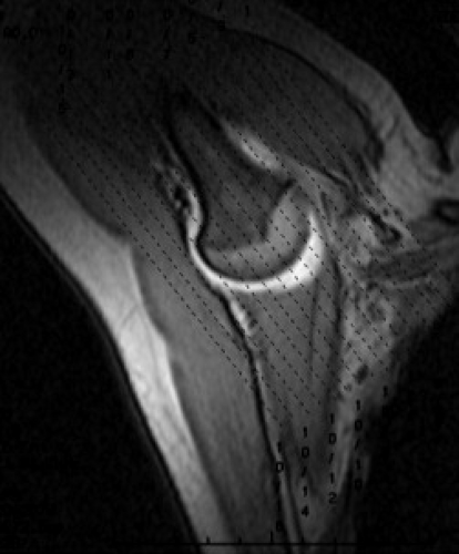 Figure 2.16 Abduction external rotation (ABER) scout. A localizer for oblique axial images for the ABER images represents a coronal scout of the area with cursors aligned along the long axis of the humerus. This results in oblique axial images of the glenohumeral joint. |
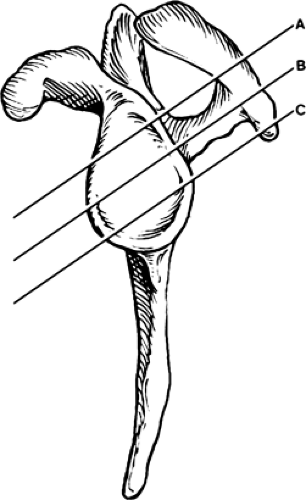 Figure 2.17 Abduction external rotation (ABER) orientation. ABER positioning results in oblique axial images along the glenoid. A: The superior portion of the glenoid, near the biceps anchor and supraspinatus tendon (Fig. 2.2.18). It also includes the posterosuperior labrum. B: The midportions of the anterior and posterior labrum and the junction between the supraspinatus and infraspinatus tendons (Fig. 2.2.19). C: The anterior inferior portion of the glenoid and the infraspinatus and teres minor tendons (Fig. 2.2.20). (See Chapter 3, Figure 2.15C.) |
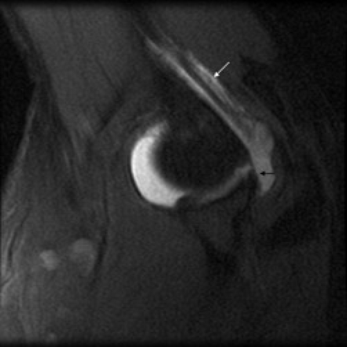 Figure 2.18 Normal superior abduction external rotation (ABER) MR image. ABER oblique axial image obtained in the superior portion of the glenoid labrum demonstrates the landmark biceps tendon (white arrow) and posterior superior labrum (black arrow). |
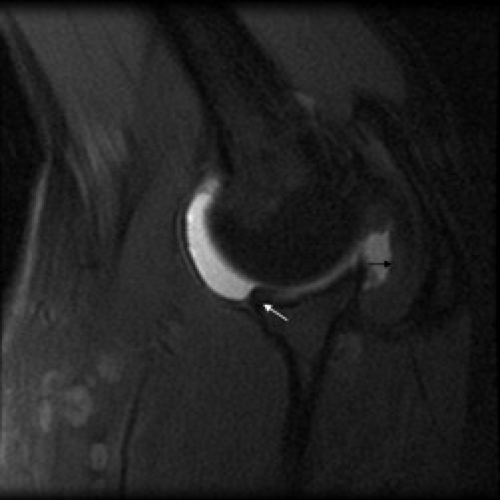 Figure 2.19 Normal mid-abduction external rotation (ABER) image shows the undersurface of the supraspinatus tendon (black arrow) and the anterior labrum (white arrow). |
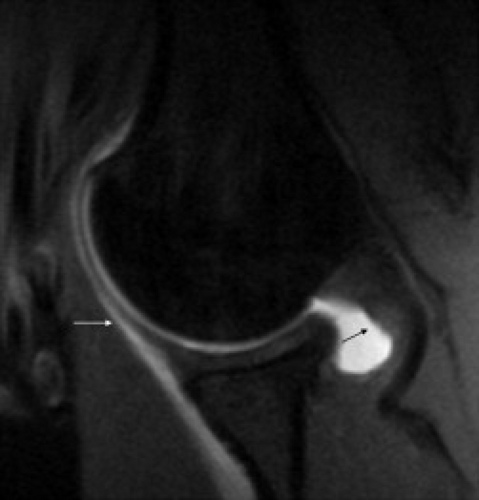 Figure 2.20 Normal inferior abduction external rotation (ABER) MR image. ABER oblique axial image obtained in the inferior portion of the glenoid labrum demonstrates that anterior inferior labrum being pulled by the inferior glenohumeral ligament (white arrow). The undersurface of the infraspinatus tendon is also visualized (black arrow). |
The ADIR position is more limited in scope but can be used to evaluate anterior labroligamentous periosteal sleeve avulsion (ALPSA) lesions of the anterior inferior labrum (36) (Fig. 2.21). In this position, the hand of the affected arm is placed behind the back.
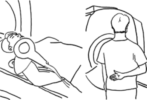 Figure 2.21 Adduction internal rotation (ADIR) position. ADIR position is obtained by placing the arm behind the back of the supine patient. A shoulder coil is placed in front of the region. Reproduced with permission from Song HT, Huh YM, Kim S, et al. Anterior–inferior labral lesions of recurrent shoulder dislocation evaluated by MR arthrography in an adduction internal rotation (ADIR) position. Song J Magn Reson Imaging. 2006;23:29–35. |
Although possible on a clinical MR unit, kinematic imaging is mainly done for research purposes. The shoulder can be positioned in internal and external rotation to assess anterior and posterior labral tears, respectively, and for assessment of subcoracoid impingement (37–39). An open magnet allows for dynamic abduction external rotation of the shoulder. The question remains as to the value of these additional sequences during clinical imaging time (40, 41).
Elbow
The small bore size and circumferential gantry of most closed systems necessitate that the elbow either be imaged with the patient supine, arm extended along the side, or with the patient prone, arm extended over the head, the so-called “superman position” (42) (Figs. 2.8A and 2.12). Each of these positions has advantages and disadvantages. Although the supine position is more comfortable for the patient, it does place the elbow outside the isocenter of the magnet making fat suppression, in some cases, suboptimal. The prone position moves the elbow away from the body and places the area of interest in the isocenter of the magnet, optimizing field homogeneity, but can be uncomfortable for the patient (43, 44).
Hand position during imaging of the elbow, primarily a hinge articulation with rotatory movement only in early and terminal flexion, is emphasized less than in the shoulder (45, 46). It has been suggested, however, that imaging of the elbow in full extension with the forearm and hand pronated can prove helpful for optimal visualization and assessment of the median and radial nerves (47). Many protocols use a supinated forearm position in the acquisition of MR images of the elbow(43, 44, 48, 49). In general, neutral positioning of the hand, achieved with the thumb pointed up, is usually the most comfortable for the patient and minimizes motion artifact. Whatever the hand and forearm position during imaging, care must be taken when placing grid lines to ensure image acquisition in the desired imaging plane.
An interesting alternative to imaging the elbow in the extended position is to image this articulation in flexion (47, 50, 51). Axial images in the fully flexed position have been shown to optimally evaluate the contents of the cubital tunnel and to provoke an ulnar nerve subluxation not demonstrated in the extended arm position (47). In this position, the distance from the medial epicondyle to the olecranon process is increased, the cubital tunnel retinaculum stretches, and the bulge of the medial head of the triceps muscle pushes the ulnar nerve anteriorly and slightly medially, resulting in reduction of the volume of the cubital tunnel (52, 53). Simplistically, the position of exaggerated elbow flexion is a provocative maneuver for the cubital tunnel and its contents.
Other authors have described imaging the elbow in 20 to 30 degrees of posterior angulation to optimally visualize the collateral ligament complexes (51) (Fig. 2.22). Imaging with posterior angulation or slight elbow flexion capitalizes on the slightly oblique course of the anterior band of the ulnar collateral ligament and radial collateral ligament as well as the pronounced obliquity of the lateral ulnar collateral ligament. Moreover, biomechanical studies have demonstrated that most of the fibers of the radial collateral ligament and the anterior band of the ulnar collateral ligament are taut with moderate flexion of the elbow (54).
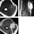
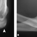
 Figure 2.22 Oblique coronal imaging plane. A: The coronal oblique plane can be achieved by placing localizer lines at 20 to 30 degrees angulation from the longitudinal axis of the ulna in the fully extended elbow. B: This plane allows visualization of the lateral ulnar collateral ligament (arrowheads) along its entirety. |
Another application and more specific description of MRI of the elbow in the flexed position has been introduced by Giuffre and Moss (50). The authors describe the “FABS” position, an acronym for Flexed Abducted and Supinated position of the arm during imaging (Fig. 2.23). The patient is imaged in the prone position with the elbow in the FABS position using either an extremity coil or a dedicated shoulder phased-array coil. A localizer is obtained in the coronal imaging plane. From that localizer, a sequence is planned along the long axis of the biceps tendon. If the biceps tendon is not readily visualized on the localizer image, the grid lines can be placed perpendicular to the radius. This results in the acquisition of an imaging plane that is axial to the forearm and coronal to the humerus. It is readily reproducible and allows excellent visualization of the biceps tendon at its full length allowing more facile delineation of high-grade partial from complete distal biceps tendon tears.
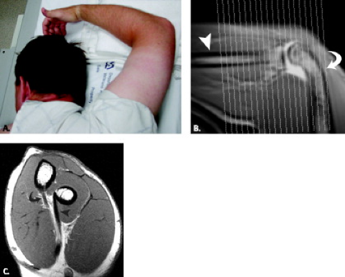 Figure 2.23 FABS (Flexion, Abduction and Supination) position. A: The FABS position is performed with the patient prone on the imaging table with the arm extended over the head flexed at the elbow with the forearm supinated. B: A coronal localizer is performed, and localizer lines are placed along the course of the biceps tendon (roughly approximated by paralleling the humeral shaft [curved arrow] and perpendicular to the radius [arrowhead]). C: Resultant images profile the distal biceps along its longitudinal axis [curved arrow] to its attachment on the radial tuberosity (arrowhead). |
Wrist
The wrist can be positioned in several ways, including with the patient supine and the arm at the side, in the superman position with the patient prone, or in the lateral decubitus position with the arm extended above the patient’s head (Figs. 2.5 and 2.6). Each position can pose challenges but generally yields good images.
Patients are generally most comfortable with the arm at the side if they can fit in the magnet bore with their wrist in the coil. Most of the time with the arm at the side, the fat suppression is uniform, but because the wrist is off-center, there can be more frequent inhomogeneity of the field producing spotty fat suppression.
After a period of time, pain may present in the shoulder when the patient is positioned with the arm above the head. The advantage of this position is the placement of the joint in the isocenter of the magnet, which produces more uniform fat suppression.
It is important to use restraints such as foam cushions and wedges as well as tape to make the patient more comfortable so that they can hold still and minimize motion. Excessive radial or ulnar deviation of the wrist should be avoided because this will change the radiolunocapitate alignment in the sagittal plane. At times, even correctly positioned wrists can simulate a dorsal intercalated segment instability (55). Therefore, it is important to correlate that finding with lateral conventional radiographs obtained with the wrist in neutral position.
Finger
The same challenge, with regard to off-center imaging, that exists in other upper extremity joints is encountered in the finger. Both the superman position and supine imaging with the arm along the side have been described in the literature with good image quality (8–12, 25–28). In general, the fingers are imaged in the fully extended position (Fig. 2.9). The finger can be taped along its course to ensure that this position is maintained through the duration of the imaging study (56). Imaging of the finger in the flexed position to evaluate possible pulley lesions as well as collateral ligament injury has been discussed in the literature (56–60) (Fig. 2.24). The flexed finger position can be obtained with the patient in the prone position, arm elevated with the hand resting on a flat board with the fingers flexed to approximately 45 degrees (56, 58, 61). Patient cooperation is required for the successful acquisition of images with a minimum of motion artifact in this situation.
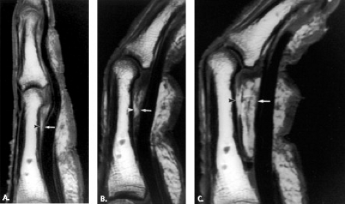 Figure 2.24 Finger flexion on a cadaver finger with pulley disruption. Sagittal T1-weighted spin echo (400/22) MR images obtained at (A) extension and (B) flexion and (C
Get Clinical Tree app for offline access
Related posts:Stay updated, free articles. Join our Telegram channel
Full access? Get Clinical Tree


|