Chapter 35 The fluoroscopic image
Chapter contents
35.1 Aim
Fluoroscopy is a technique that is widely used in radiography to produce images of moving structures. These can be used for real-time diagnostic imaging and treatment guidance. The aim of this chapter is to explain how fluoroscopic images are formed, concluding with a consideration of image quality and radiation dose issues. Traditionally the term fluoroscopy has referred to real-time imaging used for guiding procedures, while fluorography produces higher-quality images for organ investigations.
35.2 Fluoroscopic principles
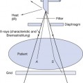
Phosphor materials are very widely used in radiography and need to have two key characteristics – the ability to strongly absorb X-rays and the ability to convert a percentage of this absorbed energy to visible light. X-ray absorption (by the photoelectric absorption process) is improved by the presence of high atomic number elements like caesium, barium, iodine and the ‘rare earths’. These all typically have K-shell absorption edges at about 30–35 keV, which are well placed to absorb X-rays produced at about 70–100 kVp (see Ch. 23).
The overall luminescent radiant efficiency (conversion rate of X-ray energy to light energy) is normally only about 10–20% for phosphor materials. This means that considerable intensities of X-rays are needed to produce enough light for a glowing fluoroscopic image to be viewed directly (without any amplification), even in a darkened room. In the first half of the twentieth century, imaging department staff had to do exactly this; view a phosphor screen directly during fluoroscopic procedures, with patient and staff receiving large radiation doses in the process.
35.3 The image intensifier
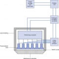
The traditional X-ray image intensifier involves various energy changes between the input and output phosphors of the device, as shown in Figure 35.1.
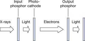
Table 35.1 indicates the relative numbers of photons or electrons arising at each stage of the process of image intensification.
Table 35.1 Approximate relative numbers of photons or electrons arising at each stage of the image intensification process
| TRANSFORMATION | NUMBERS OF RESULTANT PHOTONS OR ELECTRONS |
|---|---|
| 1 X-ray photon absorbed in the input phosphor | ≈2×10³ light photons are emitted by the input phosphor – of these, about half are absorbed in the phosphor material |
| ≈1×10³ light photons strike the photocathode | ≈2×10² electrons are emitted by the photocathode |
| ≈2×10² electrons are accelerated and strike the output phosphor | ≈1×10⁵ light photons are emitted by the output phosphor |
Related posts:
Stay updated, free articles. Join our Telegram channel

Full access? Get Clinical Tree


