Key Points
- ▪
The components of the left and right-sided mediastinal and cardiac silhouettes should be committed to memory in detail, as should the frontal projections and the locations and orientations of the cardiac valves on the frontal radiographic projection of the heart.
- ▪
There are signs of specific chamber enlargement that have varying sensitivities and specificities, but that overall are useful, with the caveat that most signs are predicated on the presence of single chamber enlargement and a normal chest a cavity. Multiple chamber enlargement complicates the assessment of single chambers.
Cardiovascular Silhouettes
Cardiovascular structures that are visible on the chest radiograph owe their visibility to being bordered by air-inflated lung. The difference in radiographic attenuation of aerated lung versus the cardiac or vascular structure results in an often very well-defined visually apparent boundary. The greater the attenuation difference of the two tissues that form an interface, the greater the radiographic definition of the interface and the greater the clarity and distinction of the silhouette. Hence, the border of a cardiac chamber against lung is readily apparent. Such a margin of a cardiac or vascular structure is referred to as “border forming” and results in a silhouette, many of which are recognizable. Think of Alfred Hitchcock, whose unique silhouette became his logo.
Conversely, if the other walls of the cardiac chamber are adjacent to other cardiac chambers of equal attenuation, then the boundary of the two cannot be determined by the chest radiograph. Hence, non–border-forming regions of the heart are inapparent radiographically. Alternative imaging modalities, particularly the tomographic ones (echocardiography, computed tomography, and magnetic resonance imaging), are the most reliable means of measuring true chamber dimensions.
Accumulation of high attenuation tissue adjacent to the heart (consolidated lung, pleural effusion, intrathoracic mass) results in loss of silhouettes and their usefulness as signs.
It is through the understanding of which cardiac or vascular structure is responsible for which specific silhouette curves on the chest radiograph that one achieves an understanding of which cardiac or vascular structure is enlarged or displaced and therefore causing the curvature. Hence, a comprehensive understanding of which cardiac or vascular structure is enlarged or displaced and therefore causing the curvature is an essential prerequisite to reading and understanding chest radiographs, because interpretation of the chest radiograph is based on silhouette recognition. Although silhouette recognition as a means of identification can never be as obvious and accurate as having full tomographic rendering, it is surprisingly useful, and more rapidly and widely available than tomographic methods such as echocardiography, cardiac MRI, or cardiac CT.
Normal Right-Sided Silhouettes
From superior to inferior, the silhouettes are ( Graphic 2-1 ; Fig. 2-1 ) as follows:
- □
Superior vena cava: The superior vena cava normally forms most of the right superior border of the cardiovascular structures in the chest.
- □
Azygous arch: The distal arch of the azygous vein, where it arches anteriorly at and over the right tracheobronchial angle, is often behind the superior vena cava and, unless enlarged, is not readily visible in normal patients (see Graphic 2-1 ). Normally, it is less than 1.0 cm in size with the patient standing, and less than 1.3 cm in size with the patient supine. The size of the azygous vein is determined by the central venous pressure. In 5% of the population, the azygous vein resides more laterally and superiorly in the azygous fissure.
- □
Right pulmonary artery: The diverging right pulmonary artery crosses the border formed by the superior vena cava.
- □
Right pulmonary veins: The converging right pulmonary veins are inferior to the right pulmonary arteries.
- □
Right atrium: The right atrium normally forms a well defined border and appears as a gentle, nearly flat curve. Most of the right inferior border of the cardiopericardial silhouette (CPS) is formed by the right atrium.
- □
Inferior vena cava: A small portion of the inferior vena cava is usually revealed on the frontal radiograph, but generally only with deep inspiration.
- □
Right cardiophrenic junction (where the cardiac silhouette joins the diaphragmatic silhouette): This may be formed by either the inferior vena cava, or, more commonly, by a fat pad.


Normal Left-Sided Silhouettes
From superior to inferior, the silhouettes are (see Graphic 2-1 ) as follows:
- □
Left subclavian artery: The left subclavian artery forms the border of the left superior mediastinum as seen on the chest radiograph. The curve should be gentle and gradual. If the left subclavian artery has an exaggerated curve, underlying possibilities include elongation/dilation from hypertension, from hypertension secondary to coarctation of the aorta, and atherosclerosis. If the contour in the vicinity of the left subclavian artery is more vertical and straight than usual, then persistence of a left superior vena cava is likely.
- □
Aortic “knob”: The “knob” of the aorta is a term that refers to the distal aortic arch/proximal descending aorta that resides below the left subclavian artery. The term is obviously a misnomer because there is not normally a protruding “knob” to the aorta, but the term is forgivingly used. This silhouette is visible on every normal chest radiograph. The normal diameter of the aorta averages 2 cm in this region but may be up to 3 cm in larger individuals. The trachea is mildly displaced to the right side by the arch of the aorta. A small bump or nipple is evident on the lateral aspect of the aortic “knob” in a minority of patients; this is caused by the left superior intercostal vein. Prominence of this vein results from elevated central venous pressure ( Graphic 2-2 ).

Graphic 2-2
The location of the left superior intercostal vein may be apparent on a frontal radiograph as a nipple-shaped silhouette on the lateral aspect of the aortic arch.
- □
Aortic pulmonary window: Beneath the aortic “knob,” and above the pulmonary artery, there is normally an abrupt indentation with the inferior margin aorta forming the upper border and the superior margin of the pulmonary artery forming the lower border. Within this space (the aorticopulmonary window), multiple important structures reside—the ductus/ligamentum arteriosus, the left recurrent laryngeal nerve, and the ductus lymph node(s), as well as fat. Compromise of this space (by enlargement of the aorta, the left atrium lymph nodes, or a ductal diverticulum) may result in compression of the left recurrent laryngeal nerve. Aerated lung between the aortic arch and main pulmonary artery is a sign of absence of the pericardium.
- □
Main pulmonary artery: Inferior to the aorticopulmonary window is the main pulmonary artery, which is well-defined against the left lung. The main pulmonary artery arches over the left main bronchus, slightly above the level of the left pulmonary artery bifurcation. Normally, the silhouette of the left side of the main pulmonary artery is slightly convex.
- □
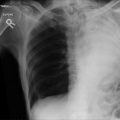
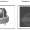
Left atrial appendage: On the frontal radiograph, the only portion of the left atrium that can normally be seen is a small portion of the left atrial appendage. The appendage lies under the main pulmonary artery and above the CPS border formed by the left ventricle. Normally, the curvature of the appendage is mildly concave, because it is normally nearly empty ( Fig. 2-2 ). Straightening or bulging of the left atrial appendage silhouette strongly suggests left atrial enlargement/dilation but also may be caused by the presence of mass lesions.

Figure 2-2
Contrast-enhanced computed tomography scan, coronal image approximately at the plane corresponding to the posteroanterior chest radiograph. The structures that generate the left mediastinum and left heart border silhouettes are apparent (from superior to inferior) as follows:
- •
Left subclavian artery (note the excess contrast effect and the artifacts arising from injection into a left arm vein)
- •
Distal aorta (“knob”)
- •
Main pulmonary artery
- •
Left atrial appendage (more obvious in this case than usual)
- •
Left ventricular lateral anterolateral wall
- •
- □
Left ventricle (LV): Most of the left border of the heart is normally formed by the left ventricle, although only 10% of the frontal CPS area is normally occupied by the left ventricle. The left ventricular border runs as a smooth continuation of the border formed by the left atrial appendage. Lengthening of the left ventricular border is consistent with lengthening of the left ventricle, a sign of enlargement.
- □
Left cardiophrenic junction (where the cardiac silhouette joins the diaphragmatic silhouette) is usually formed by the left ventricle and is less commonly formed by a fat pad ( Fig. 2-3 ).

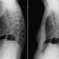
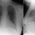
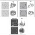
Figure 2-3
Coronal computed tomography scans revealing the right and left heart as well as the right and left mediastinal silhouettes. On the left upper image, the superior vena cava and right atrial contributions to the right-sided silhouettes are apparent, as are the aortic arch, main pulmonary artery, and left ventricle along the left heart border. The slight indentation of the left heart border at the angle between the main pulmonary artery and the left ventricle is also apparent. On the left lower image, on a slightly deeper plane, (part of) the left atrial appendage is normally present between the main pulmonary artery and the left ventricular anterolateral wall. On the right upper image, on yet a deeper plane, the body as well as the tail of the appendage can be seen, under the left upper pulmonary vein, now deep to the pulmonary artery. As well, the supradiaphragmatic portion of the inferior vena cava is also visible, now deep to the right atrial freewall. On the right lower image (thick maximum intensity projection view), the right coronary artery is seen, yielding the discrimination of the right atrium and right ventricle on the frontal plane image.
Normal Non–Border-Forming Structures on the Frontal Chest Radiograph
- □
Right ventricle: The right ventricle is not CPS border-forming on the frontal chest radiograph, although it typically occupies 70% of the anterior projection of the heart.
- □
Left atrial body (left atrial appendage excluded): The body of the left atrium is posterior and therefore does not form an edge border of the CPS, but it is evident in most individuals as a silhouette medial to the right atrial border. The reason that the left atrium forms a silhouette separate from the right atrial silhouette is that both structures abut lung tissue, with the left atrium lying posteriorly and superiorly, and the right atrium lying laterally, anteriorly, and inferiorly, as each atrium protrudes separately posteriorly in a slightly bulbous fashion.
- □
Ascending aorta: Normally, the lateral border of the ascending aorta lies medially to the lateral border of the superior vena cava, and is therefore not radiographically apparent. When the root and/or ascending aorta dilate, however, they may assume the lateral border and overlay the right hilum, obscuring it. This is an important sign of ascending aortic enlargement.
Signs of Cardiac Chamber Enlargement on the Frontal Chest Radiograph
The following discussion about particular radiographic signs and their association with specific chamber enlargement is predicated on enlargement of solely or primarily one chamber or structure. When any chamber enlarges substantially, the position, orientation, and radiographic appearance of the other chambers, and even blood vessels, may be altered. Hence, displacement of a cardiac border does not necessarily imply enlargement of the adjacent chamber. When more than one cardiac chamber enlarges substantially, the positions and orientations of all of the cardiac chambers may become altered in a more complex fashion. Many forms of heart disease, particularly valvular and myopathic, result in multichamber enlargement.
Consider the case of right heart enlargement from an atrial septal defect. Enlargement of the right ventricle rotates the heart to the left (when viewed from the patient’s head), causing the aortic arch to fold on itself (looking smaller on the frontal chest radiograph) and the main pulmonary trunk to rotate and appear more prominent. The enlarged right ventricle may actually assume the left heart border (which is normally formed by the left ventricle).
When assessing the chest radiograph for signs of chamber enlargement, another consideration is that chest cavity configuration may play into the orientation and radiographic appearance of chamber enlargement. For example, some patients have a narrow anteroposterior (AP) chest cavity dimension. Cardiac chamber enlargement may have to occur more laterally than anteroposteriorly, and posteroanterior (PA) chest radiography suggests more enlargement than there truly is. On the lateral chest radiograph, such patients may be seen to have a greater degree than normal of apposition of sternum to the anterior cardiac surface, falsely suggesting right ventricular enlargement. Conversely, patients with large AP chest cavity dimensions (e.g., some patients with obstructive lung disease) have increased retrosternal airspace on the lateral chest radiograph, which makes the right ventricle appear smaller than it truly is.
In summary, application of standard radiographic criteria for chamber enlargement loses merit in the following conditions:
- □
Multiple chamber enlargement
- □
Abnormal chest cavity configuration
- □
Abnormal diaphragm position
- □
Gross anatomic variations where the structures are malpositioned
- □
Masses or processes that displace or rotate the mediastinum
There are no perfect radiographic signs of chamber enlargement. In general, the more signs that a chamber is enlarged, and the more obvious the radiographic findings, the greater the probability that the chamber is enlarged.
Enlargement of the Left Ventricle
Enlargement of the left ventricle ( Graphic 2-3 ) occurs because of infarction, cardiomyopathy, pressure (hypertension, aortic stenosis) or volume (aortic or mitral insufficiency) overload, high output states (anemia, pregnancy), or a combination of these conditions.
- □
The left ventricle enlarges along three axes into three dimensions:
- •
Inferiorly (somewhat suggested on the PA radiograph)
- •
Posteriorly (apparent on the lateral radiograph)
- •
Laterally (apparent on the PA radiograph)
- •
- □
The predominant direction of where enlargement of the left ventricle occurs is somewhat different among patients, and it depends on the contour of the patient’s diaphragm and the size and shape of the heart. A large gastric air bubble often highlights the extent of the heart, particularly the left ventricle, that lies beneath (posterior, inferior, and lateral to) the dome of the diaphragm.
- □
Early signs of left ventricular enlargement include lengthening of the left heart border (from the pulmonary artery segment to the apex). More advanced left ventricular enlargement often leads to clockwise rotation (as seen from the head) of the heart.
- □
The shape of the enlarged left ventricle depends to some extent on the cause of the enlargement. Mitral and aortic insufficiency (classic volume overload states) are said to enlarge the left ventricle proportionally more along its long axis. In myocardial disease (as with coronary artery disease and cardiomyopathies), the left ventricle enlarges proportionally more along its short axis, therefore causing the left ventricle and thereby the CPS to become more globular.
- □
Concentric left ventricular hypertrophy per se cannot be reliably identified or excluded from chest radiography findings. Most commonly, concentric left ventricular hypertrophy occurs at the expense of the cavity until later in the disease stage when the cavity may dilate. Thus, until the late stages of the disease, the left ventricular cavity is not enlarged, and therefore the CPS is little altered. Left ventricular hypertrophy may lead to rounding of the left heart border, increasing the transverse cardiac diameter by up to 0.5 cm. The dimensions of the heart also vary as well though by 0.5 to 1.0 cm through the phases of the cardiac cycle.