Thoracolumbar Spine Checklists
 1
1
Imaging assessment
Radiographic examination
AP
Lateral views
Computed tomography (CT)
Axial
Reformatted images
Coronal
Sagittal
3-D
 2
2
Anatomic features, biomechanics, and forces of injury
Anatomy
Biomechanics
Denis three-column concept
Forces of injury
Flexion
Extension
Compression
Distraction
Shearing
Rotation
 3
3
Common forms of fracture and fracture-dislocations in adults
Fracture
Vertebral body
Anterior wedged compression
Burst
Chance (seat-belt)
Flexion-distraction
Extension
Vertebral appendage
Transverse process
Spinous process
Fracture-dislocation
Shearing
Flexion-distraction
 4
4
Multilevel spinal injury
Definition
Multiple spinal fractures at discontiguous levels
Incidence dependent on means of examination
Radiography 5% to 7%
CT 15% to 20%
MRI up to 50%
Patterns of primary and secondary injuries
Upper cervical spine and lower cervical spine
Lower cervical spine and lumbar spine
Thoracolumbar junction and lower lumbar spine
Mid-thoracic spine and cervical and/or lumbar spine
Importance of imaging entire spine
 5
5
Common sites of injury in the elderly
- A.
Osteoporosis
Dowager’s hump
Codfish vertebra deformity
Acute fractures
- B.
Pathologic fractures
Differentiate from osteoporotic fractures
 6
6
Fractures in the ankylosed spine
Diffuse idiopathic skeletal hyperostosis (DISH)
Ankylosing spondylitis
 7
7
Common sites of injury in children and adolescents
SCIWORA (spinal cord injury without radiographic abnormality)
Anterior wedged compression fractures
Flexion-distraction and Chance (seat-belt) fractures
Apophyseal ring avulsions
 8
8
Injuries likely to be missed
Spinal radiographic examination obtained for significant trauma and not CT
CT is more sensitive than radiography in disclosure of fractures.
Radiographs fail to disclose 10% to 20% of fractures shown on CT.
Second-level injury in multilevel spinal injuries
Must obtain CT of the remainder of spine once a significant spinal fracture is found
Subtle widening of disc space in distraction or hyperextension injuries is overlooked.
Need to examine interspaces closely and compare with adjacent interspaces to avoid oversights
Transverse process fractures
In most cases just failed to look specifically at transverse processes for fractures
Make it a point to examine transverse processes specifically in every case.
 9
9
Where else to look when you see something obvious
| Obvious | Look for |
|---|---|
| Anterior wedged compression fracture | R/O burst fracture |
| Fragment of vertebral body into spinal canal | |
| Wide interspinous distance | |
| Sagittal fracture vertebral body | |
| R/O flexion-distraction fracture | |
| Horizontal fracture of posterior elements | |
| Separation of spinous processes | |
| Fracture of one vertebra | Similar fracture of contiguous vertebrae |
| Second-level discontiguous fracture | |
| Vertebral body fracture in elderly | R/O metastatic disease |
| Destruction of cortex | |
| Pedicle sign | |
| Paraspinous soft tissue mass |
 10
10
Where to look when you see nothing at all
If presented with radiographs of spine
Determine nature of injuring forces; if sustained significant injury, CT examination is required.
Re-evaluate radiographic examination looking for evidence of subtle fx.
If any question concerning above, obtain CT examination of spine.
If presented with CT examination
If sustained neurologic injury, obtain MRI.
If no visible fracture or dislocation but has significant pain or inability to bear weight, obtain MRI.
Obtain MRI to disclose occult fx.
Thoracolumbar Spine – The Primer
 1
1
Imaging assessment
Radiographic examination
AP
Lateral views
Computed tomography (CT)
Axial
Reformatted images
Coronal
Sagittal
3-D
Imaging techniques
In the setting of blunt trauma with suspected thoracolumbar spine injury, CT is recommended by the American College of Radiology (ACR) as part of the initial trauma workup in adults.
Clinical criteria that warrant thoracolumbar spine imaging include the following 1 :
Back pain or midline tenderness
Local signs of thoracolumbar injury
Abnormal neurological signs
Cervical spine fracture or known cervical injury
GCS <15
Major distracting fracture
ETOH/drug intoxication
Rigid spine disease
In general, the thoracolumbar spine imaging with dedicated sagittal and coronal reformats of the spine can be provided from the CT chest, abdomen, and pelvis without need for additional dedicated spine CT imaging. In children <14 years CT of the thoracolumbar spine may be considered if there is a high clinical suspicion for injury, and either x-rays or CT may be indicated if a known cervical spine fracture is present. MR is clearly indicated for patients with neurologic abnormalities and may be required for evaluation of the discoligamentous complex.
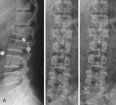
Radiography
Radiography was long the mainstay of imaging the potentially injured spine but has now, in large measure, been replaced by CT. Still many radiographic examinations of the thoracolumbar spine are obtained in order to “clear” the spine in patients who are thought to have little chance of a spinal fracture, in the opinion of the examining physician on the basis of the patient’s history and physical examination. AP and lateral views of the thoracolumbar spine are sufficient for this purpose ( Fig. 7-1 ). However, if there is any question of an abnormality, a CT examination is required for proper evaluation.
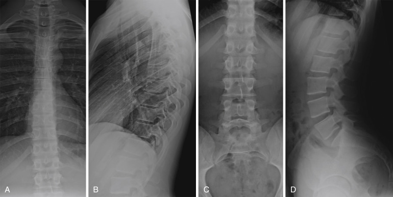
The examples shown of normal AP and lateral radiographs of the thoracic and lumbar spines were obtained under ideal conditions on patients without a history of trauma. The spinal radiographs of those who have sustained significant trauma are often less satisfactory due to limitations of positioning and patient motion. The spine is much better seen on CT.
CT. Multidetector CT (MDCT) with routine, excellent, immediately available image reconstructions in both the coronal and sagittal planes is now the mainstay of imaging spinal trauma. CT has proven to be much more sensitive than radiography in the detection of spinal injuries; CT reveals fractures that are not apparent on radiographs and significantly more fractures in patients with fractures shown by radiography.
Thin section axial slices are obtained, and images are reconstructed in the coronal and sagittal planes. The thoracic and lumbar spine must be examined in its entirety. Once a significant fracture or dislocation of the spine has been identified, it is important to examine the remainder of the spine to exclude the presence of other spinal injuries. CT of the entire spine is performed to clear the spine in obtunded patients.
CT examination: minimum necessary
Axial, sagittal, and coronal noncontrast images in bone algorithm
Axial and sagittal images in a soft tissue algorithm
Having a well-defined and consistent search pattern for thoracolumbar spine evaluation will allow for rapid identification and classification of spinal injuries. While the pattern of search varies among readers, the following minimum elements should be included.
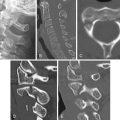
Sagittal CT search pattern
- •
Right lateral facet alignment and facet fractures ( Fig. 7-3 A )
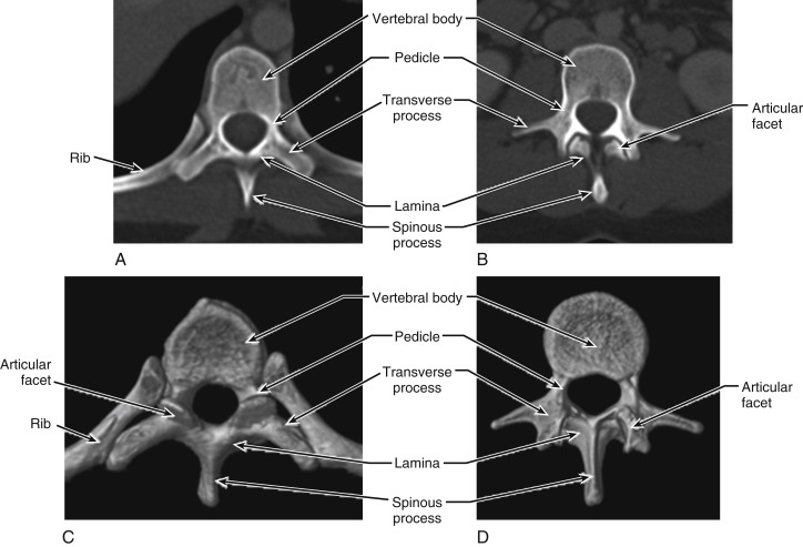
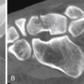
FIGURE 7-2
Anatomic features on axial CT: ( A ) normal thoracic spine vertebral body; ( B ) normal lumbar spine vertebral body; ( C ) normal thoracic spine vertebral body; ( D ) normal lumbar spine vertebral body.
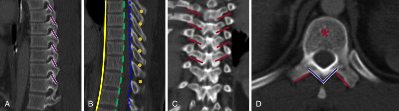
FIGURE 7-3
Sagittal CT search pattern: ( A, B ) coronal search pattern; ( C ) axial CT search pattern; soft tissue windows ( D ).
- •
Anterior spinal line and vertebral body heights ( Fig. 7-3 B )
- •
Posterior spinal line ( Fig. 7-3 B )
- •
Spinolaminar line ( Fig. 7-3 B)
- •
Interspinous distances and posterior spinous processes ( Fig. 7-3 B )
- •
Left lateral facet alignment and facet fractures ( Fig. 7-3 A, B )
Coronal search pattern
- •
Vertebral body for fractures (not shown)
- •
Transverse processes ( Fig. 7-3 C, D )
- •
Posterior spinous process (not shown)
Axial CT search pattern
- •
Vertebral body for fractures ( Fig. 7-2 A-D )
- •
Transverse processes ( Fig. 7-2 A-D )
- •
Posterior arch with laminae ( Fig. 7-2 C, D )
- •
Posterior spinous process ( Fig. 7-2 C, D )
Soft tissue windows
- •
Prevertebral soft tissues
- •
Paraspinous musculature for edema/hemorrhage
- •
Spinal canal for disc protrusions, epidural hematoma, fragments
MRI
The principal limitation of CT is the inability directly to visualize the spinal cord and supporting ligamentous structures of the spine. However, these limitations can now be overcome with the use of MRI, which is ideally suited to evaluate the status of these vital structures. While not as yet used routinely in the assessment of spinal injuries, MRI is obtained in those patients with neurologic deficits to assess the status of the spinal cord and determine the source of the neurologic deficit. MRI is not acquired acutely but rather is delayed until the patient is clinically stable. An examination of the entire spine should be performed to exclude or identify the relatively common associated discontiguous spinal injuries that may be present in such cases. MRI is also obtained in selected cases to assess the status of spinal ligaments prior to surgical intervention.
Magnetic resonance (MR) evaluation
While indications for MR imaging in the thoracolumbar spine have expanded in recent years, MR remains a complementary modality to CT in imaging of acute spinal trauma, as CT remains the mainstay for rapid fracture evaluation and trauma. MR remains highly indicated in patients with neurologic abnormalities, as a complementary modality to CT. A comprehensive review of thoracolumbar spine MR is beyond the scope of this primer, but a few key findings that should be included in the search pattern will be discussed with the individual injury types below.
Routine thoracolumbar spine MRI should include the following sequences, at a minimum:
- •
Sagittal T1
- •
Sagittal FSE T2
- •
Sagittal STIR or T2 fat-saturated images
- •
Axial T1
- •
Axial T2
 2
2
Anatomic features, biomechanics, and forces of injury
Anatomy
Biomechanics
Denis three-column concept
Distribution of fractures
Forces of injury
Flexion
Extension
Compression
Distraction
Shearing
Rotation
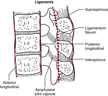
Ligamentous anatomy of spine
The principal spinal ligaments are the anterior and posterior longitudinal ligaments, the ligamentum flavum, and interspinous and supraspinous ligaments ( Fig. 7-4 ). The integrity of these structures is essential for maintenance of spinal stability.
Biomechanics of spinal injury
Denis proposed a three-column concept of the spine that is useful in understanding the creation of various spinal injuries and also helpful in the recognition of various patterns of spinal injury when interpreting images of spinal fractures and dislocations.
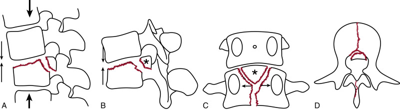
The three-column theory of Denis ( Fig. 7-5 ) proposes that the spine consists of anterior, middle, and posterior columns.
- •
Anterior column: anterior longitudinal ligament, anterior annulus fibrosus, anterior part of the vertebral body
- •
Middle column: posterior longitudinal ligament, posterior annulus fibrosus, posterior part of the vertebral body
- •
Posterior column: neural arch and supporting soft tissue structures
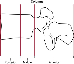
The middle column acts as a hinge between the anterior and posterior columns. The middle column binds the anterior to the posterior column and serves as the fulcrum of motion between these two columns ( Fig. 7-6 A ). If the middle column is intact, the injury is generally considered stable. If the middle column is disrupted, the injury is generally considered unstable.
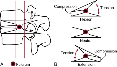
Flexion of the spine produces tension (stretching) forces in the posterior column posterior to the fulcrum and compression forces in the anterior column anterior to the fulcrum ( Fig. 7-6 B ). The opposite occurs in spinal extension; compression forces occur in the posterior column, and tension forces are created within the anterior column ( Fig. 7-6 B ).
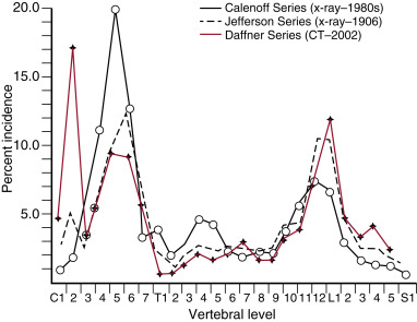
Distribution of fractures
The incidence of fractures in each vertebral segment is variable ( Fig. 7-7 ). Before the advent of CT the incidence of fractures of the upper cervical spine were thought to be relatively low. CT has now shown three peak incidences of spinal fractures: the first in the upper cervical spine (C2), the second in the lower cervical spine (C5 and C6), and the third at the thoracolumbar junction (T10 to L4). In terms of the thoracolumbar spine, it becomes obvious from the incidence curve that imaging of the traumatized lumbar spine must include the lower thoracic spine to avoid oversights of fractures.
Forces of spinal injury
The forces of spinal injury are multiple and therefore complex. The forces are flexion, extension, distraction, compression, shearing, and rotation ( Fig. 7-8 ). The combination of flexion, compression, rotation, and shearing is particularly common. In most injuries one force is dominant, and each force is associated with a relatively specific pattern of injury. In general, compressive forces create fractures, whereas rotational and shearing forces disrupt ligaments, resulting in dislocations.
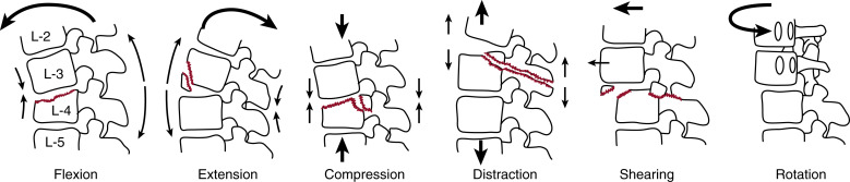
Flexion is the most common force operative in spinal injury. The spine is arched anteriorly, pivoting about the fulcrum of the middle column, which results in compression in the vertebral body and tension within the neural arch posterior to the fulcrum.
Extension forces do the opposite, resulting in tension anteriorly and compression posterior to the middle column.
Compression is due to an axial load across the entire vertebra involving all three columns as in burst fractures.
Distraction forces are the opposite of compression, forces pulling the vertebra in opposite directions in the axial plane, superiorly and inferiorly, as in chance fractures. In such fractures the fulcrum of the forces is displaced anterior to the spine, classically to the seat belt in restrained automobile occupants or occasionally to the handlebars in motorcyclists.
Rotational and shearing forces disrupt ligaments, resulting in dislocations and fracture dislocations.
 3
3
Common forms of fracture and fracture-dislocations in adults
Fracture
Vertebral body
Anterior wedged compression
Burst
Chance (seat-belt)
Flexion-distraction
Extension
Vertebral appendage
Transverse process
Spinous process
Fracture-dislocation
Shearing
Flexion-distraction
What to look for
Check the height and configuration of all vertebral bodies. Once anterior wedging of a vertebral body is identified, determine the precise nature of the fracture: simple compression, burst, or flexion-distraction as described below. Multiple contiguous fractures of vertebrae are common. Examine adjacent vertebrae for evidence of more subtle fractures.
Look closely for evidence of malalignment, a certain sign of fracture-dislocation.
Fracture-dislocations of the upper thoracic spine can be difficult to identify on plain films because of the overlying mediastinal structures and mediastinal hematomas associated with vascular injuries as well as spinal injuries. Any degree of vertebral offset or malalignment is suspect and warrants a CT examination of the spine to confirm or exclude the presence of a significant injury.
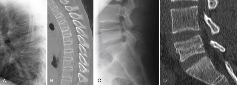
Simple (anterior wedged) compression fractures
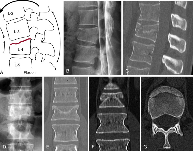
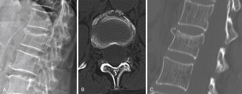
Anterior wedged compression fractures are the result of anterior flexion forces that compress the superior endplate of the vertebrae and reduce the anterior height of the vertebral body ( Fig. 7-9 A, B, C ). On the AP view ( Fig. 7-9 D ) the superior endplate is distorted, poorly defined, or obviously fractured. Compare with adjacent vertebrae. There is often an irregular bulge or fracture fragment at the anterior superior margin of the vertebral body ( Fig. 7-9 A, B, C ). Less commonly the inferior endplate is involved. In either circumstance the posterior wall of the vertebral body remains intact, and the posterior height of the vertebra is maintained. The posterior elements and middle column remain intact. Look for horizontal sclerotic bands indicating areas of trabecular impaction in subtle cases ( Fig. 7-9 C ). Impactions are nicely shown on coronal images ( Fig. 7-9 E, F ). The fracture fragments from the superior endplate are displaced centripetally ( Fig. 7-9 G ). Surprisingly a paraspinous hematoma is not always visible.
The fracture of the anterior superior corner of the vertebral body in anterior wedged compression fractures may be quite prominent in some cases and quite inconspicuous in others. An obvious fracture of the anterior superior corner is shown in an osteoporotic 70-year-old woman ( Fig.7-10 A, B, C ).
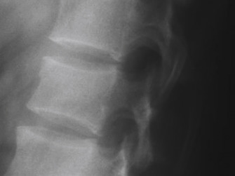
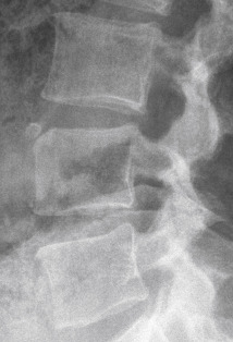
The lateral radiograph of a different patient shows a subtle, small anterior cortical buckle with minimal anterior wedging of the vertebral body ( Fig. 7-11 ).
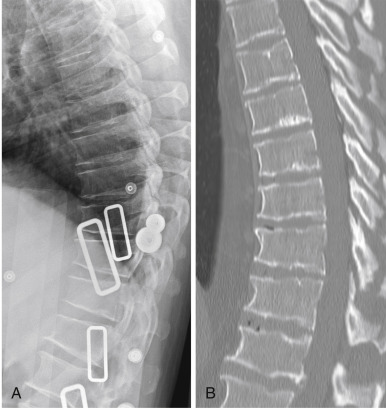
This patient has a T11 anterior superior corner fracture ( Fig. 7-12 A ). Coronal images ( Fig. 7-12 B ) can be extremely helpful in identifying corner fractures along the left or right margin of the vertebral body. Note the surrounding paravertebral hematoma (arrows) ( Fig. 7-12 B, C ).
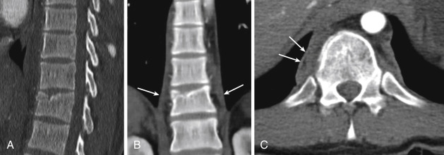
Compression forces may not be evenly applied across the width of the vertebral body. One side is likely to be more affected than the other evidenced by right or left lateral wedging of the vertebral body as seen in the coronal image ( Fig. 7-12 B ).
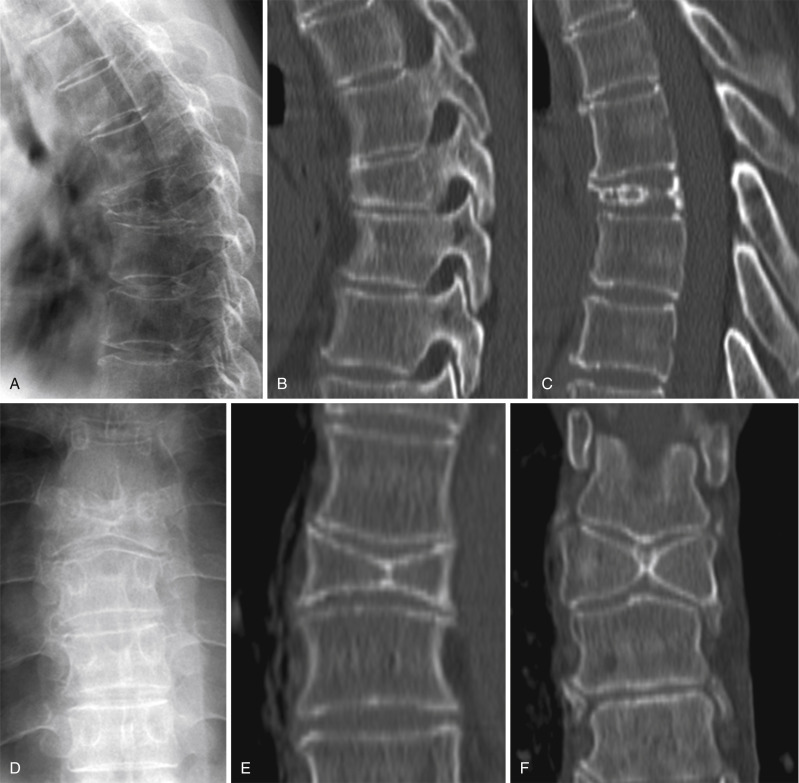
Concurrent compression fractures of two or more contiguous vertebrae may occur. Having found a compression fracture, take a good look at adjacent vertebrae for evidence of additional fractures. This 43-year-old man sustained simultaneous compression fractures of the thoracic spine ( Fig. 7-13 A ). The left parasagittal CT image shows slight anterior wedging and irregularity of the anterior superior corners of two contiguous vertebrae, T10 and T11; these are somewhat more apparent in the mid-sagittal image ( Fig. 7-13 B ) and clearly shown on the left parasagittal ( Fig. 7-13 C ) and coronal ( Fig. 7-13 D ) images. Note that the left sides of the T10 and T11 vertebral bodies are more affected than the right, indicating that the fracture was the result of left lateral compression.
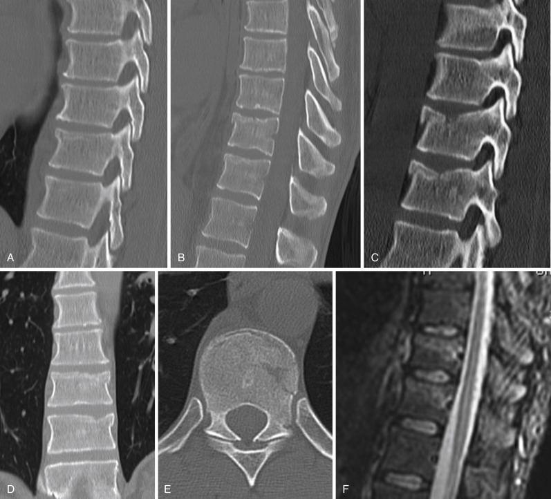
Axial image of the superior surface of T10 demonstrates comminution of the anterior and left lateral surface of the endplate ( Fig. 7-13 E ). Mid-sagittal STIR image shows high signal edema of the superior portion of the T10 and T11 vertebral bodies in keeping with acute vertebral body fractures ( Fig. 7-13 F ).
Simultaneous compression fractures of several contiguous thoracic vertebrae may occur as shown in this 24-year-old man with a history of grand mal seizures. The lateral radiograph of the thoracic spine shows irregularity and wedging of several contiguous vertebrae ( Fig. 7-14 A ), but the fractures are much better seen on coronal CT ( Fig. 7-14 B ). Compression fractures of the vertebral bodies of T2 through T7 are clearly depicted.
Lateral spot view of the lumbosacral junction in this same patient shows a reduction of the height of the L5 vertebral body without wedging or an obvious fracture ( Fig. 7-14 C ). Sagittal CT image discloses an impacted compression fracture of the mid-portion of the L5 vertebral body sparing the endplates. This type of fracture is due to axial compression without a significant flexion component and has been referred to as a “top hat” fracture. It is uncommon.
Pitfalls: limbus vertebra
The most common pitfall in the lumbar spine is a limbus vertebra, a small triangular bone found at the anterior superior margin of a lumbar vertebral body ( Fig. 7-15 ). There is a well-corticated defect in the anterior superior corner of the vertebral body. The opposing margins of both the triangular bone and the underlying corner of the vertebral body are well-corticated. The vertebral body is otherwise of normal configuration without anterior wedging. The limbus bears a superficial resemblance to a bony fragment found in a similar location of an acute anterior wedge-shaped compression fracture. However, in an acute compression fracture, neither the small fragment nor the opposing margin of the vertebral body are corticated, and there is anterior wedging of the affected vertebral body.
Scheuermann’s disease
Scheuermann’s disease is a potential pitfall in the mid and lower thoracic spine. The disease begins in adolescence as an apophysitis affecting the vertebral body apophyses of the mid and lower thoracic spine. Schmorl’s nodes are formed, which create superior and inferior endplate deformities at multiple levels. Findings in a 38-year-old man are shown. The endplates of the affected vertebrae are irregular, and the vertebral bodies are wedge-shaped ( Fig. 7-16 A, B ). This can ultimately result in a kyphotic deformity of the lower thoracic spine.
Butterfly vertebra
Butterfly vertebra is a vertebral anomaly that results from a failure of fusion of the lateral halves of the vertebral body because of persistent notochordal tissue between them. The involved vertebral body is widened, and the vertebral bodies above and below adapt to the altered shape of the butterfly vertebra.
A butterfly vertebra is usually wedge-shaped in its lateral profile, potentially causing it to be mistaken for an acute compression fracture as shown in this 59-year-old woman ( Fig. 7-17 A ).
Sagittal CT image to the right of midline shows anterior wedging of the vertebral body ( Fig. 7-17 B ). A midline sagittal image shows irregular curvilinear ossification and reduced height between adjacent vertebrae ( Fig. 7-17 C ). The irregular ossification is in the persistent notochordal remnant.
On the AP radiograph the affected vertebra is widened and butterfly-shaped as its name implies ( Fig. 7-17 D ). Coronal CT anteriorly shows bony fusion between the two lateral halves ( Fig. 7-17 E ). Coronal CT in the posterior half of the vertebra shows a separation between the two lateral halves and widened vertebra as compared to adjacent vertebrae ( Fig. 7-17 F ).
Checklists for analysis of anterior wedging of vertebral body includes (in free verse):
- •
Is the posterior height of affected vertebral body intact?
- •
Are posterior elements intact?
- •
Is vertebral alignment maintained?
- •
If so, this is a simple anterior wedged compression fracture.
- •
- •
Is the posterior cortical surface of the vertebra intact?
- •
If not, is there a bony fragment from the posterior superior portion of the vertebral body displaced into spinal canal?
- •
If so, this is a burst fracture.
- •
- •
Is there a horizontal fracture in the posterior aspect of the vertebral body?
- •
Is the upper fragment displaced superiorly?
- •
Is there a horizontal fracture of the posterior elements or a distraction of the posterior elements of adjacent vertebra? If so, this is a flexion-distraction fracture.
- •
- •
Is there malalignment of adjacent vertebra?
- •
If so, this is a fracture-dislocation.
- •
Burst fractures
Burst fractures are the result of compression forces across all three spinal columns ( Fig. 7-18 A ). These produce an anterior wedged deformity of the vertebral body with a characteristic triangular fragment from the posterior superior margin of the vertebral body retropulsed into the spinal canal ( Fig. 7-18 A, B ). On coronal CT there is usually a vertical fracture in the sagittal plane of the vertebral body ( Fig. 7-18 C ). Axial CT shows a sagittal fracture in the midline of the lower aspect of the vertebral body, the retropulsed fragment, and a sagittal fracture of the lamina commonly located at the junction of the lamina with the spinous process ( Fig. 7-18 D ).
Burst fractures present with anterior wedging of the L1 vertebral body as shown on the lateral radiograph ( Fig. 7-19 A ). The classic finding is retropulsion of a fragment from the posterior superior surface of the vertebral body into the spinal canal as shown in this case ( Fig. 7-19 A ). Note the widened interspinous distance (arrows) of L1 on the AP view; compare with T12 and L2 ( Fig. 7-19 B, C ). This finding is present in the majority of cases. These radiographic findings are pathognomonic of a burst fracture.