The aorta, the largest artery in the body, pumps up to 200 million L of blood in an average lifetime. Thoracic aortic diseases range from chronic to acute and have a wide variation in symptoms. Consequently, pathologic features of the aorta may be detected incidentally (as in an aneurysm incidentally detected on imaging) or as a result of severe chest pain (as in acute aortic dissection). The increase in the reported prevalence of aortic disease in developed countries is most likely the result of improved clinical awareness and increased life expectancy.
Noninvasive imaging is central to the diagnosis and management of disorders of the thoracic aorta. Initial examination of the aorta should include the entire aortoiliac system. Aortic diseases such as aneurysm or dissection frequently often extend along large portions of the aorta or may be multifocal.
Radiography
Chest radiographs have a limited role in the assessment of the thoracic aorta, given its low inherent contrast. The main utility of radiography in aortic diseases is in the emergency setting in which an anteroposterior (AP) chest radiograph acts as a screening tool to exclude actionable traumatic aortic injury. The negative predictive value of a normal chest radiograph is 98% in the setting of blunt trauma. Imaging abnormalities are based on the assumption that aortic injuries result in mediastinal hematomas. Common findings include superior mediastinal widening, right paratracheal stripe thickening, abnormal aortic morphology, obliteration of the aorto-pulmonary window, rightward deviation of mediastinal structures or thickening of the left paraspinal interface (given that the descending aorta is a left-sided structure), left hemothorax, and inferior displacement of the left mainstem bronchus ( Fig. 44-1 ). Intimal injuries, however, cannot be detected without the use of intravenous contrast.

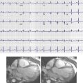
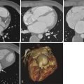
Severe calcification of the aorta, its branches, and aortic valve leaflets is readily detected on radiography, although mild calcification may be subtle or undetectable. Aortic valve calcification is better demonstrated on lateral radiographs and when present, it is highly suggestive of significant aortic stenosis ( Fig. 44-2 ). The aortic valve is located above an imaginary line drawn along the long axis of the heart on the lateral view. One often sees associated dilation of the ascending aorta from a poststenotic jet phenomenon, which manifests as broad convexity just superior to the right heart border. Aortic dilation and congenital anomalies may also be detected using posteroanterior and lateral chest radiographs; however, detailed imaging assessment of the thoracic aorta requires further evaluation with cross-sectional imaging. Rarely, displacement of the calcified intimal surface can be detected on radiography, and this finding is essentially diagnostic of aortic dissection ( Fig. 44-3 ).


Computed Tomography Imaging Protocol
In the 1990s, single detector spiral computed tomography (CT) was introduced into clinical practice. This technique allowed for excellent visualization of vessels in multiple planes. However, CT was still limited by long breath holds, motion artifacts from slow gantry rotation time, and limited z-plane coverage. Later in the 1990s, multidetector row CT (MDCT) was introduced to wide acclaim. MDCT resulted in improved z-axis resolution, rapid gantry rotation, increased coverage in the z-axis, and increased table speed. Modern 64- to 320-row MDCT can evaluate the entire aorta and its branches in a single short acquisition. Unlike with catheter angiography, the walls of vessels are also well assessed with MDCT. Catheter angiography is essentially a study of the vessel lumen (luminography). Given the nearly isotropic acquisition of current MDCT, two-dimensional and three-dimensional reconstructions can be made retrospectively in any orientation.
Noncontrast Computed Tomography
Inclusion of a noncontrast CT scan is mandatory in aortic imaging because intramural hematomas (IMHs) are more evident without intravascular contrast ( Fig. 44-4 ). In addition, calcified atherosclerotic plaque is more easily detected. A noncontrast phase may also be helpful in patients with calcified lymph nodes or metallic surgical material or felt pledgets or rings, which can simulate vascular disease during the arterial phase. Finally, in the rare case of a vascular mass, noncontrast acquisition is necessary to assess the degree of enhancement within the lesion confidently. Internal enhancement is more suggestive of neoplasm, whereas thrombus or iatrogenic material typically does not demonstrate significant enhancement. The radiation dose can be reduced during this phase by increasing collimation, decreasing peak kilovoltage, or increasing the noise index.

Computed Tomography Angiography
Thoracic aortic CT angiography (CTA) is usually performed with a pitch of 1 to 1.5, a collimation of 0.5 to 1.0 mm, and reconstruction thickness of 1.0 to 1.5 mm with spacing of 0.75 to 1 mm. The tube potential is usually between 120 and 140 kVp. Lower tube potential (80 to 100 kVp) may be used in pediatric patients or in those with a lower body mass index. Automated tube current modulation should be used when available; tube current is automatically decreased while scanning areas with lower attenuation (the midchest, where much of the anatomy consists of air-filled lungs) and is increased for areas with higher attenuation (upper chest and shoulders, upper abdomen). A desired noise index is set, defined as the standard deviation of Hounsfield units in the center of an image using soft tissue kernel reconstruction.
A threshold-based bolus tracking strategy is typically used with a region of interest in the ascending aorta. Intravenous contrast material is injected at rates of 3 to 5 mL/second. The overall contrast volume can be calculated as injection rate (in milliliters per second) multiplied by [scan duration in seconds + 5 to 10 seconds]. The contrast material must be injected for an additional 5 to 10 seconds to compensate for the time it takes for gantry movement from the position of the bolus tracking in the ascending aorta and the start position of the CTA scan in the neck. Alternatively, a fixed amount of contrast—based on an injection period of 20 to 35 seconds—can be used and usually results in similar image quality. Reconstructing a small field of view in x-y dimension is advantageous for optimizing spatial resolution of the aorta and its branches. However, a full field of view is mandatory to detect potentially significant incidental findings or secondary findings within the end organs. Initial evaluation of the thoracic aorta should include the abdominal aorta and iliac arteries because aortic disease may be multifocal or may extend throughout the thoracic and abdominal aorta, unless the status of the abdominal and pelvic vessels is known.
Delayed Scan
A delayed scan 2 minutes after injection is useful to assess for late filling of a false lumen in dissections, slow endoleaks in endovascular aneurysm repair, or contrast extravasation from aortic rupture.
Postprocessing
Multiplanar maximum intensity projections (MIPs) in the sagittal plane, sagittal oblique plane (candy cane view), coronal plane, aortic short axis, and aortic root long axis are routinely acquired. Three-dimensional volume rendered images are often acquired and can be helpful to identify major disease or for surgical planning. However, axial reconstruction and interactive multiplanar reformations are usually clinically more useful.
Magnetic Resonance Imaging Protocol
As opposed to imaging of the thoracic aorta with CT, magnetic resonance angiography (MRA) of the thoracic aorta most often requires multiple magnetic resonance imaging (MRI) methods to evaluate the aorta adequately. The most utilitarian tool in MRI of the aorta is contrast-enhanced (CE) MRA. Images similar to conventional invasive angiography are reconstructed from a single three-dimensional acquisition or from a dynamic MRA acquisition (several consecutive breath-held acquisitions). Black-blood imaging (traditionally with spin echo imaging, which has been supplanted with more advanced techniques) is used primarily to evaluate the walls of the aorta, given the high contrast between signal in the fixed mediastinal structures and flowing blood. Gradient echo sequences allow for qualitative functional and morphologic evaluation of the aortic valve. In addition, quantitative data on vascular flow can also be acquired using velocity encoded cine MRI.
Contrast-Enhanced Magnetic Resonance Angiography
With the advent of rapid gradient systems, three-dimensional CE MRA is the most often used means to evaluate the aorta. Time of flight (TOF) imaging may also be used as a concomitant sequence; however, given its limitations in areas of slow or turbulent flow, TOF imaging is rarely used in isolation unless the patient has a contraindication to gadolinium contrast administration. CE MRA relies on the T1 shortening effect of gadolinium contrast and is less prone to imaging artifact. The exact protocol for CE MRA differs among institutions and MRI scanners. As a general rule, however, contrast material is injected through an antecubital vein with a power injector at a rate of approximately 2 mL/second (0.2 mmol/kg of body weight). The injection rate should be adjusted to avoid unnecessary injection of contrast material beyond the scan time. Bolus timing is mandatory, given the short intravascular phase of maximal contrast enhancement. Imaging before the peak plateau of contrast enhancement may result in ringing artifact, whereas delayed imaging leads to venous contamination, which complicates differentiation of arterial and venous structures. Real-time imaging or a test bolus technique can be employed to determine the optimal time point to scan the patient after injection of the contrast material. A T1-weighted gradient echo sequence is acquired using short repetition time (TR; 3 to 5 msec) and echo time (TE; 1 to 2 msec) with a large flip angle (45 degrees). Images are acquired using a single breath hold lasting from 20 to 30 seconds. Supplemental oxygen as well as hyperventilation can aid patients in achieving this breath hold, which can be challenging in patients with cardiorespiratory disease. Electrocardiogram (ECG) gating is not necessary to perform this sequence.
A precontrast mask image before the CE acquisition is often helpful for background suppression. The precontrast sequence method is similar to that of the CE sequence. The precontrast mask images are then subtracted from the CE images before MIP images are postprocessed from the source data. Most often, the MIP images are reconstructed as projection images that resemble conventional angiographic images. Given the nearly isovolumetric acquisition of the CE MRA sequence, reformation can be created in any plane that is advantageous in vascular imaging, considering the high variation in the course and size of the vasculature in different patients.
Noncontrast Magnetic Resonance Angiography
Although noncontrast MRA has been available for many years, it was initially inferior to CE MRA and therefore was not frequently used. However, the more recently recognized risk of nephrogenic systemic fibrosis and nephrogenic fibrosing dermopathy with administration of gadolinium compounds in renally impaired patients led to renewed focus on noncontrast MRA techniques. Most of the noncontrast MRA use bright-blood imaging techniques that show bright signal in an voxel through which fluid flows.
Gradient Echo Imaging
Also known as bright-blood imaging, gradient recalled echo imaging results in high signal in flowing blood. Combined with retrospective or prospective gating, cine sequences at specific points in the anatomy can be acquired that provide both dynamic and functional data, albeit at the expense of less detail within the walls of the vessels. High signal in flowing blood is achieved with a very short TR (4 msec) and a low flip angle (20 to 30 degrees). TE is also short (1 to 2 msec). Signal in vessels is reduced with slow flow; nonlaminar turbulent flow results in spin dephasing and concomitant low signal that often suggest the presence of an underlying structural abnormality. Filling defects within the aorta, as well as aortic valvular dysfunction, are readily identifiable using this method.
Black-Blood Imaging
Black-blood imaging of the thoracic aorta is essential in the assessment of the aortic wall. The high contrast between flowing blood and the aorta is valuable in the evaluation of acute aortic syndrome, vasculitis, and atherosclerosis. Traditionally, black-blood imaging was obtained with a spin echo technique, using a pair of slice-selective radiofrequency pulses at 90 and 180 degrees. Protons in flowing blood resulted in a signal void in vessels not in the plane of acquisition. More advanced techniques, such as fast spin echo and breath-hold inversion recovery, have largely supplanted simple spin echo imaging in thoracic aortic evaluation, given their superior resolution and decreased susceptibility to motion artifact.
Normal Anatomy
The thoracic aorta extends from the aortic annulus to the diaphragm. The thoracic aorta can be divided into three major parts: the ascending aorta, the aortic arch, and the descending thoracic aorta ( Fig. 44-5 ). The aortic root and the tubular ascending aorta comprise the ascending aorta. The aortic root lies between the aortic annulus and the sinotubular junction. The sinuses of Valsalva are found in the aortic root. The tubular ascending aorta consists of the portion of the aorta between the sinotubular junction and the brachiocephalic artery. The first 3 cm of the proximal ascending aorta is within the confines of the pericardium. The ascending aorta is devoid of branches except for the coronary arteries. The aortic arch is between the brachiocephalic trunk and the origin of the left subclavian artery. The isthmus is a small segment of the aorta extending from the left subclavian artery to the ligamentum arteriosum. Three branches most commonly arise from the aortic arch: the brachiocephalic artery (innominate artery), the left common carotid artery, and the left subclavian artery. The descending thoracic aorta extends from the isthmus to the diaphragm. In contradistinction to the ascending aorta, the descending aorta has multiple branches including the bronchial, intercostal, spinal, superior phrenic arteries and various small mediastinal branches.

Anatomic Variants (Asymptomatic)
In approximately 7% of people, the left vertebral artery arises directly from the aortic arch. This finding is of limited clinical significance in most instances, although knowledge of this normal variant anatomy may be helpful before neuroangiography procedures. The bovine arch is another normal variant in which the left common carotid artery arises directly from the brachiocephalic artery and occurs in up to one fourth of the population (see Fig. 44-5 ). The bovine arch is, in fact, a misnomer for this aortic variant. Cows have a single brachiocephalic trunk that splits into the subclavian arteries and a bicarotid trunk. A common arch variant is the ductus diverticulum, which is a focal convexity along the inner aspect of the aortic isthmus that represents a remnant of the ductus arteriosus. Uncommonly, the aorta may extend above the level of the clavicles into the lower aspect of the neck ( Fig. 44-6 ). Known as a cervical aortic arch, this anomaly is usually an isolated finding. However, cervical aortic arches may occur in patients with cardiac defects (most commonly ventricular septal defects or conotruncal abnormalities). In addition, cervical aortic arches may result in a vascular ring when the cervical arch and the descending thoracic aorta are contralateral (most often the case), thus leading to chronic tracheoesophageal compression and asthma-like symptoms.

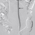
In approximately 0.5% of people, the right subclavian artery may arise anomalously from the proximal aspect of the descending thoracic aorta and almost always passes into the right hemithorax behind the esophagus ( Fig. 44-7 ). This anomaly does not typically result in a vascular ring and is therefore often asymptomatic or minimally symptomatic. However, dysphagia may result from compression of posterior aspect of the esophagus (dysphagia lusoria).

Pseudocoarctation is a normal variant of the aortic arch and proximal descending artery that occurs when the third to seventh embryonic dorsal segments fail to fuse appropriately; the resultant high proximal arch leads to kinking of the redundant aorta where it is tethered to the pulmonary artery by the ligamentum arteriosum ( Fig. 44-8 ).

Anatomic Variants (Symptomatic)
The right aortic arch, the most common asymptomatic arch anomaly, is thought to result from persistence of the entire right dorsal arch and involution of a segment of the left arch. Chest radiography shows abnormal leftward deviation of the trachea. In normal circumstances, the trachea is pushed slightly toward the right by a left-sided aortic arch. Cross-sectional imaging (CT or MRI) is usually diagnostic. The two main types are right aortic arch with aberrant left subclavian artery and right aortic arch with mirror image branching. In cases of right aortic arch with an aberrant left subclavian artery, the aberrant left subclavian almost always passes behind the esophagus and is often seen on lateral chest radiograph or esophagogram ( Fig. 44-9 ). A ring usually results from the left-sided ligamentum arteriosum. Patients commonly present with tracheal symptoms resembling asthma. In mirror image branching, the normal branching pattern of the aorta is completely reversed, and no vascular ring is present. However, this anomaly is highly associated with congenital heart disease (most commonly tetralogy of Fallot).

A double aortic arch results from persistence of both fourth aortic arches during development. This anomaly is the most common symptomatic vascular ring; patients usually present in the early months of life with inspiratory stridor that is worse with feeding. On radiography, the trachea is abnormally at midline or deviated away from the dominant arch. Cross-sectional imaging is again most often diagnostic ( Fig. 44-10 ). More commonly, the right aortic arch is larger and more superiorly located than the left aortic arch. The carotid and subclavian arteries arise from the ipsilateral aortic arch and result in the four artery sign: symmetric branching of the carotid and subclavian arteries in the superior thorax. In a minority of cases, a portion of the double aortic arch may be atretic, although the ring remains intact because of a persistent fibrous band of tissue in the atretic portion of the aorta.

Interrupted aorta results from regression of both fourth arches during development such that the ascending aorta and descending aorta are no longer in continuity. The descending aorta is perfused by the patent ductus arteriosum or collateral arteries ( Fig. 44-11 ). A strong association exists between interrupted aortic arch and congenital heart defects (most commonly ventricular septal defects). Other anomalies may also occur (truncus arteriosus, transposition of the great arteries, and aortopulmonary window).