Introduction
Recent years have seen an ever-burgeoning literature based on three-dimensional ultrasonography (3DUS) of the fetus. 3DUS of the fetal heart presented particular challenges, related to the difficulties of imaging a moving object in three dimensions. With improvements in technology and data processing came methods of gating and image correlation that meet these challenges and allow near–real-time 3DUS of the fetal heart. Spatiotemporal image correlation (STIC) technology, introduced in 2003, adds the fourth dimension (time). Today, it is customary to refer collectively to 3D/4DUS of the fetal heart, encompassing the many combinations of acquisition and post-processing modalities and techniques available.
In this chapter, we describe these techniques briefly (with minimal technical information: the interested reader will refer to technical materials supplied by the vendor), beginning with the acquisition modalities and continuing with post-processing modalities; then moving on to their practical application, including traps and pitfalls to avoid; and finally, when and where various methods are most useful in the work of fetal echocardiography.
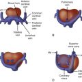
The International Society of Ultrasound in Obstetrics and Gynecology (ISUOG) has published guidelines for the performance of the “basic” and “extended basic” fetal cardiac scan. These guidelines include all the cardiac parameters necessary for complete fetal echocardiography. The sequential segmental approach to fetal cardiology divides the heart into three basic segments, the atria, ventricles, and great arteries. These are interfaced by the atrioventricular valves and the ventriculoarterial junctions. By applying the five planes of fetal echocardiography methodology, which is based on a 2DUS sweep from the fetal upper abdomen to the upper mediastinum, five short-axis planes of the fetal heart are visualized that provide the examiner with all the elements of the heart as described by the sequential segmental approach and include all the parameters cited by the ISUOG guidelines.
Volume Acquisition
3D/4DUS scans are based on a volume block of data made up of numerous voxels (volume display units [volume pixels]). Once acquired and saved, this block of data is available for manipulation and analysis. Some displays are available almost immediately and can be viewed with the patient still present, whereas others require considerable time and effort and are usually achieved after the patient is dismissed.
Spatiotemporal Image Correlation
STIC acquisition is the mainstay of 3D/4DUS of the fetal heart. The modality has been extensively described and numerous publications have been based on its use. STIC is an indirect, offline, motion-gated scanning mode. The operator scans the region of interest in a sweep (in the fetal heart, this would be a sweep beginning just caudal to the four-chamber view and then moving cephalad to the upper mediastinum). The array in the transducer makes this automated volume acquisition possible. The array performs a single slow sweep of 7.5 to approximately 30 seconds, for a sweep angle of 20 to 40 degrees (depending on the size of the fetus) and a frame rate of up to 150 frames/sec. An acquisition of 10 seconds and 25 degrees, therefore, would include approximately 1500 sequential B-mode images. Following this acquisition sweep, the STIC program uses mathematical algorithms to process the volume data. It identifies the systolic peaks that will be used to calculate the fetal heart rate. These peaks then act as triggers for correlation of the spatial and temporal position of each B-mode image. STIC acquisition is designed to mimic the traditional abdomen-to-mediastinum sweep of 2DUS, and a well-executed and acquired STIC volume will contain all five short-axis planes of fetal echocardiography and all the data necessary for fetal cardiac examination as set out by the ISUOG guidelines . In practice, owing to fetal breathing movements and other sources of interference, two or more acquisitions are usually required for a complete heart scan.
B-Flow
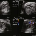
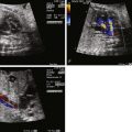
B-Flow is an ultrasound technology that images blood flowing in its vessels, without relying on Doppler shift. B-Flow is made possible by the digital encoding of one ultrasound beam into two sub-beams: one beam provides structural B-mode display and the other contains B-mode flow display of blood flow and part of the lumen. This flow display is enhanced to make up for the weak signal from blood cell reflectors. B-Flow uses faster frame rates than Doppler flow mapping and provides better spatial resolution. Because it is not based on Doppler shift, B-flow is angle-independent and avoids image drop-out at orthogonal scanning angles. The greater sensitivity of B-flow makes it an excellent tool for the measurement of blood vessel dimensions. When B-flow is used in tandem with STIC to image the fetal heart, the threshold is set high to eliminate the surrounding tissue and show the enhanced, high-intensity B-flow signal. The result is a 3D moving impression of blood flowing in the heart and great vessels that we have found remarkably sensitive for imaging the normal heart as well as great vessels anomalies such as transposition of the great arteries and others ( Figure 4-1 ).

Doppler Applications
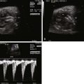
Doppler applications, color Doppler, power Doppler, and high-definition power flow Doppler (HDPD) have been used extensively in combination with 3D/4DUS. Static 3DUS acquisition is preferable for use with three-dimensional power Doppler (3DPD), and STIC acquisition can be combined with color Doppler or with HDPD. HDPD is a bidirectional color Doppler mode that operates at lower velocity than either standard color Doppler or power Doppler. But whereas power Doppler is unidirectional, HDPD has the added advantage of directionality. Its greater sensitivity provides a cleaner image with less blooming of color beyond vessel walls than in regular or power Doppler ( Figure 4-2 ).

Post-processing Applications
Once the volume block has been acquired and stored to the ultrasound machine, it is available for extensive manipulation and analysis in post-processing. Each application allows manipulation of different aspects of the volume data; the applications can also be combined sequentially to a given saved volume to extract biometric and functional parameters.
Multiplanar Reconstruction
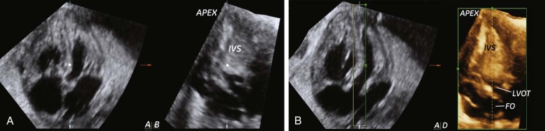
In order to analyze the acquired volume block effectively, it is necessary to “slice” it into two-dimensional planes. The multiplanar reconstruction (MPR) application displays three orthogonal planes from the volume and allows the operator to navigate within the volume along three axes. The point of intersection of all three planes is anchored at a navigation dot that assists the operator in orientation within the volume ( Figure 4-3A ). In the case of stored STIC volumes, which contain temporal information, it is also possible to scroll forward and backward in time and to review the beating heart in a virtual cine loop of the heart cycle.
Three-Dimensional Rendering
3D rendering is familiar from surface-rendered images of the fetal face, body, and limbs. When applied to the fetal heart, 3D rendering is applied to the MPR display in post-processing. Once the desired plane is achieved in MPR display, a bounding box is placed around the region of interest and the rendered image is shown in the fourth frame of the display (see Figure 4-3B ). The rendered image has the advantage of including depth, which reflects the thickness of the slice through the volume (i.e., the width of the bounding box). For example, when applied to imaging the interventricular septum, the characteristic trabeculations of the right ventricle are clearly seen. If the original acquisition was combined with STIC and/or color Doppler, these parameters are available in the rendered image.
Tomographic Ultrasound Imaging
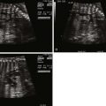
Whereas MPR displays three orthogonal planes of a volume, and 3D rendering adds depth to one selected plane from the MPR display, tomographic ultrasound imaging (TUI) allows for the display of a matrix of sequential parallel planes. This capability shows the reference plane at the center of the matrix, with its adjacent slices arranged in order around it. The number of slices displayed and the distance between them are set by the operator. This capability has been applied to fetal echocardiography in normal and anomalous hearts and allows the display of some or all of the five planes of fetal echocardiography simultaneously ( Figure 4-4 ). As is the case with MPR and rendering, when STIC acquisition is used, temporal information is available in the TUI display and, if combined with Doppler mapping, color will be available.

Virtual Organ Computer-Aided Analysis
Virtual organ computer-aided analysis (VOCAL) is used in post-processing to measure the volume of a target organ. The application performs a rotational measurement of volume as the dataset is rotated 180 degrees around a fixed central axis through a preset number of rotation steps based on the angle of rotation (i.e., 6 steps of rotation 30 degrees apart, for example, in the case of a regular-shaped object, or 12 steps 15 degrees apart, where necessary). Thus, the contours are traced manually or automatically at each plane in sequence, and the system reconstructs a contour model and provides a volume measurement.
Inversion Mode
Inversion mode (IM), as its name implies, is a post-processing application that inverts the color of acquired voxels so that echogenic (solid) areas are displayed in black, and fluid-filled areas are displayed in gray. This modality has been applied to the fetal heart to create “digital casts” of the fetal heart ventricles and great vessels ; however, B-flow is more effective for this purpose.
The Methodology of 3D/4D Fetal Echocardiography
As stated previously, STIC is the mainstay of 3D/4DUS of the fetal heart. The optimal acquisition technique has been described at length elsewhere. Briefly, the fetus should be in a quiet state without breathing movements and in supine lie. The operator identifies the four-chamber view, initiates the STIC application, and sweeps the fetal body from the upper abdomen to the upper mediastinum. Ideally, this acquired volume will contain all the images necessary for complete examination of the fetal heart. In practice, part of the volume may be degraded by maternal or fetal motion or breathing, and another volume acquisition will be necessary. Because the first processing stage performed by the ultrasound machine requires only seconds, the volume can be reviewed briefly with the patient present and repeated, without untoward delay. We find that most normal scans require two volumes, and extracting the acceptable portions of each will provide all the necessary planes. In cases of suspected or known fetal anomalies, of course, the approach will be focused on the affected parts to optimize visualization still further, and multiple volumes may be necessary.
Planes and Virtual Planes in Fetal Echocardiography
2DUS can effectively image the five planes of fetal echocardiography as well as countless others. However, many planes are not readily accessible in 2DUS. One of the strengths of 3D/4DUS is the possibility to image “virtual planes” that are acquired in the volume block and, through post-processing manipulation, made available for assessment. For example, the interventricular septum can be evaluated to confirm or exclude the presence of ventricular septal defect (VSD). At the beginning of the evaluation, the operator scrolls through the volume to obtain the four-chamber view in the A-plane of the MPR display. By placing the navigation dot on the interventricular septum, the orthogonal B-plane will show the septum en face, a plane not generally accessible in 2DUS. By applying 3D rendering and placing the bounding box tightly around the septum, the D-frame on the lower right of the display will show the en face view of the ventricular septum and the foramen ovale with the advantage of the depth the bounding box provides (see Figure 4-3 ). In either case, temporal information in the STIC volume allows the resulting plane to run through the cardiac cycle: this allows for evaluation of the action of the foramen ovale during the heart cycle or of blood flow across the VSD.
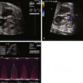
The same algorithm may be applied to visualizing the coronal atrioventricular valve (CAV) plane. Beginning from the four-chamber view, with the navigation dot placed on the crux of the heart, the coronal C-plane will show the CAV plane of the heart. With the bounding box placed tightly around the level of the atrioventricular valves in rendering mode, the D-frame will display the CAV plane. This plane facilitates evaluation of the patency of the atrioventricular and arterial valves ( Figure 4-5 ).

Applying 3D/4DUS to Fetal Echocardiography
Each 3D/4DUS modality brings different advantages to fetal echocardiography. The following examples illustrate the application of various modalities to the diagnosis of fetal cardiac anomalies.
Multiplanar Reconstruction and Tomographic Ultrasound Imaging
MPR is the first-line approach to analysis of an acquired volume block and allows the operator to view three orthogonal planes simultaneously. With the help of the navigation dot, the operator can compare the same point in space in three planes positioned at right angles to each other. Figure 4-6 shows a case of suspicious finding in the A-plane, which proved to be an anomalous blood vessel when viewed in the orthogonal B-plane. This was identified as the characteristic vertical vein of total anomalous pulmonary venous connection, leading ultimately to the diagnosis.