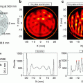
Fig. 4.1
Example of a report page of a rest/stress myocardial perfusion study using 99mTc-sestamibi SPECT. The report shows the images reoriented according to the cardiac axis (short cardiac axis on the upper two rows, vertical long axis on the lower left rows, horizontal long axis on the lower right rows). For each view, the stress image is shown on top and the rest image below. The white arrow indicates an area of reduced perfusion in the apex in the stress image
Besides cardiology, SPECT is also frequently used in oncology and neurology, as well as imaging of infection and inflammation [7]. Small-animal SPECT systems are also used extensively for preclinical research in these same areas [8, 9].
4.2.2 Principles of the Conventional SPECT Data Acquisition
Although some recent scanners propose innovative architectures and different acquisition procedures, we will describe here the acquisition on SPECT systems based on a rotating gamma camera, which are still the most common ones and serve as a starting point to understand different SPECT architectures.
The conventional SPECT acquisition with a rotating gamma camera is done using the step-and-shoot mode: a projection is acquired for some time (shoot), the camera rotates (step), the next projection is acquired, the camera rotates again, etc., acquiring projections at a given number of evenly spaced angular locations (Fig. 4.2).
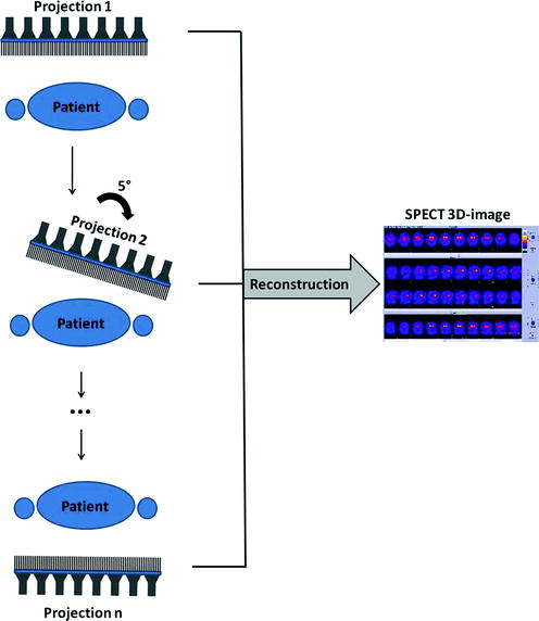

Fig. 4.2
Principle of the conventional SPECT data acquisition with a rotating gamma camera. In this example, projections are acquired with an angular step of 5° over 180°. Using all projections, a three-dimensional SPECT image is reconstructed
An important acquisition parameter is the total angle coverage. In principle, projections covering only 180° of rotation are required for reconstruction: opposing views should, when using an ideal projection, contain the same information and thus be redundant. However, due to the spatial-dependent resolution as well as the attenuation and scatter of the photons within the patient, opposing views are not identical to each other in SPECT. Acquiring a 360° acquisition can thus improve the image quality for some imaging tasks and is occasionally preferred [10]. Additional choices of the acquisition are the rotation angle between projections and the acquisition time for each projection which can be defined alternatively as the number of detected photons for each projection. These choices usually reflect a compromise between the targeted image quality and the total acquisition time and vary according to the sensitivity of the scanner.
As described in the previous chapter, the collimation used in a gamma camera is a critical factor for its performance. The same is valid for SPECT: the collimation reflects the compromise between sensitivity and spatial resolution [11]. Most clinical SPECT systems use gamma cameras with parallel-hole collimation; often, a range of parallel-hole collimators is included, among which the user can choose according to the imaging task and the radioisotope involved (see Chap. 3, Table 3.4).
After acquisition, the image reconstruction algorithm and the parameters chosen for the algorithm play a fundamental role in the resulting SPECT images. This topic will be covered in later chapters of this book.
4.2.3 Static, Gated, Dynamic, and Listmode Acquisitions
By recording and sorting the detected photons in different ways, different acquisition modes are possible:
Static. The basic SPECT acquisition is the static acquisition, where the tracer distribution is assumed to be static during the examination. A single image is generated showing the average tracer distribution over the complete acquisition time.
Gated. In a gated acquisition, the acquired data is sorted into different bins according to the phase at each time-point of a physiological process, typically the cardiac beating or respiration. Subsequently, one image (gate) corresponding to each phase can be reconstructed. For cardiac SPECT, it is common to acquire and reconstruct cardiac-gated images [12, 13]: by recording an ECG simultaneously with the SPECT acquisition and sorting the detected photons in different images according to the cardiac phases, a sequence of images (typically 8–16) from systole to diastole is obtained. The image series can be used to analyze the ventricular function and the myocardial wall motion. It is important to note that the image of each cardiac phase is not acquired during a single beat but as the average over several cardiac cycles. In patients with arrhythmia, irregular beats are usually rejected in order to correctly capture the cardiac beating. For cardiac imaging, it is common to perform an ECG-gated acquisition and then compute a static image as the sum of all gates. In some situations such as lung imaging, respiratory gating is applied [14], which is similar to cardiac gating except that the acquisition is triggered with a respiratory signal rather than with the ECG; the resulting image series ranges then from end-inspiration to end-expiration.
Dynamic. The dynamic acquisition mode provides a temporal sequence of images showing the change of tracer distribution with time [15]. The data is sorted here into temporal bins according to a temporal framing scheme predefined by the user. Due to low sensitivity and subsequently long acquisition time, dynamic acquisitions are uncommon with conventional SPECT systems but might gain importance in the future with newer SPECT systems.
Listmode. The most flexible way to acquire the SPECT data is the so-called listmode acquisition, in which each detected photon is recorded together with the time of detection. In parallel, physiological signals (ECG or respiration) might be recorded. After acquisition, the user decides how to sort the listmode data to arbitrarily generate static, gated, and/or dynamic images, according to the purpose of the examination. Listmode format thus allows preserving the flexibility to post-process the data in different ways. However, in clinical routine, this flexibility is rarely needed, and the acquisition is seldom recorded in listmode format because of the large storage space required.
4.2.4 Improvements in SPECT Technology
Different technologies have been developed to enhance the conventional SPECT acquisition as described in the previous paragraphs. The most relevant advances are presented below, excluding hybrid SPECT/CT imaging which will be detailed in a later section.
Multiheaded cameras. Multiheaded cameras consist in the simultaneous use of several rotating gamma cameras. They increase the fold of sensitivity by the number of heads, allowing a faster SPECT acquisition with preserved image quality. The most common configuration, two-headed SPECT, has two cameras mounted at, for example, 90° or 180°, of each other. Also triple-headed systems with 120° spacing are available. Multiheaded cameras have been available for more than two decades and represent nowadays the majority of the installed SPECT systems.
Continuous and pseudo-continuous acquisition. In the step-and-shoot acquisition, the camera does not acquire data during each rotation step. By using a continuous acquisition mode with a large number of small rotation steps, the counting efficiency can be maximized and a higher angular sampling can be achieved [16]. Therefore, some systems allow continuous acquisition modes or, more frequently, pseudo-continuous modes which perform sequential rotational steps but keep acquiring data during the rotational motion.
Noncircular acquisition. In the conventional SPECT architecture, the spatial resolution and sensitivity decrease with increasing distance between the imaged object and the detectors. In order to minimize the distance between the patient and the detectors, noncircular acquisitions can be used. The gamma camera follows elliptical orbits or tracks and contours the patient’s body, effectively minimizing the distance and improving the spatial resolution [17, 18].
Collimator design. Since the development of the first gamma camera, different collimator designs were investigated, and their potential advantages were recognized [11]. However, parallel-hole collimators have been used in most systems. Recently, clinical systems which use alternative collimator designs such as slit/slats or multi-pinhole collimation have been commercialized. These have been shown particularly useful when the examination focuses on a small region of interest (e.g., cardiac imaging), resulting in higher sensitivity and spatial resolution for this area. In small-animal systems, submillimeter resolution has been demonstrated with multi-pinhole collimation [19–21].
Attenuation correction. A large fraction of photons interact with the patient’s body. As a result of the interaction, the photons do not reach the detectors or change their original directions before being detected, introducing artifacts in the images (see Chap. 3, Fig. 3.6). These artifacts can be minimized by correcting for scatter and attenuation. These corrections require an attenuation map with the radiodensity of each voxel, and two ways have been developed to measure the attenuation map: using a rotating radionuclide source to acquire a transmission scan through the body (as opposed to the emission scan) [22] or using the CT component in hybrid SPECT/CT scanners. However, attenuation correction is challenging in SPECT because the probability of a photon interacting with the patient’s body depends on the depth at which the photon was emitted.
Iterative image reconstruction. Over the past years, there has been a shift from analytical reconstructions, mainly filtered backprojection (FBP), to iterative reconstruction algorithms, which can take into account the physics of the acquisition and the imaging system during reconstruction [23]. Iterative algorithms in SPECT include techniques for resolution recovery or noise suppression, in addition to corrections for scatter and attenuation when an attenuation map is available. More information on the different reconstruction algorithms is provided in subsequent chapters of this book.
Solid-state detectors. The initial design of the gamma camera proposed by Hal Anger, consisting of crystal detectors coupled with an array of photomultiplier tubes, has been successfully used for more than 50 years. Thallium-doped sodium iodide detectors, NaI(Tl), have been traditionally used, with the light readout performed with photomultiplier tubes. A major advance in SPECT technology is the introduction of new solid-state detectors, which convert the energy from the incoming photons directly into an electrical signal, replacing both the crystal detectors and the photomultiplier tubes. Solid-state detectors, such as the most commonly used cadmium zinc telluride (CZT), provide a much better energy resolution (about 5 % vs. 10 % at 140 keV for conventional systems) and higher count rate capabilities. As a result, SPECT cameras with solid-state detectors allow better image quality or, alternatively, much shorter acquisition times with preserved image quality [24].
As a result of these advances, there has been a trend in SPECT imaging towards the development of three different subgroups of systems: general purpose SPECT scanners (most frequently dual-headed systems based on the rotating gamma camera design with some enhanced features), hybrid SPECT/CT systems (which will be described below), and dedicated cardiac SPECT systems. The new generation of dedicated cardiac systems changes the standard architecture of a rotating gamma camera, with scanners featuring solid-state technology and static detector sets such as the ones shown in Fig. 4.3. This new generation of dedicated cameras combines a compact design and high photon sensitivity (threefold to tenfold increase as compared to conventional SPECT systems), leading to faster acquisitions while maintaining or increasing the spatial resolution [25–27]. Using these systems, cardiac-gated acquisitions with satisfactory quality can be performed in less than 5 min, as compared to more than 20 min for conventional dual-headed SPECT scanners.


Fig. 4.3
Examples of general purpose SPECT (based on the rotating gamma camera principle) and dedicated cardiac SPECT systems. On the left, image of the BrightView (Philips), a general purpose two-headed SPECT camera. The mid and right figures show two examples of dedicated cardiac SPECT systems with CZT detectors arranged in an arc configuration: the Discovery NM 530c (GE) and the D-SPECT (Spectrum Dynamics)
4.3 Positron Emission Tomography
PET systems are designed to measure and quantify the three-dimensional distribution of a positron-emitter using the fact that two collinear 511 keV photons at an angle of 180 ± 0.25° from each other are emitted as a result of the positron annihilation (see the previous chapter for a detailed description of the underlying physics). Thus, the projections are not made by the detection of single photons as in SPECT but using the detection of pairs of collinear photons arising from the same positron annihilation.
4.3.1 Main Clinical Applications
The most common use of PET is for oncology [28, 29]. Tumor imaging (diagnosis, staging, therapy monitoring, and radiotherapy planning) accounts for over 90 % of all PET examinations. The majority of the examinations use fluorine-labeled fluorodeoxyglucose (18F-FDG) [30–32], a glucose analog showing increased uptake in tumor cells due to their higher glucose metabolism as compared to normal cells (Fig. 4.4) [33]. Besides 18F-FDG, many other PET tracers targeting different biological processes in tumor growth are available [34].
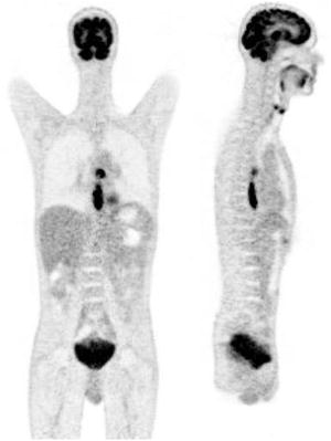

Fig. 4.4
Example of coronal (left) and sagittal (right) slices of a 18F-FDG PET whole-body image. The image demonstrates increased focal uptake in an esophageal lesion and a mediastinal lymph node. Normal physiological uptake is seen in the brain and bladder
Besides oncology, the other major applications of PET are cardiology [35] and neurology [36], as well as preclinical research with scanners dedicated to small-animal imaging [37]. Other less frequent applications include imaging of gene expression, assessment of infectious disease, and pulmonary function.
4.3.2 Architecture of PET Systems
When two 511 keV photons reach the detectors nearly simultaneously (coincidence detection), a positron annihilation is assumed to have occurred somewhere along the line between the two detectors—this line is called line of response (LOR) and is actually a parallelepiped when the finite width of the detectors is taken into account. Therefore, no physical collimators are required in PET, but the collimation is done electronically, by considering only pairs of photons reaching the detectors nearly simultaneously.
For coincidence detection, at least two opposing sets of detectors must be used. All modern commercial PET scanners (actually hybrid PET/CT scanners, since standalone PET scanners are obsolete) extend this concept by using static rings of detectors placed around the patient. For whole-body scanners the detectors are typically arranged in a gantry of about 70–80 cm diameter.
The detectors are composed of scintillator crystals coupled to photodetectors; the formers convert the incoming photon into light, which is then transformed into an electrical signal. Regarding the scintillators, crystals such as BGO, LSO, LYSO, or GSO are currently used, cut in blocks with a small surface facing the patient (e.g., 4 × 4 mm2) and deep enough to detect most 511 keV photons (usually 20-mm depth). For the light readout, photomultiplier tubes are generally used as photodetectors. As the photomultiplier tubes are bulky and small crystals are needed to achieve a high spatial resolution, the coupling between the scintillator and the PMT is not done one-to-one for most clinical scanners but rather in a block design with, for example, a matrix of 8 x 8 crystals coupled to only four photomultiplier tubes. The signal between neighboring PMTs is compared using a coding scheme to determine the scintillator crystal of interaction [38].
Such detectors allow the measurement of the time at which the incoming photon was detected (with the accuracy provided by the time resolution) and the energy which was deposited in the detector (with the accuracy provided by the energy resolution). If the energy deposited is not within a given energy window, for modern clinical scanners usually with a lower threshold of 400–450 keV and a higher threshold of 600–670 keV, the photon is assumed to have undergone Compton scatter and is discarded for further processing. If the energy deposited is within the predefined window, a coincidence window is open: if a second photon with suitable energy is detected within the time defined by the coincidence window, both photons are said to be in coincidence and are considered to arise from the same positron annihilation somewhere along the LOR between the two detectors (see Fig. 4.5a). If the annihilation does not occur at the center of the LOR, the two photons will reach the detectors at a slightly different time; this difference can be as much as 3 ns for annihilations in whole-body scanners (~70 cm diameter with photons moving at the speed of light). Therefore, the coincidence window is typically defined to be about the summation of this time and twice the time resolution of the detectors.
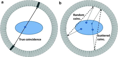

Fig. 4.5
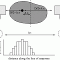
Coincidences in a PET scanner shown in a 2D ring of detectors. On the left (a), a true coincidence is described: an annihilation event produces two collinear 511 keV photons which move in opposite directions and are detected within a short time window by two detectors; the annihilation event is correctly assigned to be somewhere along the LOR between the two detectors. On the right (b), random and scatter coincidences lead to incorrectly assigned annihilation events (dashed lines corresponding to assumed paths of the photons, dotted lines corresponding to real paths of the photons). The random coincidence corresponds to two unrelated annihilation events with only one photon detected for each (because the other photon is absorbed by the patient, is not stopped by the detectors, or goes outside the axial field-of-view of the scanner in 3D). The scattered coincidence corresponds to the detection of two photons originating from the same annihilation, but at least one of them is scattered on its way losing part of its energy but still being accepted by the predefined energy window
The performance of a PET scanner depends strongly on the energy and time resolution of the detectors. If the energy resolution is low, the lower energy threshold must be set to a small value in order to correctly identify most 511 keV photons, but many scattered events will also be accepted (see Fig. 4.5b) [39]. Similarly, two drawbacks are associated with a low time resolution: first, the random detections are increased (Fig. 4.5b), that is, more unrelated photons from different annihilations are considered to be in coincidence degrading the image quality; second, less activity can be present in the field of view (FOV) before photons from different annihilations are detected within the coincidence window (the scanner enters saturation earlier). Another advantage of having detectors with high time resolution is the possibility to perform time-of-flight measurements (see Chap. 3, Sect. 3.5.4).
State-of-the-art clinical PET scanners achieve a spatial resolution of about 4 mm, energy resolution of about 11.5 %, and time resolution of about 550 ps. More detailed information about performance evaluation of PET scanners is available in [40].
4.3.3 Principles of PET Data Acquisition
The rings of detectors in clinical PET scanners cover an axial range of 15–22 cm. This is sufficient for single-organ imaging (e.g., brain and cardiac imaging). In oncology, multi-bed acquisitions are usually performed for partial-body or whole-body imaging, following a step-and-shoot acquisition mode. In difference to SPECT, the shoot phase here is the acquisition of a complete 3D image limited only in its axial FOV, and each step is an axial movement of the patient bed. To account for the decrease of sensitivity at the border of the axial FOV, the bed positions are acquired with some overlap; alternatively, continuous bed motion has been suggested [41, 42] but is not yet commercially available. In the multi-bed step-and-shoot acquisition, as usually practiced in whole-body oncology imaging, an acquisition time of 1–4 min per bed position is typically used, depending on the sensitivity of the scanner, the patient weight and the injected dose (taking into account the radioactive decay until the acquisition).
At this point, it is important to understand the role of photon attenuation. Actually, the majority of the 511 keV photons interact with the patient’s body, so that only a small fraction is detected–for the inner part of the abdomen, this fraction can be below 5 %. In order to account for this effect and create quantitative PET images, attenuation correction must be performed (Fig. 4.6) [43]. For this purpose, an attenuation map is needed with the linear attenuation factor μ at 511 keV for each voxel. The attenuation factor for each LOR is then determined by integrating the attenuation factor over the LOR: the attenuation is independent of the place along the LOR where the annihilation event took place, because the joint trajectory of the two back-to-back photons is the complete path between the detectors.
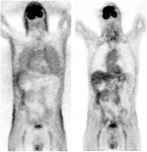

Fig. 4.6
Coronal slice of a 18F-FDG PET whole-body image reconstructed without (left) and with (right) attenuation correction. The activity distribution in the image without attenuation corrected is distorted, creating an apparent contrast between the skin and the inner structures and a false increased uptake in the lungs
Therefore, in addition to measuring the photons resulting from the positron annihilations within the patient, an attenuation map is routinely acquired. The acquisition of the attenuation map in standalone PET scanners (now obsolete) was typically done using a rotating radionuclide source, requiring a few additional minutes per bed position. This is not the case anymore for hybrid PET/CT scanners, where the CT image (acquired in a few seconds) is used for this purpose. Whole-body 18F-FDG acquisitions in state-of-the-art PET scanners (hybrid PET/CT) typically last 5–15 min.
As described for SPECT, in PET it is also possible to perform listmode acquisitions and reconstruct gated or dynamic images. In oncology, respiratory gating has been shown to facilitate better tumor delineation and more accurate uptake quantification for thoracic lesions [44]. The disadvantage of this approach is that an extended acquisition time is needed in order to achieve good image quality for each gate. For cardiac imaging, ECG gating is usually performed, and the possibility of performing dual cardiac-respiratory-gated acquisitions has been investigated [45]. Moreover, PET is well suited for dynamic acquisitions because of its high sensitivity. Some physiological parameters can be quantified in absolute terms by analyzing dynamic images with appropriate kinetic modeling. One example is the use of dynamic acquisitions to determine the absolute myocardial blood flow [46].
As in SPECT, the image reconstruction (discussed in a later chapter) has a big impact on the resulting PET images. Besides the algorithm and parameters used, the implementation of different corrections (for attenuation, scatter, randoms, detector normalization, and dead time) also plays an important role.
4.3.4 Improvements in PET Technology
In the last two decades, PET underwent major technological improvements. We list below the most important ones, excluding changes specific to hybrid PET/CT and PET/MR scanners:
New scintillators. From 1980 through the year 2000, bismuth germanate (BGO) was typically used in PET as scintillation crystal. Since then, a new generation of scintillators (including LSO, LYSO, and GSO) demonstrated better performance, combining a high stopping power with decay times much shorter than the ones for BGO. These scintillators were better suited for high count rates and 3D acquisitions.
3D acquisition. Physical collimators (tungsten septa) were previously used in PET to isolate each ring of detectors from the neighbors in order to acquire only in-plane events and avoid detection of oblique photons, referred to as 2D acquisition. Nowadays, PET systems acquire in 3D mode without septa and thus achieve a dramatic increase in sensitivity as compared to 2D acquisition.
Smaller crystals. The spatial resolution of a PET system depends strongly on the size of the scintillator crystals. Most modern PET (PET/CT) systems use crystals with a face of 4 × 4 mm2 and depth of 20 mm. Yet, the crystals cannot be made indefinitely small because of the associated loss of volumetric sensitivity.
New radiotracers. Many new radiotracers targeting relevant physiological processes have been developed in PET in recent years. Some of them are already clinically used, and others await authorization for clinical use and might reach the market in coming years. These new radiotracers have a deep impact on the clinical use of PET.
Iterative reconstruction. As in SPECT, there has been a shift from filtered backprojection to iterative reconstruction. Currently, the most commonly used reconstruction in PET is the ordered-subsets expectation maximization algorithm. The implementation of the iterative reconstruction is recently changing from 2D (after data rebinning) to fully 3D reconstruction, supported by the increasing computing power. Resolution recovery techniques are also gaining popularity, which partially compensate the decrease of resolution at the outer part of the FOV.
Time-of-flight. When recording a coincidence event, it is only possible to conclude that an annihilation took place somewhere along the line between the two detectors. If the detectors could resolve the exact arrival time of the photons and by assuming perfect collinearity, it would be possible to precisely localize the location of the annihilation. Recent commercial scanners with fast scintillators and electronics can reach time resolutions below 1 ns, so that the annihilation can be localized down to only a line segment instead of the complete line (e.g., for 500 ps time resolution, the annihilation is located within a 7.5-cm line segment). This technique, known as time-of-flight, results in a significant increase of image quality [47]. With the advent of new photodetectors [48], further improvement of the time resolution is expected. Using digital silicon photomultipliers, it has been shown that a time resolution below 200 ps can be achieved [49].
4.3.5 PET Versus SPECT
PET and SPECT share many similarities in that they both perform functional imaging by means of radioactive probes. However, they also have a number of differences.
Isotopes involved. Although a SPECT scanner can in principle measure the 511 keV photons resulting from a positron-emitter (used in PET), they are optimized for radioisotopes which do not involve positron emission and directly result in the emission of a gamma ray, typically in a lower energy range (e.g., 210Tl at 70 keV, 99mTc at 140 keV). Positron-emitters used in nuclear imaging have a half-life between 1 min and 2 h and can often be incorporated by replacement into light molecules naturally present in the organism (e.g., 15O–H2O). Isotopes clinically used in SPECT usually have a longer half-life (from 6 h for 99mTc to 3 days for 201Tl or 59 days for 125I) and often can be incorporated only to radiotracers with a high molecular weight which are not naturally present in the organism. The difference in half-lives has a direct impact on their clinical use. PET is ideally suited to study rapidly changing physiological processes because the radiotracers decay quickly. SPECT is better adapted for the study of slower processes and allows imaging hours or even days after tracer administration. Moreover, isotopes with different energies can be simultaneously used and discriminated from each other in SPECT, making dual-isotope imaging possible [50].
Sensitivity. The coincidence detection used in PET allows a much higher sensitivity as compared to the physical collimation used in SPECT, which rejects a large majority of the incoming photons. The sensitivity of PET is about two orders of magnitude that of SPECT; therefore, in PET less radiotracer is often needed to measure a physiological process, and the acquisition can be done in less time.
Spatial resolution. The spatial resolution in PET is limited by two fundamental physical limits: the positron range and the photon acolinearity (see Chap. 3, Sect. 3.5.2). Conversely, the spatial resolution of SPECT is only limited by the resolution of the detectors, so that a very high spatial resolution is theoretically possible. However, the necessary compromise in SPECT between sensitivity and resolution changes this fact, so that in clinical systems the opposite is true: current clinical PET scanners reach a spatial resolution of 4–5 mm, whereas SPECT scanners typically deliver a notably worse resolution of 8–10 mm. High-resolution (<1 mm) SPECT acquisitions at the expense of low sensitivity are sometimes used in small-animal imaging. The resolution of PET in small-animal imaging is about 1.5–2 mm.
Attenuation correction. Correction for photon attenuation is more accurate in PET than in SPECT, where it still represents an exception to perform such a correction. In PET, the detection of two photons at opposing detectors allows an exact attenuation correction: the attenuation factor used for the correction is the integral of the attenuation between the two detectors independent of the location of the annihilation event, because the joint trajectory of the two back-to-back photons is the complete path between the detectors. Attenuation correction is routinely performed in PET and is a critical step to obtain images quantifiable in absolute activity units. In SPECT, it is much more challenging to accurately correct for photon attenuation because photons originated at different depths will suffer different attenuation patterns. There is still controversy about the clinical benefit of attenuation correction in SPECT [51], and most SPECT systems do not yet include mechanisms to measure the tissue attenuation. The lack of attenuation correction leads to artifacts which makes the image interpretation more difficult.
Stay updated, free articles. Join our Telegram channel

Full access? Get Clinical Tree


