KEYFACTS
 Commonly a fatal injury caused by rupture of craniocervical ligaments (tectorial membrane, cruciate, apical, and alar ligaments) due to rapid deceleration with hyperflexion or hyperextension of the head.
 It is more common in children due to large size of head.
 To assess the space between the base of skull and Cl, the best and easiest measurement is “basion-dental interval” (inferior tip of clivus to top of odontoid process), and normally, this space should not exceed 12 mm in children or adults.
 Magnetic resonance imaging (MRI) shows injuries to the brain stem in a significant number of these patients. If tectorial membrane is torn, injury is nearly always fatal.
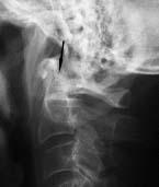
FIGURE 25-1. Lateral radiograph shows increased basion-dental distance (arrow).
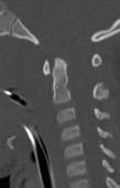
FIGURE 25-2. Midline CT reformation, in a different patient, shows marked increased basion-dental distance.
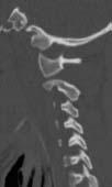
FIGURE 25-3. Parasagittal CT reformation, in the same patient, shows separation of the occipital condyle from lateral mass of C1.
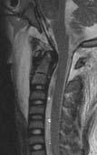
FIGURE 25-4. Midsagittal T2, in a different patient, shows cranio-cervical separation with intact tectorial membrane and a normal-appearing spinal cord.
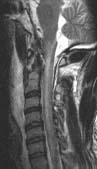
FIGURE 25-5. Midsagittal T2, in a different patient, shows cranio-cervical separation with torn tectorial membrane and spinal cord edema.
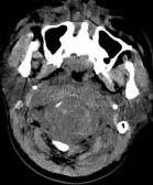
FIGURE 25-6. Axial computed tomography (CT), in a different patient, shows absence of normal bone structures at level of the cranio-cervical separation and significant swelling of all soft tissues.
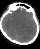
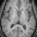
FIGURE 25-7. Axial CT, in the same patient, shows diffuse cerebral edema.
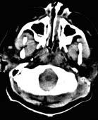
FIGURE 25-8. Axial CT, in a different patient with cranio-cervical separation, shows dense blood around cord.
SUGGESTED READINGS
Harris JH, Carson GC, Wagner LK: Radiologic diagnosis of traumatic occipitovertebral dissociation: 1. Normal occipitovertebral relationships on lateral radiographs of supine subjects. Am J Roentgenol 1994;162:881–886.
Harris JH, Carson GC, Wagner LK: Radiologic diagnosis of traumatic occipitovertebral dissociation: 2. Comparison of three methods of detecting occipitovertebral relationships on lateral radiographs of supine subjects. Am J Roentgenol 1994;162:887–892.

KEYFACTS
 Most common fracture of Cl, caused by axial compression.
 Jefferson type fracture results in bilateral fractures of anterior and posterior arches but may be unilateral if the head is tilted upon impact.
 Generally there is no spinal cord damage because the canal diameter is not significantly compromised.
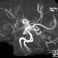
 Vertebral arteries may be damaged.
 Fracture is unstable if lateral masses of Cl are separated from dens by >7 mm (implies torn transverse ligament).
 MRI helps to establish status of transverse ligament; if avulsed at bony insertion, patients do not need immediate surgery as healing occurs in > 60%; if the substance of the ligament is torn, surgical fixation is needed.
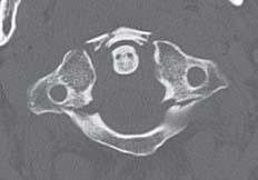
FIGURE 25-9. Axial CT shows fractures involving the anterior and posterior arches of Cl Note. that lateral masses of C2 are more than 7 mm apart from dens indicating torn transverse ligament.
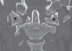
FIGURE 25-10. Coronal CT reformation, in the same patient, shows outward displacement of the lateral masses (stars) of C1.
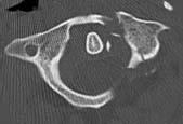
FIGURE 25-11. Axial CT, in a different patient, shows left-sided fractures of C1.
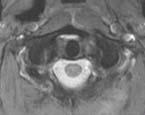
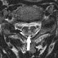
FIGURE 25-12. Axial magnetic resonance (MR) T2, in the same patient, shows that the transverse ligament is avulsed at both of its insertions.
SUGGESTED READING
Lustrin ES, Karakas SP, Ortiz AO, Cinnamon J, Castillo M, Vaheesan K, et al. Pediatric cervical spine: normal anatomy, variants, and trauma. Radiographics 2003;23:539–560.

KEYFACTS
 They are the most common fractures of C2.
 Type 1 occurs through the tip of the dens, is the least common type and stable, and may be confused with an os odontoideum.
 Type 2 is the most common type and involves the base of the dens; it may be missed on axial CT; therefore, plain radiographs and sagittal or coronal CT reformations are mandatory; in adults, this fracture disrupts the blood supply, and there is a high incidence of nonunion.
 Type 3 extends from the base of the dens to the body of C2; if it extends into articular facets, the prognosis worsens.
 Os odontoideum refers to the lack of assimilation of an occipital vertebra or a hypertrophied ossiculum teminale; it is always accompanied by hypoplasia of remaining dens and may have hypoplas-tic anterior and/or posterior arches of Cl and C1-C2 instability.
 Vertical fractures are rare type of injury to the dens.
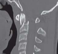
FIGURE 25-13. Midsagittal CT reformation shows a type 2 dens fracture and anterior displacement and angulation of the odontoid process.
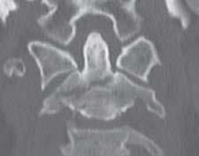
FIGURE 25-14. Coronal CT reformation, in a different patient, shows a type 3 dens fracture extending to the body and right lateral mass of C2.
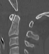
FIGURE 25-15. Midsagittal CT reformation, in a different patient, shows a nondisplaced type 2 dens fracture.
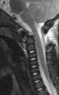
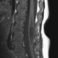
FIGURE 25-16. Midsagittal T2 in a child shows type 2 fracture with anterior displacement of dens and torn tectorial membrane.
SUGGESTED READING
Sasso RC. C2 dens fractures: treatment options. J Spinal Disord 2001;14:455–463.

KEYFACTS
 This fracture of both C2 pedicles is secondary to hyperextension, compression, and distraction, which may produce instant death secondary to spinal cord transection.
 Avulsion of anterior aspect of end-plates of C2 and C3 may be present.
 Pedicle fractures are usually bilateral, but asymmetrical fractures may extend to lamina, facets, or vertebral body.
 Grade 1: minimal distraction; only anterior longitudinal ligament is torn. Grade 2: moderate distraction and angulation; anterior and posterior longitudinal ligaments are torn; and disc hernia-tion occurs. Grade 3: significant distraction; tearing of most of ligamentous complex, epidural and spinal cord hematomas, vertebral artery injuries, and disc herniation.
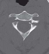
FIGURE 25-17. Axial CT shows fractures through the pedicles of C2.
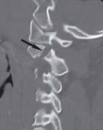
FIGURE 25-18. Parasagittal CT reformation, in the same patient, shows the fracture (arrow) in one of the pedicles.
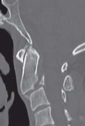
FIGURE 25-19. Midsagittal CT reformation, in the same patient, shows anterior subluxation of C2 on C3 and a posterior inferior corner avulsion fracture.
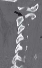
FIGURE 25-20. Oblique CT reformation, in a different patient, shows C2 pedicle fracture (arrow).
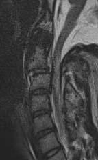
FIGURE 25-21. Midsagittal T2, in a different patient, shows anterior subluxation of C2 with disruption of the anterior and posterior longitudinal ligaments and cord edema.
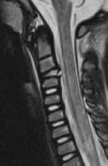
FIGURE 25-22. Midsagittal T2 in a child with anterior C2 tilting, a disrupted posterior longitudinal ligament, and cord edema.
Related posts:
Stay updated, free articles. Join our Telegram channel

Full access? Get Clinical Tree


