Among the four X-ray fluoroscopy systems, two sets are selected to view the gold marker in the patient body. The marker is first located within each digital image via a template matching (TM) algorithm. The image processor compares the digitized image and the template image of the marker by using a correlation function. The marker position is assumed to be the location with the maximum pattern recognition score (PRS). If the PRS is less than a predefined value, the fluoroscopic RTRT system halts the linac operation. If the PRS is above the predefined value and the position is within the gating window, the linac is triggered to irradiate the tumor. When the marker moves outside the gating window, the beam is turned off. The PRS between the search area and template are displayed on the CRT every 0.03 s (Shirato et al. 2000a).
Shirato et al. (2000a, b) showed in a phantom experiment that the coordinates of the marker were detected with an accuracy of +/− 1 mm (Shirato et al. 2007). Similarly, in the moving targets, the geometric accuracy of the tumor tracking system was found to be better than 1.5 mm up to a speed of 40 mm/s, which is much better than the external surrogate approach. The RTRT system significantly improves the accuracy of irradiation of the target in motion at the expense of an acceptable amount of diagnostic X-ray exposure (Shimizu et al. 2001).
Shimizu et al. (2001) treated four lung cancer patients with the RTRT system and found that the range of the marker during the beam on period was reduced to within 5.3 mm in all directions (Shimizu et al. 2001). Kitamura et al. (2002) suggested that the RTRT system was useful in prostate cancer for reducing uncertainty due to the effects of the respiratory cycle, especially with the patient in the prone position (Kitamura et al. 2002). Yamamoto et al. (2004) used the RTRT system for patients with gynecology malignancies. The PTV margin with three gold marker setup reduced by 3.3 mm, 6.1 mm, and 4.6 mm with respect to manual setup, which indicated that RTRT was useful to reduce the PTV margin and to perform 3DCB (Yamamoto et al. 2004). Similarly, in RTRT-based head and neck treatment, Oita et al. (2006) concluded that the setup error in RL, CC, and AP directions was reduced by 1.6 mm, 1.3 mm, and 0.8 mm, respectively, with respect to manual setup (Oita et al. 2006). Ahn et al. (2004) applied the RTRT system for unresectable pancreatic cancer. The average movements of markers in RL, CC, and AP directions were 3.0 mm (range 1.7–5.2 mm), 5.2 mm (range 3.5–6.8 mm), and 3.5 mm (range 2.7–5.1 mm), respectively (Ahn et al. 2004).
As there are limitations in any system, the present RTRT system also has shortcomings. First, the major uncertainty of the system is the migration of the implanted markers. Second, as the tracking method requires invasive marker implantation, there is a risk of pneumothorax (Abdefg et al. 2002; Geraghty et al. 2003). Finally, the system irradiates only when the tumor is within the gating window, thus a duty cycle of no more than 20–30 % leads to long treatment time (Depuydt et al. 2011).
11.2.2 Electromagnetic Tracking
Electromagnetic tracking is another real-time tumor tracking modality and has many benefits over the use of simple gold markers (Balter et al. 2003; Balter et al. 2005). The main advantages are (1) no requirement of ionizing radiation during localization, (2) the target isocenter may be monitored continuously at the frequency of 10 Hz during radiation delivery rather than once at the beginning of each fraction, and (3) real-time feedback is provided so that action may be taken to limit the influence of intrafraction motion (Litzenberg et al. 2007). Research shows that the complication rates of gold marker and transponder implantation are similar (Willoughby et al. 2004; Pouliot et al. 2004). The use of electromagnetic technology was first elaborated for stereotactic radiotherapy localization utilizing a wired transponder sensor (PV et al. 1992). Position tracking systems used in image-guided surgery using a wired transponder are Aurora and microBird (Hummel et al. 2002). Similarly, a miniature implantable radiofrequency (RF) coil (8 mm x 0.8 mm) was proposed by Seiler et al. (2000). The coil can be tracked magnetically in 3D in real time (Seiler et al. 2000). Currently, a novel wireless electromagnetic localization system, Calypso 4D Localization System (Calypso Medical, Seattle, WA) has been developed for real-time tracking in radiotherapy (Balter et al. 2003).
The major components of the Calypso 4D Localization System are shown in Fig. 11.2, which include (1) a mobile AC electromagnetic console; (2) a receiver array; (3) three ceiling-mounted infrared optical cameras and a hub, all located in the treatment room; (4) wireless transponders (8 mm × 2 mm) (Beacons); and (5) a tracking station in the control area (Balter et al. 2005). The array contains four source coils and 32 receiver coils. The source coil generates an electromagnetic field in the 300 to 500 kHz frequency range which induces a resonance in the transponder. The spatial coordinates of the transponder are determined from the treatment-planning CT scan and the offset between the transponder centroid, and the intended isocenter is updated at a rate of 10 Hz.
The Calypso system can be used in two ways: localization and tracking. When a patient is planned for radiotherapy, no fewer than two transponders are first implanted into the tumor region. The patient then undergoes thin CT simulation after 4–14 days. Transponder coordinates on the CT scan relative to the treatment plan isocenter are calculated and entered into the Calypso system. The Calypso receiver is placed over the patient, and its position relative to the isocenter, as well as the transponder position relative to the array, is determined. Transponders are excited by an external field generated by the array and emit an electromagnetic signal at one of the three unique resonance frequencies which is detected and localized by an electromagnetic array placed above the patient (Mayse et al. 2008). Several sensors are placed inside the array which measures the strength and orientation of the resonant signal from the transponders. The data is then transferred to a manufacturer-provided software to determine and continuously monitor the target position with respect to the array. For continuous tracking, the transponder must be placed 23 cm or less from the detection array above the patient (Quigley et al. 2009). Infrared cameras continuously monitor the array’s position relative to the linear accelerator which helps to calculate the position of the target with respect to the linear accelerator’s isocenter. In this way, the electromagnetic system serves as a kind of Global Positioning System (GPS), and hence this system is often referred to as “GPS for Body.”
A phantom experiment showed that submillimeter accuracy was maintained using the electromagnetic tracking technique (Balter et al. 2005). A clinical evaluation showed a comparable localization accuracy to the isocenter (within 1.5 mm) compared with X-ray localization (Burch et al. 2005; Kupelian et al. 2005; Willoughby et al. 2006). Similarly, the root mean square (RMS) accuracy of this system for real-time verification of 4DCT data has been shown to be 0.28 mm (maximum error 1.2 mm) (Parikh et al. 2005). Similarly, the time lapse between the Calypso readout and X-ray imaging was approximately 8 min, and the patient localization accuracy (difference between the Calypso system-predicted transponder location and the radiographic system-predicted transponder position location) was within 1.5+/− 0.9 mm in research carried out by multiple institutions (Santanam et al. 2008).
The initial US Food and Drug Administration (FDA) approval in July 2006 allows for the Calypso system to be used in the treatment of prostate cancer only. Kupelian et al. reported that the difference between the skin marker and Calypso alignment was greater than 5 mm in more than 75 % of all fractions (Kupelian et al. 2007). Similarly, Quigley et al. showed the patient positioned with conventional tattoos and laser to have alignment error exceeding 5 mm when compared with the Calypso positioning and monitoring system (Quigley et al. 2009). Litzenberg et al. showed that the margins required to account for intrafraction motion were around 2 mm in all directions considering that 90 % of patients received 95 % of the prescribed dose using the Calypso system, but in the absence of this system, the margins are 10 mm (Litzenberg et al. 2007). This shows that a significant reduction in margin is possible using the Calypso system.
11.2.3 Combined MV/kV Imaging System
The feasibility of using electronic portal image devices (EPIDs) for real-time tumor tracking has recently been explored (Keall et al. 2004). However, since only a single in-line MV is used, this approach suffers from insufficient information to completely determine the 3D coordinates of the implanted fiducials. The combined use of MV treatment beams with kV projection images has recently been proposed (Wiersma et al. 2008). Unlike other fluoroscopy tracking systems which require two or more additional kV X-ray imaging sources for obtaining spatial information, the system uses the treatment beam and only one kV X-ray imaging source as shown in Fig. 11.3.


Fig. 11.3
Varian Trilogy with KV and MV imager, with KV beam and MV beam perpendicular to each other (Modified from Wiersma et al. 2008)
Wiersma et al. demonstrated a real-time 3D internal fiducial tracking system based on the combined use of MV and kV imaging systems. The Varian Trilogy system (Varian Medical Systems, Palo Alto, CA) with kV and MV imagers operating in the 6 MV photon mode was used for this study. MV beam images were obtained using an aSI EPID (Portal Vision MV AS-500, Varian Medical Systems, Palo Alto, CA), and the kV imaging was acquired using an onboard kV imaging system located perpendicular to the treatment beam. Two channels of a four-channel PCI video grabber (Pro Video 149P, ProVideo Co., Taipei, Taiwan) were used to grab the kV and MV video streams at 30 fps per channel with a resolution of 640 × 480 pixels. To analyze the video, software was used with a sequence of filters for detecting the fiducials.
The geometrical accuracy of the system was found to be on the order of 1 mm in all three spatial directions. With this tracking system, the MV trace lags behind the kV trace by approximately 70 msec. Moreover, the system is intensity based in nature; thus, when the fiducial moves in the vicinity of high-density objects such as the bone that can have similar intensity values as the fiducial, the tracking becomes difficult or even impossible.
11.3 External Surrogate Tracking System
The external surrogate tracking system is a respiratory gating technology which is based on the correlation between the tumor position and the patient’s respiratory cycle. The most available and widely discussed respiratory gating system utilizing external respiration signal is the Real-time Position Management (RPM) system (Varian Medical Systems, Palo Alto, CA). By measuring the patient’s respiratory pattern and range of motion, the system software creates a graphical sinusoidal form (waveform) as a function of time. The major components of the RPM system are a marker block, an infrared tracking camera, and a predictive filter. The marker block is a plastic box with two or six reflective dots on one side and serves as the external fiducial marker. The marker is placed on the patient’s anterior abdominal surface, usually between the umbilicus and the xiphoid because this region has been shown to yield the largest amplitude in maker motion (typically 1–2 cm) (Fig. 11.4) (Mageras et al. 2001). It should be placed nearly horizontal and at the same location during imaging for planning, simulation, and treatment. The camera is a charge-coupled device (CCD) with an array of LEDs that emits infrared light. Dots on the marker block reflect the infrared light back to the camera, which captures the signal. The system software then utilizes this signal to track and analyze the motion of the dots, which corresponds to the motion of the chest or abdomen. The predictive filter is a vital part of the RPM software which detects and predicts the patient’s breathing pattern. After recognizing the pattern, the predictive filter makes sure that this pattern is being followed. If there is any interruption in the breathing pattern, the predictive filter detects the interruption, and RPM instantly turns the beam off.


Fig. 11.4
Berson et al. from September 2000 to January 2002 evaluated RPM on 108 patients (lung, liver, breast, mediastinum) and concluded that the system is a practical and achievable solution for minimizing respiratory-induced target motion during both simulation and treatment (Berson et al. 2004). Ford et al. found that the residual intra- and interfraction movements measured by fluoroscopic and portal imaging using this technique were 2.6+/− 1.7 mm and 2.8 +/−1.0 mm, respectively. With no gating, the intrafraction excursion became 6.9+/−2.1 mm (Ford et al. 2002). In research carried out by Wagman et al., ten patients with liver tumors were treated using the RPM system. Average superior-to-inferior (SI) diaphragm motion on initial fluoroscopy was reduced from 22.7 mm without gating to 5.1 mm with gating (Wagman et al. 2003). Similarly, reproducible decrease in liver motion with gating reduced the GTV-to-PTV margin from 2 cm to 1 cm and resulted in a dose increase of 7–27 % (median 21.3 %) in six patients. Underberg et al. evaluated 4D CT scans on 31 lung tumor patients; the mean mobility vector decreased from 8.5 +/− 6.5 mm for the entire breathing cycle to 1.4 mm +/− 0.7 mm in the tidal-expiration gated window (Underberg et al. 2005).
Other gating devices have also been used for external surrogate tracking, such as pressure-sensitive belts (Li et al. 2006). Similar to the positioning of the RPM marker block (Fig. 11.4), a pressure sensor is placed on the abdomen. The belt detects the abdominal motion (both amplitude and phase) by measuring pressure variation and then transfers the motion signal to the monitoring station. The software records the patient’s respiratory data and controls the irradiation beam accordingly. However, as in the external surrogate systems, the relationship between the external surrogate and the internal tumor motion seems to vary, even during treatment on the same day (Lin et al. 2009). This approach is therefore often considered to suffer from lack of accuracy.
11.4 Internal and External Surrogate Tracking System
11.4.1 Direct Tumor Tracking System
An RTRT system in which the beam is continuously delivered pursuing the position of the tumor is known as non-gated RTRT or dynamic tracking radiotherapy (DTT). Mitsubishi Heavy Industries in collaboration with Kyoto University and Brain LAB (Feld Kirichen, Germany) developed the DTT system, also referred to as Vero (Fig. 11.5) (Mukumoto et al. 2012). It is composed of a small and light 6MV C-band linac mounted on a gimbaled X-ray head with MLC. The entire system is installed on an O-ring gantry (Takayama et al. 2009). The X-ray head can rotate in both horizontal and vertical axes relative to the O-ring direction to track a moving target. The imaging system, which is fixed in the gantry, consists of two types of imaging systems, each consisting of a kV X-ray tube and a flat panel detector (FPD) with an infrared IR camera mounted on the ceiling of the treatment room.
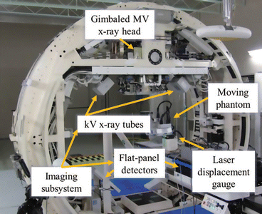

Fig. 11.5
Dynamic tumor tracking DTT system (Vero system) with gimbaled MV X-ray head and KV X-ray tubes (Mukumoto et al. 2012)
IR markers are placed on the surface of patient’s abdominal wall for detecting respiratory signal, and fiducial markers are implanted in the tumor and are continuously and simultaneously monitored using the IR camera and the orthogonal kV X-ray imaging system. After tracking, a correlation model (4D) is developed using the detected respiratory signals and the position of the moving marker (Suzuki et al. 2014). In the 4D model, the peak-to-peak amplitude of the detected target motion, mean, and the standard deviation between the moving position and the IR marker are calculated automatically (Mukumoto et al. 2013). Then using the gimbal mechanism, the therapeutic X-ray beam tracks and follows the real-time position of the tumor and delivers therapeutic X-rays continuously, while the beam is tracking the moving tumor until the prescribed dose is completely delivered. According to Tom Depuydt et al., the systematic tracking error of the Vero system was found to be below 0.14 mm. Similarly, the sinusoidal motion tracking was found to be accurate with a tracking error of 90 % percentile E 90% <0.82 mm (Depuydt et al. 2011).
In 2011, the world’s first DTT was performed on a lung cancer patient using Vero 4DRT at Kyoto University Hospital (Suzuki et al. 2014). Matsuo et al. (2014) performed DTT on a lung cancer patient using a gimbal-mounted linac. The tracking plan showed PTV volume reduction from 56.2 cm3 to 39.6 cm3 covering 95 % of the GTV. Dose to the normal lung and liver were also reduced (Matsuo et al. 2014).
11.4.2 Respiratory Tracking System (RTS)
The Synchrony™ Respiratory Tracking System (RTS) is a subsystem of the CyberKnife robotic treatment device (Accuray Inc., Sunnyvale, CA). It is used to irradiate extracranial tumors that move due to respiration and is considered to be an external-internal tumor tracking modality. The main advantages of RTS are that the patients can breathe normally, and there is no loss of duty cycle such as with gated therapy systems. The duty cycle is generally 100 % (Seppenwoolde et al. 2007). Tracking is based on a measured correspondence model (linear or polynomial) between internal tumor motion and external (chest/abdominal) marker motion. The radiation beam follows the tumor movement via the continuously measured marker motion. The RTS uses computer simulation based upon the recorded external and internal marker positions which allow the robot to accurately follow tumor motion even in the case of irregular respiration signal. The correspondence model predicts tumor position and sends feedback to the robotic linear accelerator, and the robot realigns the beam with the tumor (Glide-Hurst and Chetty 2014).
The imaging system consists of two kV X-ray tubes and a pair of orthogonal positioned flat panel imagers. The internal marker (implanted at or near the tumor position) is determined via X-ray images. Similarly, three external markers, i.e., optical markers, are tracked using a light-emitting diode (LED) fixed on the chest or abdomen of the patient. A stereo camera system measures the 3D position of the markers continuously at 30 Hz (Hoogeman et al. 2009).
For the correlation mode, first the position of the internal marker is determined by X-ray fluoroscopy and is related to the external signal. Functions that are considered for establishing a correspondence model are linear model and polynomial model. The linear model is applied for the AP and LR directions and the polynomial model for the CC direction and for the phase shift and hysteresis in the trajectory (Hoogeman et al. 2009).
Misha et al. calculated residual error of the correlation model using the Synchrony treatment log file from 44 patients with 158 treatment fractions. The analysis included four log files. The files are comprised of image data, the time stamp of image acquisition, the center of mass (CoM) of the internal marker, and the correlation model for each component of motion and external marker separately. The correlation model error (e) was calculated for each X-ray image acquisition. If the value of e is greater than 5 mm, the system operation is halted, and a new model is generated by removing all existing data points and obtaining new sets of X-ray images. The operator takes X-ray images until the entire respiration cycle is included. Usually 6–8 images are needed for analysis.
The accuracy of the RTS calculated using the average and 95th percentile of 3D residual motion over each fraction phantom experiment showed that Synchrony performs real-time respiration motion tracking with an accuracy of 0.7 +/− 0.3 mm3 and suggested that irregular breathing, varying the phase relationship between internal and external markers and rapid baseline shifts, might reduce the clinical accuracy of respiratory motion tracking (Hoogeman et al. 2009). In the RTS, as the imaging is performed before each treatment, setup errors are virtually absent.
Research conducted by Seppenwoolde et al. showed eight lung cancer patients treated with the RTS (Seppenwoolde et al. 2007). The study found that the treatment errors due to breathing motion were reduced in all patients. The polynomial model was better for the patients having time delay between internal and external motion. Similarly, the residual treatment error was greater for fractions with more tumor motion.
The DTT and RT systems are both real-time beam-positioning methods, i.e., the treatment beam directly follows the tumor. Another method used for the same purpose is dynamic multi-leaf collimator (DMLC) tracking (Keall et al. 2005; Papiez et al. 2005; Rangaraj and Papiez 2005). In this system, once tumor motion is detected, the motion signal is transferred to the computer, and the software calculates the required leaf position to track the target based on the incoming signal (Keall et al. 2006a). The DMLC leaf travel speed can safely reach 2.5 cm/s, which is comparable with breathing-induced tumor motion speed (Giraud and Houle 2013).
Recently, positron emission tomography (PET) incorporated with linac has been proposed as one of the dynamic tumor tracking approaches (Darwish et al. 2010; Yamaya et al. 2011; Tashima et al. 2012). Tong Xu et al. implanted positron emission marker (PeTrack) and detected in real time using positron-sensitive detectors which is similar to PET (Xu et al. 2006). The computation time was less than 20 ms with less than 10 mm initial estimation error. Yamaguchi et al. studied m-IGRT by comparing the PET-based digitally reconstructed planar image (PDRI) registration with radiographic registration (Yamaguchi et al. 2011) and suggested that it is feasible for clinical use. Yang et al. proposed a center of mass (CoM) tumor tracking algorithm using gated PET images combined with respiratory monitor (Yang et al. 2014). The algorithm determines the target position information through the CoM of the segmented target volume on gated PET images reconstructed from accumulated coincidence events, which is continuously updated throughout a scan (Yang et al. 2014). The overall tracking error in phantom studies was found to be less than 2 mm.
11.5 Tumor Tracking Without Implanted Fiducials (Markerless Tracking)
11.5.1 Fluoroscopic Tracking
The fiducial implantation method involves the risk of pneumothorax as percutaneous marker implantation is involved and markers may also migrate (Jiang 2006). Many clinicians are thus reluctant to use this method. In order to overcome such effects, fluoroscopic tracking of the tumor without implanted fiducial markers has been developed (Berbeco et al. 2005a; Cui et al. 2008; Xu et al. 2007). Direct fluoroscopic tumor tracking is possible in the case of lung tumors since the density difference between the tumor mass and normal lung tissues may be large enough to provide a good visualization in radiographic images (Giraud and Houle 2013). The direct detection of a lung tumor in the kV X-ray image is possible if the tumor mass is small, well defined, and has a high-contrast edge (Berbeco et al. 2005a). However, it is extremely difficult to track tumors in the abdomen using this tracking procedure.
Stay updated, free articles. Join our Telegram channel

Full access? Get Clinical Tree


