Introduction
Ultrasound artifacts represent a false portrayal of image anatomy or image degradations related to false assumptions regarding the propagation and interaction of ultrasound with tissues, as well as malfunctioning or maladjusted equipment. Understanding how artifacts are generated and how they can be recognized is crucial, which places high demands on the knowledge of the sonographer and the interpreting physician. Most artifacts arise from violations of assumptions for creating the ultrasound image, including but not limited to (1) ultrasound travels at a constant speed in all tissues (1540 m/s); (2) ultrasound travels in a straight path; (3) reflections occur from the initial ultrasound beam with one interaction at a perpendicular incidence for each boundary; (4) attenuation of ultrasound echoes is uniform; (5) all of the energy emitted by the ultrasound transducer exists in the main beam; (6) the operator has transmit, receive gain, and other settings properly adjusted; and (7) all of the elements in the transducer array, as well as the remainder of the imaging system, are operating optimally.
Artifacts are caused by a variety of mechanisms that contradict the assumptions listed above. In respective order are responses to these assumptions: (1) Sound travels at different speeds in different media based on compressibility and density characteristics. The ultrasound system uses the average speed in soft tissue of 1540 m/s to map echo amplitude depths as a function of time in the image matrix. Most notably, for fat with a speed of 1450 m/s (about a 6% difference), echoes along the trajectory, including fat structures, are displaced farther in terms of depth from the actual location. (2) Even minor differences in ultrasound speed between tissues alter the transmitted beam direction from a straight-line trajectory when the incident ultrasound beam is nonperpendicular to the boundary, causing a change in wavelength (the ultrasound frequency remains constant in stationary tissues). The transmitted ultrasound beam is redirected at an angle of transmission different from the angle of incidence (known as refraction ), potentially causing mismapped anatomic locations. (3) Multiple reflections of ultrasound occur from all directions within the complex environment of the human body, complicating the mapping of anatomic boundaries in the ultrasound image. (4) Ultrasound attenuation varies greatly from high to low in typical tissues and structures encountered, with resultant artifactual shadowing or enhancement of tissues at greater depths in the image. (5) Transducer crystal expansion and contraction in the thickness mode produces the main ultrasound beam, but at the same time radial contraction and expansion also occur. This results in ultrasound energy emitted outside of the main beam producing echoes that can appear as if in the beam and creating false information in the image. (6) Improper use of user-adjusted overall receive-gain or time gain compensation (TGC) results in images that may not be representative of the acoustic properties at a given depth in the image. Pulse repetition frequency (PRF) settings must ensure adequate time for listening for echoes before the next pulse. Additionally, proper transducer frequencies must be selected to achieve the desired depth of penetration in the image. (7) The ultrasound system is dependent on all components of the imaging chain, including the transducer array, gain and filter settings, and image display, to be functioning normally. When there are component failures, the ultrasound images may not be accurately portrayed.
Fortunately, most ultrasound artifacts can be identified by the experienced sonographer because of obvious effects on the image or the transient nature of mismapped anatomy that appears and disappears during the scan. Some artifacts can be used to advantage as diagnostic aids in the characterization of tissue structures and composition. The following descriptions represent some typical artifacts encountered in diagnostic ultrasound.
Refraction
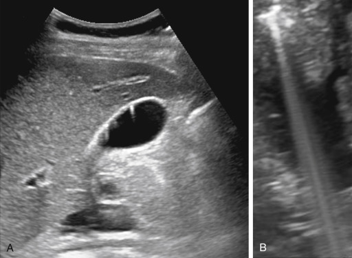
Refraction represents a change in the transmitted ultrasound pulse direction at a boundary with nonperpendicular incidence when the two adjacent tissues support a different speed of sound. Misplaced anatomy can occur in the image from the beam redirection as the echoes propagate back to the transducer over a similar return path ( Fig. 2.1A ). The sonographer must be aware of objects appearing and disappearing with slight differences in orientation of the transducer array. At the edges of smooth-rounded organs, refraction of the beam at nonnormal incidence can redirect the beam away from the edge, creating a shadow of reduced intensity beyond the edge and resulting in an edge artifact ( Fig. 2.1B ). In many situations, the cause of the refraction artifact can be traced back to anatomic structures.

Speed Displacement
The speed displacement artifact results from the substantial variability of sound speed in fat (1450 m/s) relative to soft tissues (1540 m/s)—about a 6% slower propagation speed. Anatomic borders are displaced distally when ultrasound interacts with structures containing fat compared with the nondisplaced borders through the soft tissues ( Fig. 2.2A ). In the situation of a soft tissue structure surrounded by a fatty liver, the border is proximally displaced behind the soft tissue structure ( Fig. 2.2B ). An image of a liver with a fatty region demonstrates a displacement and disruption of the distal border ( Fig. 2.3 ). The differences in speed also affect the accuracy of distance measurements along the direction of ultrasound travel when fat is present in the beam.


Shadowing and Enhancement
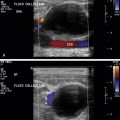
Acoustic shadowing is the result of several physical mechanisms. Objects with high attenuation, such as kidney stones and gallstones, can assist in diagnosis by producing shadowing or streaks ( Fig. 2.4 ), but they can also be a hindrance if a large attenuator, such as a rib, produces shadows that precludes optimal imaging of distal anatomy. Shadowing is also the result of reflection and refraction, as shown in the edge shadowing artifact in Fig. 2.1 . Acoustic enhancement occurs distal to low-attenuation, fluid-filled structures such as cysts and the bladder where increased transmission of sound occurs, resulting in distal hyperintense signals. “Through transmission” is commonly described for this occurrence.

Reverberation, Comet Tail, and Ring-Down
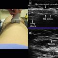
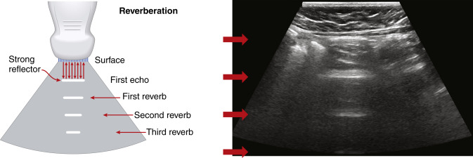
Reverberation artifacts arise from multiple echoes generated between highly reflective and parallel structures that interact at a perpendicular angle to the ultrasound beam. These artifacts are often caused by reflections between a reflective interface and the transducer or between reflective interfaces, such as metallic objects (e.g., bullet fragments), calcified tissues, or air pocket/partial liquid areas of the anatomy, and are typically manifested as multiple equally spaced parallel lines at progressive depth with decreasing amplitude ( Fig. 2.5 ). Comet tail artifact is a form of reverberation between two closely spaced reflectors and appears as bright lines along the direction of ultrasound propagation. It is manifested as a tapering shape and decreasing width with depth of travel ( Fig. 2.6A ). Reverberation artifacts are useful in assessing the characteristic structures of tissues but can also hinder visualization of deeper anatomy. Effects of reverberation can be reduced by adjusting the transducer angle of incidence or by decreasing the distance between the reflective structure and the transducer. Harmonic imaging reduces these artifacts by receiving the first harmonic frequency and filtering out the fundamental frequency.
Ring-down artifacts arise from resonant vibrations within fluid trapped between a tetrahedron of air bubbles, which creates a continuous sound wave that is transmitted back to the transducer and displayed as a series of parallel bands extending posterior to a collection of gas ( Fig. 2.6B ).
Mirror Image and Multipath Reflection
Mirror image artifacts occur when the ultrasound beam encounters a highly reflective nonperpendicular or curved boundary such as the diaphragm. The redirected beam encounters a specular reflector, producing a series of echoes that are reflected along the same path back to the transducer. As the field of view is scanned, the beam interacts with the same specular reflector to record its true position. Later echoes of the specular reflector from the redirected beam arrive and are mapped as distal objects on the opposite side of the strong reflector, appearing as a mirror image because of the double reflection. A common mirror image artifact occurs at the interface of the liver and the diaphragm in abdominal imaging. In one direction, the ultrasound beam correctly positions the echoes emanating from a lesion in the liver. As the ultrasound beam moves through the liver, echoes are strongly reflected from the curved diaphragm away from the main beam to interact with the lesion, generating echoes that travel back to the diaphragm and ultimately back to the transducer. The back-and-forth travel distance of these echoes creates artifactual anatomy that resembles a mirror image of the mass, placed beyond the diaphragm that would otherwise not have anatomy present in the image ( Fig. 2.7 ). Other strong reflectors that generate mirror image artifacts include the pericardium and bowel, which might be more difficult to detect due to the presence of other anatomic structures in the same area.