Ultrasound waves are defined as sound waves of high frequency that are inaudible to the ear. These are longitudinal waves that propel in a direction parallel to that of wave propagation in a medium.
High-frequency sound waves are inaudible to humans in the range of 2–20 million cycles per second (2–20 MHz)—this is the range of a diagnostic ultrasound.
Sound audible to humans is <20 KHz
Ultrasound is >20 KHz
Speed of sound in air is 330 meters per second
Speed of sound in fat is 1,450 meters per second
Speed of sound in soft tissue is 1,540–1,580 meters per second
Speed of sound in bone is 4,080 meters per second
Pulses of high-frequency sound waves are transmitted to the patient. Echoes returning from various tissue boundaries are detected. The received echo produces an ultrasound image (Figure 1.1).
Electricity converted into sound—Pulse
Sound converted into electricity—Echo
If more sound is received back—suggestive of stronger reflector—whiter image
If less sound is received back—suggestive of weaker reflector—blacker image
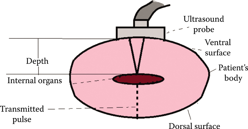
Figure 1.1 Illustrating principle of ultrasound.
Frequency: The number of cycles per second; measured in Hz (Hertz).
Wavelength: The distance between two consecutive waves. It depends on the frequency of waves and speed of propagation in the medium through which it is passing. It is inversely proportional to frequency.
Bandwidth: Range of frequencies produced by the transducer.
Pulse length: Small number of cycles in a pulse.
1. Transmitter: Sends voltage to energize the transducer.
2. Transducer:
3. Receiver: To detect and amplify weak signals and send them to display It controls the dynamic range and time-gain compensation (TGC).
4. Display: To present the USG image/data in a form suitable for analysis and interpretation.
The transducer’s input is communicated to scanner through a cable and the data can be visualized on the monitor.
Following are the ways through which spatial information can be displayed:
A mode: Amplitude mode; it is used for ophthalmic purposes
B mode: Brightness mode (gray scale, real time); it is used for routine sonography
M mode: Motion mode; it is used to measure the heart rate
Ultrasonography (USG) transducer is a device that converts electrical energy to mechanical energy and vice versa.
It has two functions:
1. Transmitter: Electrical energy is converted to acoustic pulse, which is transmitted to the patient.
2. Receiver: Receives reflected echoes. Weak pressure changes are converted to electrical signals for processing.
It is based on the principle of piezoelectricity.
Ultrasound pulses generated by transducer are propagated, reflected, refracted, and absorbed in tissues to provide useful clinical information.
Transducers (scanning probes) are the costliest part of any ultrasound unit.
The shape of the scans from different transducers is different (Figure 1.2).
1. Curved array convex transducer: Wider fan-shaped image
Useful for all body parts except echocardiography
Large versions for general abdomino-pelvic and obstetrics scan
Small high-frequency curved array scanners for transvaginal, transrectal scans
2. Linear array: Rectangular shape
Most useful for small and superficial parts such as thyroid, testicle, and breast
Vascular, musculoskeletal, and obstetric applications
3. Phased array sector scanner: Triangular fan shaped
Used in cardiac examination through intercostal scanning
The thickness of transducer (usually 0.1–1.0 millimeters) determines its frequency (inversely proportional).
Each transducer is focused at a particular depth.
Penetration of the ultrasound diminishes with an increase in frequency.
Higher the frequency, shorter the wavelength, and better the resolution.
Frequencies from 7.5 to 15 MHz are used for superficial vessels and organs such as thyroid and breast lying within—1–3 centimeters of the surface.
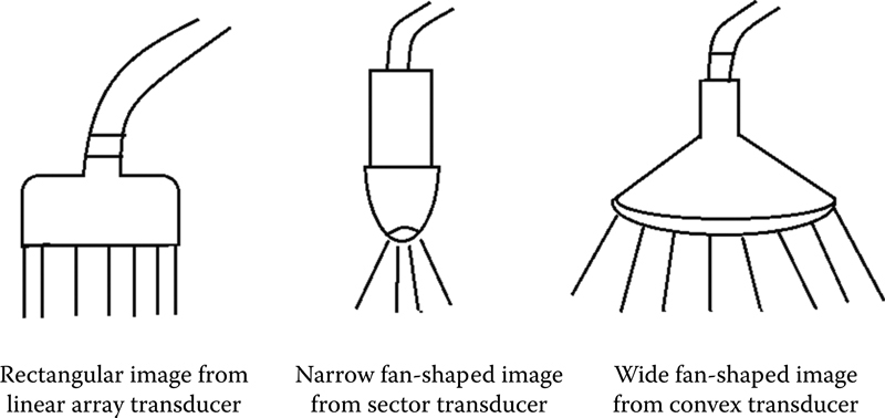
Figure 1.2 Illustrating various types of transducers.
Frequencies of 2–5 MHz are required for deeper structures in abdomen and pelvis, that is, >12–15 centimeters from the surface.
High frequency—better spatial resolution, greater attenuation, and poor penetration.
High frequencies →
• Broadens the bandwidth
• Reduces the quality factor (Q)
• Shortens the spatial pulse length (SPL)
1. Endovaginal probes for early obstetric and gynecologic problems.
2. Endorectal probes for prostate imaging.
3. Intraoperative/laparoscopic—it is used to insert through the laparoscopic port in the abdominal wall to enter into the abdominal cavity and retro peritoneum.
Real-time imaging systems are those that have frame rates fast enough to allow movement to be followed (>16 frame rates/second). For fast-moving structures such as heart, high frame rates are beneficial.
Types:
1. Mechanical scanners: Single-element transducer is mechanically moved to form images in real time. It is obsolete nowadays.
Oscillating transducer
Rotating wheel transducer
2. Electronic array: Transducers do not move but are activated electronically to cause ultrasound beam to sweep across the patient. It is most frequently used now.
Piezoelectric crystal element: Located near the face of a transducer.
Outside electrode: Grounded to protect the patient from shock. Its outer surface is coated with a water-tight electrical insulator.
Inside electrode: Abuts against a thick backing block; absorbs the sound waves transmitted back into the transducer.
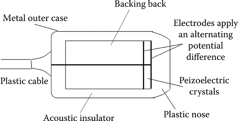
Figure 1.3 Illustrates construction of ultrasound transducer.
Backing block (Damping): Made of tungsten and rubber powder in epoxy resin.
• Absorbs the sound waves transmitted back into the transducer
• Shortens the pulse duration and pulse length (SPL)
• Increases axial resolution
• Widens the bandwidth and reduces the quality factor (Q)
Housing-strong plastic: Acoustic insulator of rubber/cork that prevents sound from passing into the housing (Figure 1.3).
Diagnostic transducers: Have damping material—wide bandwidth, low Q
Therapeutic transducers: Without backing material—narrow bandwidth
Piezoelectric effect (PE) crystal is the main component of a transducer (located near the transducer’s face).
Has the unique ability to respond to the action of an electric field by changing the shape (strain). Strain is the deformity of crystal (into different shapes) when voltage is applied to the crystal.
Have the property of generating electric potentials when compressed.
Naturally occurring PE materials—quartz, Rochelle salts, tourmaline.
Artificial PE materials—ferroelectrics—lead (Plumbium) zirconate titanate (PZT), barium lead titanate, lead metianobate, and polyvinylidene fluoride (PVDF).
Synthetic materials are good both at transmitting and receiving sound waves, whereas naturally occurring crystals are better at doing one or the other.
Related posts:
Stay updated, free articles. Join our Telegram channel

Full access? Get Clinical Tree


