David O. Cosgrove, Robert J. Eckersley, Christopher J. Harvey, Adrian Lim
Ultrasound
Ultrasound is an important technique for tomographic imaging of soft tissues. It provides images in real time and so can also be used to interrogate the movement of structures such as cardiac valves and biopsy needles and, using Doppler, the patterns of blood flow in both large and small vessels. Contrast agents in the form of microbubbles are invaluable in cardiology and the liver, but images are generally obtained without them and thus are not dependent on organ function. Elastography adds information on tissue stiffness, an extension of manual palpation. Ultrasound at diagnostic intensities does not cause damage to tissues and, although complete safety is difficult to prove, it can be used for ovarian follicles and in the developing fetus.
Despite its very wide application in obstetrics, cardiology, abdominal and small parts imaging, the parts of the body that can be imaged with ultrasound are limited because ultrasound does not cross tissue–gas or tissue–bone boundaries so that structures lying deeper to them are obscured. Thus, ultrasound is not generally useful for the lungs and is difficult to use in the head—except in the neonate, as the open fontanelles provide an excellent ‘window’. In other areas, overcoming the barrier caused by the bony skeleton and gassy viscera requires technical expertise. Ultrasound is also subject to many artefactual signals, which complicate interpretation and add to the operator skills required.
Patient acceptance is high and preparation is minimal: bladder filling is required for pelvic imaging and fasting is helpful for the gallbladder. Mobile imaging systems for theatre and emergency point-of-care use are widely available and are being miniaturised while retaining their quality, so that in the future they may become used by all medical practitioners, though training will have to be made available.
Ultrasound is the ideal technique for biopsy and interventional guidance because it operates in real time. Real-time ultrasound can be fused with previously acquired 3D CT or MR data sets to improve the precision of biopsies and tumour ablation. A position sensor then adjusts the CT or MR image to match the ultrasound slice, thus combining the strengths of each technique.
Nature of Ultrasound
Ultrasound is a coherent, mechanical vibration at high frequencies. In most diagnostic applications, frequencies in the 2–20 MHz (megahertz = million cycles per second) range are used, corresponding to wavelengths of 1–0.1 mm in tissue.
Ultrasonic Transducers
Ultrasound is generated by piezoelectric materials which have the property of changing thickness when a voltage is applied across them. Lead zirconate titanate (PZT) is the most widely used. The piezoelectric effect derives from movements of a heavy, charged atom that is loosely bound within a complex crystal; when an electrical field is applied, the atom moves and distorts the crystal. PZT is a ceramic that is cast as a thin plate that may be disc-shaped or more usually is formed into a strip that is then sliced into several hundred tiny elements as an array, with metal electrodes on the two surfaces. It is polarised by heating it above a critical temperature (the Curie point, which is around 200°C) and then allowing it to cool in an electric field, a process similar to that used to polarise a magnet. When electrically pulsed, the crystal rings like a bell at a resonant frequency which is mainly determined by its thickness. Higher-frequency crystals are thinner and thus more difficult to manufacture. The piezoelectric effect is symmetrical, so that the same or a similar crystal is used as the receiver to produce small electrical signals when struck by an ultrasound wave.
The crystal is mounted in a conveniently shaped holder which contains the electrodes and any associated electronics as well as the lenses and matching layers required to improve the beam shape and enable efficient transfer of acoustic energy between the crystal and the patient (see later). The whole assembly is known as the probe or transducer.
The development of single crystal piezoelectric materials is improving the sensitivity and the bandwidth of transducers because the piezo domains are more truly aligned than in a traditional amorphous ceramic material. Manufacture is similar to silicon chip technology, seeding a molten pot of the material in a crucible and slowly cooling it to allow crystallization. The material is then machined to the required shape (usually as a multi-element array).
Propagation in Tissue
Ultrasound travels through tissue as a beam, which, for most clinical applications, is focused to around 1 mm or less in diameter at the focal zone. It propagates as a sequence of compression and rarefaction waves which are transmitted by the elastic forces between adjacent tissue particles. The particles move in the same direction as the wave—thus ultrasound is a longitudinal wave unlike the transverse waves that occur at the surface of water where the particles move up and down as the wave travels horizontally. The frequency of the oscillations is inversely proportional to the wavelength ( f = c/λ, where f is frequency, c is the velocity of ultrasound and λ is the wavelength).
The way in which the ultrasound wave is transmitted varies with the strength of the elastic forces between adjacent particles (which relates to the elasticity of the tissue and thus to the velocity of ultrasound) and with the masses of the particles (which determines density). These two factors determine the acoustic impedance (Z) of the tissue (Z ≅ ρc, where ρ is density and c is the velocity of ultrasound). When the particles are heavy, a given amount of energy is transmitted with small movements of the particles; when they are light, larger excursions occur, though it should be understood that the actual distance a particle is moved at diagnostic ultrasound intensities is less than a nanometre. In clinical practice, since the velocity of ultrasound in tissue is almost constant (at 1540 m s−1), changes in impedance are mainly attributable to differences in density.
The constant speed of ultrasound in soft tissues allows the depth of reflectors to be calculated by measuring the delay in the return of echoes after the ultrasound pulse has been transmitted. This is the essence of the pulse-echo method used in both ultrasound imaging and most forms of Doppler ultrasound. (Note that the position of reflectors across the imaged plane is determined in a quite different manner, by the direction in which the ultrasound beam is transmitted; see below.)
Attenuation
Provided that the constituent particles of a tissue are small enough to move as a single entity, the acoustical vibrations are transmitted in an orderly and efficient manner. However, when very large molecules are involved, the vibrations become disorganised, one part of the molecule responding more or less than another. While coherent vibration is what we know as sound, chaotic vibration is heat. This loss of coherence, the most important cause of dissipation of ultrasound energy, is known as absorption and is approximately proportional to the concentration of large molecules which correlates fairly well with viscosity.
Absorption is also highly dependent on the ultrasound frequency, higher frequencies being more strongly absorbed. For average soft tissues the loss amounts to approximately 1 dB per cm tissue depth for each megahertz. Thus, when using a 3-MHz probe, for every 2 cm of tissue penetration there will be a loss of 6 dB, which is a halving of the pressure amplitude of the signal. The noise floor (produced by random vibrations in the tissue and the transducer as well as by imperfections in the electronics) lies some 60–90 dB below the peak signal so the penetration of such a probe would be limited to about 20 cm depth and to 10 cm for a 6-MHz probe.
Ultrasound energy is also lost to the receiving transducer when it is reflected or refracted away from the returning line of sight or if the beam diverges. The total loss from all these mechanisms is called attenuation.
High-frequency ultrasound gives better resolution because of the shorter wavelength, but the frequency dependence of attenuation in tissue is the limiting factor to the maximum that can be used in any given clinical application. Frequencies as high as 20 MHz can be used when only a few millimetres of tissue are to be traversed, such as for examining the eye and skin and for intravascular ultrasound (IVUS). For superficial tissues, such as the thyroid, breast and scrotum, 10–18 MHz is appropriate. For the heart, abdomen and second and third trimester obstetrics, 3–7 MHz is optimal, while for some difficult applications, such as the abdomen in obese subjects, and for transcranial studies (most of which use Doppler), one has to resort to 1.5- or 2.5-MHz transducers. This frequency limitation can be reduced by the use of longer-duration coded transmit pulses, which essentially impose a signature on the pulse (for example, by making the frequency increase during the pulse, so-called chirp encoding). This approach allows the spatial resolution to be maintained while using longer transmit pulses and improving the sensitivity of the system to weak echoes.
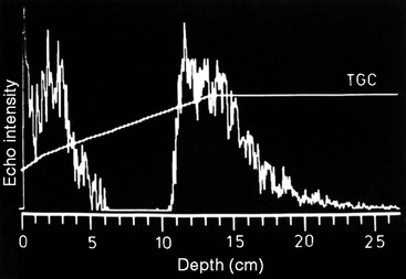
Obviously a way to compensate for this rapid reduction in signal intensity is required if the image is to display similar reflectors as equal in brightness over a range of tissue depths. This is achieved by applying progressively increasing amplification (gain) to later echoes in proportion to their depth using a time-varying amplifier that is triggered when each ultrasound pulse is sent. This is the TGC (time gain compensation), an important user control that must be set to equalise the image brightness for superficial and deep structures. Most imaging now incorporates automatic gain and TGC correction which makes it easier to set the imaging parameters correctly.
This trade-off between depth and resolution is the chief reason for the development of intracavitary probes which have the additional advantage of avoiding gas and bone barriers. Examples are transrectal probes for the prostate and transvaginal probes for gynaecology and first trimester obstetrics, as well as transoesophageal probes for echocardiography. These can operate at 7–15 MHz to give excellent spatial resolution and, since the barriers caused by impenetrable overlying structures are obviated, high-quality images are reliably achieved. Intracavitary probes can be combined with endoscopes for transoesophageal and transgastric ultrasound to evaluate the submucosal and deeper layers of the viscera that are not accessible to endoscopy and to provide high-resolution images of adjacent structures, such as regional lymph nodes, the pancreas, the lower bile duct, the gallbladder and parts of the liver.
Reflection
The other important mode of ultrasonic interaction with tissue is reflection. Some of the transmitted energy is reflected whenever the beam crosses an interface where the transmission properties change, the proportion depending on the degree of impedance mismatch (change of Z). The phenomenon is similar to that occurring in a rope that is fixed at one end and made to oscillate by shaking the free end up and down: provided the rope is of uniform construction, waves travel along it until they die out or reach the fixed end. But if a part of the rope is thicker or more rigid (or the reverse), then the waves are partly reflected back when they reach this ‘obstruction’. At the fixed end the same effect occurs but to a greater extent, all of the vibrational energy being returned as a full-strength ‘echo’ because this part of the rope cannot move at all.
Thus the intensity of the reflection depends on the degree of change in the rigidity or elasticity of the tissue (and potentially also of velocity, though this varies very little in soft tissues). Ultrasound that is not reflected passes through and is available for imaging deeper tissues. Only a small fraction (2–10%) is reflected at each soft- tissue interface but almost total reflection occurs at tissue–gas interfaces and some two-thirds of the incident ultrasound is reflected at a tissue–bone or tissue–calculus interface so that an acoustic ‘shadow’ is produced deep to these surfaces. They are essentially opaque to ultrasound, which therefore cannot be used to image aerated lung, nor generally where the tissue is covered by bone, for example, the brain.
Two main types of echoes are encountered clinically, depending on the structure of the reflecting surface (Table 3-1). Where this is smooth compared with the ultrasonic wavelength (i.e. the surface is flat over an extent of several millimetres) the reflected wave obeys Snell’s law for light and is reflected at an angle equal to the angle of incidence. By analogy these echoes are sometimes known as specular or mirror-like echoes. In the usual arrangement for ultrasound imaging, where the same transducer is used both for generation and reception of the ultrasound, only those smooth surfaces that lie close to right angles to the sound beam return these echoes. The directed reflection means that the echo is of high intensity: strength and directionality are the cardinal features of these echoes from flat surfaces. They arise from the linings of hollow viscera and blood vessels, from the valves of the heart, from organ capsules and fascial planes, from the skin and from gas and bone surfaces.
TABLE 3-1
Echo-Producing Mechanisms
| Specular: mirror-like reflections from flat surfaces | Strong, directional echoes |
| Scattered: interference patterns from small parenchymal discontinuities | Weak, non-directional echoes |
Where the irregularities in the surface are of the same order of size as the ultrasound wavelength itself, i.e. 0.01–1 mm, a different mechanism known as scattering produces echoes; here each small interface (e.g. a lobule of an organ, arterioles, venules, etc.) is vibrated by the mechanical shock it has received from the incident ultrasound pulse. The vibratory energy is re-radiated more-or-less equally in all directions, each discontinuity behaving as an isolated point source of ultrasound. Thus the echoes are isotropic and potentially detectable from any direction. However, because the energy is distributed across the surface of an expanding sphere, the signal received by the transducer from any single vibrating particle is weak and in practice is only detectable when several wavelets from adjacent particles happen to be superimposed and produce an additive effect. Low intensity and detectability from any angle are the cardinal features of these scattered echoes. They arise from soft-tissue parenchyma and thus are usually the more important diagnostically. It is important to note that the texture in the image is an interference pattern and is not a one-to-one representation of the histological reality. This is why tissues of very different structures (e.g. liver and spleen) can produce similar echo textures. Many soft tissue reflectors actually display properties that are intermediate between specular and scattered echoes.
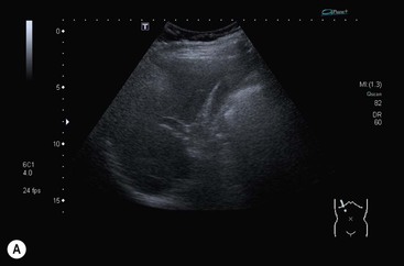
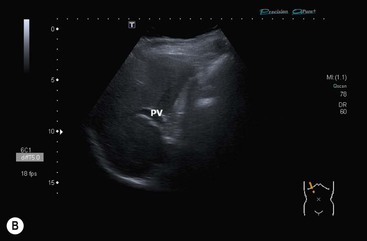
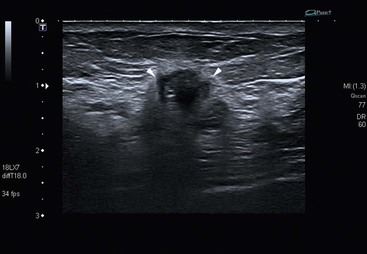
Ultrasound is generally considered to be conducted in a linear manner whereby the waveform of the pulse is preserved with depth. In fact, this is not quite true and non-linear propagation is an important phenomenon in which the sine wave shape of the original pulse emanating from the transducer becomes distorted so that it comes to contain higher-frequency components or harmonics. This occurs because the speed of sound conduction increases with increasing density of the conducting medium (tissue or biological fluids) so that the compression part of the cycle travels slightly faster than the rarefaction part and this distorts the wave much in the way that an ocean wave builds and breaks as it approaches the shore (though the mechanism is not identical). The development of these harmonics depends on the sound intensity: higher acoustic powers produce stronger harmonics and therefore they are weak in the parts of the sound beam away from the central, desired portion. They are also weak for the first few millimetres of tissue depth because they take a few cycles to build up. These facts have been exploited in ultrasound systems that use software to select for the harmonics in the returning echoes by transmitting at, say, 1.5 MHz, and tuning the receiver to 3 MHz to remove the fundamental echoes. In doing so, the beam aberrations from side lobes and from reverberations in the superficial tissue layers are suppressed (see under ‘Resolution’). The tissue harmonic image is cleaner with higher contrast and this has been especially useful in echocardiography and in abdominal imaging (Fig. 3-1).
Ultrasound Methods
The Pulse-Echo Method
In the conventional pulse-echo ultrasound imaging process, signals are displayed corresponding to the depth calculated from the time elapsed between transmission and receipt of the echoes, using the speed of sound; the same principle is used in radar and sonar.
In the simplest system, which is rarely used nowadays, only the depth of the echo-producing interface is determined. It is displayed as a vertical deflection on a monitor and is known as an A-scan (A for amplitude). It has one spatial dimension and the strength of the echoes is indicated by the height of the deflection (Fig. 3-2).
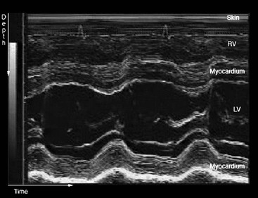
If the transmitted pulse is repeated rapidly, then the position and intensity of any interfaces that arise from moving structures change with time. A simple way to display these changes is to modulate the intensity of the spot on the monitor in proportion to the intensity of the echoes and then to sweep the line of echoes across the screen. The resultant trace, showing depth versus time, is known as an M-mode display (M for movement; sometimes also referred to as TM, for time-motion imaging) and is especially useful in echocardiography for evaluating the rapid movements of valve leaflets (Fig. 3-3).
A two-dimensional tomographic ultrasound image is formed by sweeping the beam through a slice of tissue and mapping the echogenicity of the reflectors as shades of grey to form a B-mode image (B for brightness), also known as a grey-scale imaging. This is the main mode used for ultrasound imaging. While the depth of the reflectors is determined by the delay in the return of the echoes to the transducer (the pulse-echo principle), their lateral position is determined by the direction in which the ultrasound beam was sent.
Beam Steering
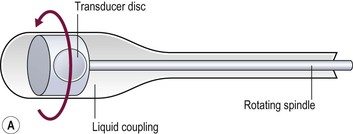
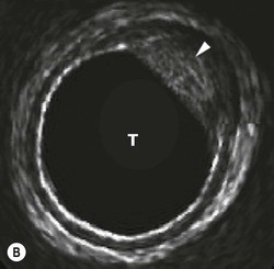
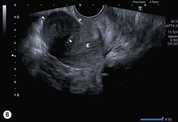
The direction in which the beam is sent can be determined mechanically or electronically. Mechanical steering systems were used widely but are now restricted to intracavitary techniques (endoscopic and intravascular). They use a simple, single element transducer which is mechanically swept through an arc, typically of 360°, by spinning it on a wheel (Fig. 3-4). The resulting image has a circular shape with the transducer itself at the centre and the tissues arranged around it with the intima closest to the transducer.
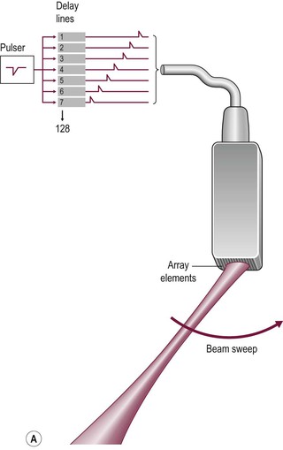
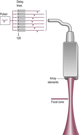
Electronic sector systems (also known as phased arrays) have replaced mechanical systems for most applications. Here the beam direction is controlled by building up interference patterns between the waves transmitted from an array of a large number of small transducer elements. The usual arrangement consists of numerous PZT elements (512 in state-of-the-art systems), each 1 mm or less in width and 5–10 mm in length, stacked up to form a strip. Each has separate electrical contacts and the pulses to each element are serially delayed from one end of the array to the other. These minute differences in timing occur within the short time needed to form an individual pulse and they produce interference patterns in which the troughs and peaks of the pressure waves add where they coincide and subtract where they are out of phase (hence the term ‘phased array’) (Fig. 3-5). This results in a beam that is directed to one side. For the next pulse, a slightly different set of delays is applied to adjust the steering. During receipt of the returning echoes the electrical signals from the individual elements are delayed before they are summed in the beam former, exploiting the same summing and cancelling approach; the aggregate signal produced is the electronic equivalent of mechanically angling the transducer face in the required direction. Though the concept is fairly easy to understand, the underlying mathematics is complex and generally requires dedicated hardware; however, software emulations have been developed so that beam forming can be performed in a PC, opening the way to cheaper and more flexible machines. The resulting image has a triangular or sector shape which has the important practical advantage of requiring only a small skin contact area (or footprint), although it provides only a limited display of the superficial tissues.
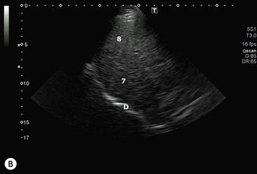
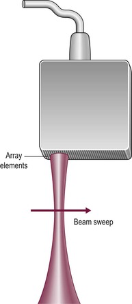
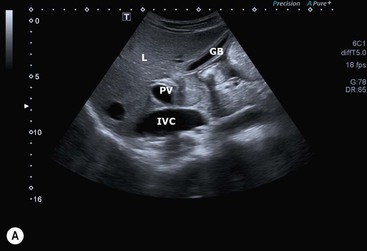
The operation of electronic linear array transducers is a little simpler. They are longer than phased arrays and the beam is moved across the imaged plane by firing the elements in groups, starting from one end of the array and stepping along to the other (Fig. 3-6). This produces an image with a rectangular shape, best suited for the superficial structures that are of prime interest in small parts imaging (Fig. 3-7). In a simple variant, the linear array is shaped as a curve so that the field of view is almost trapezoidal, as with sector imaging, but with a longer skin line. This compromise is particularly useful when both superficial and deeper structures need to be imaged, for example in obstetrics (Fig. 3-8).
Electronic arrays are more difficult to manufacture than mechanical probes and the dedicated electronics adds to their overall cost. However, they can be made very small and light and the flexibility and rapidity with which the beam can be steered are important advantages where complex functions, such as combined imaging and Doppler (duplex), are required.
An important limit to the rate at which ultrasound information can be acquired is set by the speed of sound in tissue (average in soft tissue 1540 m s−1). It is necessary to wait for the echoes from each pulse to have faded away before the next is transmitted, since if the second pulse is sent too early the last echoes from the first pulse overlap early echoes from the second and are falsely registered on the image as superficial structures. To avoid this range ambiguity artefact, the pulse repetition frequency (PRF) must allow a delay of at least the time taken for the most distant echoes to return or fade away. In practice, this limits the PRF to about 1000 pulses per second (lower for deep structures, higher for superficial). The choice of the way these pulses are distributed in time and space is determined by the priorities for each particular application. They may be spread apart and the imaging area restricted in order to maximise the frame rate, a solution that is appropriate for echocardiography. However, this results in a coarse image because of the low line density. The resulting sacrifice in spatial resolution and the small image size are not ideal for general applications where image quality is important. Here the low frame rate is generally less of a sacrifice, so a high line density and wider imaging area are the better trade-off.
Resolution
Ultrasound resolution must be considered separately for the two dimensions, along and across the beam. Depth or range resolution is determined by the length of the ultrasound pulse, which is kept as short as possible by placing a sound-absorbing backing block behind the piezo material and by shortening the driving pulse with damping circuitry. These result in an emitted pulse some two wavelengths long; this equates to a shorter physical pulse if higher frequencies can be used and this is the main reason for the improved resolution of high-frequency systems.
Lateral resolution, in contradistinction, depends on the width of the ultrasound beam. Two means of controlling this have been exploited: the use of large aperture transducers and the addition of mechanical or electronic lenses.
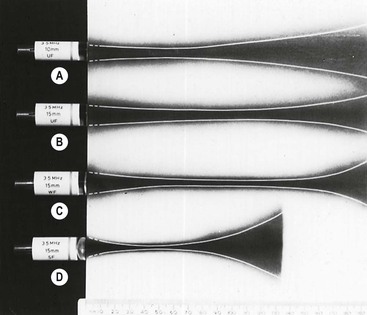
The ultrasound emitted from a point source spreads in a hemisphere but, as the source is enlarged, it forms a beam with near-parallel sides for a few centimetres of depth before the beam diverges again (Fig. 3-9). The changeover is the transition between the near (Fresnel) and far (Fraunhofer) zones. In fact it represents the point beyond which the ultrasound waves from the edge of the transducer arrive less than a wavelength later than those from the transducer centre so that larger aperture transducers have longer near fields. The beam is actually formed by the same interference effects that are exploited to steer the beam in electronic transducers and occur because the compression and rarefaction phases of the ultrasound pulse add in the direction of the beam but cancel elsewhere.
Adding a converging lens (usually a curved layer of plastic bonded to the front of the piezo material), or simply shaping the transducer face into a shallow dish, acts to narrow the beam (Fig. 3-9). This can be thought of as working in the same way as an optical lens, i.e. by beam refraction, but a more useful concept is based on the fact that the lens conducts ultrasound more rapidly than tissue, so that waves emanating from the transducer edge are fractionally ahead of those from the centre as they enter the tissue. Thus interference patterns are set up across the sound field that emphasise the centre region of the ultrasound beam and cancel ultrasound waves that otherwise would spread laterally.
The same effect can be produced with a multi-element array by sending the transmit pulses to the outer elements fractionally ahead of those to more central elements—this is the electronic equivalent of shaping the transducer surface into a dish (Fig. 3-10). Focusing also occurs on receipt of the echoes, in a reciprocal fashion. While electronic focusing is complex, it confers two benefits. First, the focal position can be altered by changing the delays within the transmit pulse so that the probe can be optimised for each clinical situation—with a mechanical probe the focus is fixed and so the entire probe must be exchanged if the focal zone needs to be altered. In addition, with electronic focusing on receipt of the echoes, the focus can be set close to the transducer initially (to optimise resolution of superficial tissues) and then progressively refocused deeper into the body to track the train of echoes returning from deeper interfaces. This dynamic focusing optimises resolution over the entire depth of the image.
Tight focusing of the ultrasound beam has the undesired effect of accentuating its divergence in the far field, so that the beam is only optimal over a short depth (Fig. 3-9D). While such a transducer would be appropriate for structures where only a narrow strip of tissue is of interest, e.g. the retina in the eye, generally a better compromise is to use weak focusing together with as large an aperture as can reasonably be maintained in contact with the skin.
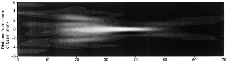
In practice, the ultrasound beam achieved is far from perfect (Fig. 3-11). Not only is the optimum beam width achieved over only a relatively short focal depth but also its profile, a bell-shaped curve across the beam, leads to smearing of signals from strong reflectors since they are detected from some distance off-axis (Fig. 3-12). In addition, the real beam has side lobes which are emitted at steep angles from the main beam so that unwanted echoes may be received from interfaces that lie a long way off-axis. These signals further smear the image, particularly when strong reflectors such as gas bubbles lie in their direction. These limitations also apply across the imaging plane, so that out-of-plane reflectors may also interfere. Minimising the loss of spatial and contrast resolution that results from these deficiencies is a major emphasis of the art and science of transducer design and is an area where marked progress continues to be made (see tissue harmonic imaging, above and Fig. 3-1).