Magnetic resonance angiography (MRA) of the brain obtained at 3 T imaging has made a significant clinical impact. MRA benefits from acquisition at higher magnetic field strength because of higher available signal-to-noise ratio and improved relative background suppression due to magnetic field strength–related T1 lengthening. Parallel imaging techniques are ideally suited for high-field MRA. Many of the developments that have made 3 T MRA of the brain successful can be regarded as enabling technologies that are essential for further development of 7 T MRA, which brings additional challenges.
- •
MRA obtained at 3 T is uniformly better than MRA obtained at 1.5 T, with major benefits including nearly double the SNR as well as magnetic field strength–related T1 lengthening, which improves relative background suppression.
- •
Parallel imaging techniques are ideally suited for high-field MRA, with advantages including faster acquisition, reduced motion artifacts, decreased blurring, less geometric distortion related to susceptibility effects, and increased spatial resolution.
- •
CE-MRA, and especially time-resolved CE-MRA, benefits substantially from acquisition at high magnetic field strength, with inherent competing requirements of both high spatial and temporal resolution.
- •
Acquisition of both unenhanced 3D-TOF and CE-MRA sequences during the same imaging session is frequently advantageous, with the diagnostic potential of the combination of techniques better than either alone, especially for evaluation of pathologic vascular entities such as AVMs, DAVFs, and coiled aneurysms.
Ischemic stroke and arterial occlusive disease
Aneurysm
Aneurysm screening/follow-up of untreated aneurysm
Aneurysm in the setting of acute subarachnoid hemorrhage
Treated (coiled) aneurysm
Giant/partially thrombosed aneurysm
Intracranial arterial dissection
Vascular malformations of the brain
Arteriovenous malformation
Capillary telangiectasia
Cavernous angioma
Developmental venous anomaly
Dural arteriovenous fistula
Vasculitis and vasospasm
Moyamoya
External carotid circulation pathology
| MR Imaging Scanner | Acquisition Time (min) | Matrix | Partitions, Thickness, Overlap | Repetition Time/Echo Time (millisecond) | Flip Angle | FOV (cm) | Bandwidth (kHz) | Imaging Options |
|---|---|---|---|---|---|---|---|---|
| 1.5 T | 11:28 | 256 × 224 1 NEX | 145 1.4 mm −0.7 mm | 36/6.9 Fr | 25° | 18 × 16.2 | 15.6 | VB, MT, Z512, Z2 3-slab MOTSA |
| 3 T, 2001 protocol, unaccelerated | 12:06 | 384 × 224 1 NEX | 145 1.4 mm −0.7 mm | 38/4 Fr | 25° | 18 × 16.2 | 15.6 | VB, MT, Z512, Z2 3-slab MOTSA |
| 3 T, unaccelerated | 6:08 | 384 × 224 1 NEX | 145 1.4 mm −0.7 mm | 38/4.2 Fr | 25° | 18 × 16.2 | 15.6 | ED, MT, Z512, Z2 3-slab MOTSA |
| 3 T, accelerated, sense = 2, 8 channel | 3:15 | 384 × 224 1 NEX | 145 1.4 mm −0.7 mm | 25/3.9 Fr | 25° | 18 × 16.2 | 15.6 | ED, MT, Z512, Z2 3-slab MOTSA |
| 3 T, accelerated, GRAPPA = 2, 12 channel | 4:24 | 384 × 235 2 NEX | 128 0.7 mm 0 mm | 21/3.69 | 25° | 18 × 16 | 40.5 | PFP SAT1 5-slab MOTSA |
| MR Imaging Scanner | Acquisition Time (min) | Matrix | Partitions, Thickness, Overlap | Repetition Time/Echo Time (millisecond) | Flip Angle | FOV (cm) | Bandwidth (kHz) | Imaging Options |
|---|---|---|---|---|---|---|---|---|
| 1.5 T | 00:53 | 256 × 224 1 NEX | 89 1.2 mm −0.6 mm | 6.6/2.4 | 45° | Axial 22 × 22 | 31.2 | ZIP 512 |
| 3 T | 00:53 | 416 × 224 1 NEX | 89 1.2 mm −0.6 mm | 6.7/2.06 | 40° | Axial 22 × 22 | 31.2 | ZIP 512 |
| MR Imaging Scanner | Acquisition Time (min) | Matrix | Partitions, Thickness | Repetition Time/Echo Time (millisecond) | Flip Angle | FOV (cm) | Bandwidth (kHz) | Imaging Options |
|---|---|---|---|---|---|---|---|---|
| 3 T | 02:40 | 320 × 320 1 NEX | 130 1.4 mm | 5.5/1.4 | 30° | Sagittal 25 × 25 | 62.5 | ZIP 512, ZIP × 2, VB, ED |
| Time-Resolved MRA Technique | Acquisition Time (min) | Matrix Orientation Partition/Thick Field of View | Repetition Time/Echo Time (millisecond) | Flip Angle | Frame Update (s) | Other |
|---|---|---|---|---|---|---|
| TWIST 3 T | 1:15 (0:07 for mask) | 192 × 192 Sagittal 120/1.4 mm 26 × 26 cm FOV | 3.15/1.27 | 25° | 2.2 (30 × 3D volumes) | 32 channel coil GRAPPA 6× (Acceleration in 2 directions) |
| TRICKS 3 T | 1:19 (0:09 for mask) | 192 × 192 Sagittal 110/2.6 mm 0.75NEX 28 × 22 cm FOV | 2.2/0.9 | 20 | 2.10 (36 × 3D volumes) | 8 channel coil Asset 2× (Acceleration in single direction) |
Principle clinical indications for intracranial MRA include evaluation of ischemic stroke, arterial occlusive disease, aneurysms, cerebral vascular malformations, dural arteriovenous fistula (DAVF), central nervous system vasculitis, vasospasm, and moyamoya.
MRA evaluation of ischemic stroke and arterial occlusive disease
Causes of ischemic stroke include vascular thrombosis, cerebral embolism, hypotension, and anoxia/hypoxia. Three-dimensional time-of-flight (3D-TOF) MRA is the technique most commonly used for routine angiographic evaluation of the intracranial circulation in patients with ischemic stroke (cerebral infarction). Three-dimensional TOF MRA provides excellent depiction of the circle of Willis and its proximal large branches. It readily depicts thrombotic vascular occlusion as well as stenosis related to arterial occlusive disease manifested by processes such as atherosclerosis and dissection. Three-dimensional TOF MRA is quite accurate for depicting widely patent normal vessels or demonstrating complete vascular occlusion, although very-slow-flow or susceptibility artifact can mimic an occlusion. Accurate assessment of partial stenosis is more precise at 3 T than 1.5 T, especially for small vessels. Additional signal-to-noise ratio (SNR) available from acquisition at higher magnetic field strength in conjunction with improved multicoil arrays allows for 3D-TOF MRA with higher spatial resolution, parallel acquisition techniques with inherent reduction in acquisition time, as well as motion artifact ( Fig. 1 ). Parallel imaging techniques gives rise to potentially confounding reconstruction artifacts ( Fig. 2 ). In-plane saturation effects that can result in a tapered appearance of vessels because of signal dropout due to slower-moving peripheral blood are less prominent at 3 T. The combination of conventional and low-dose postgadolinium 3D-TOF MRA has been advocated to provide more robust and specific evaluation of intracranial vascular stenosis.


Phase-contrast MRA (PC-MRA) techniques are not frequently used for evaluation of stroke, except if directional flow information or velocities are desired. The phase images of PC-MRA can be used to determine direction of collateral flow about the circle of Willis. PC-MRA is useful for performing MRA after administration of intravenous gadolinium because PC-MRA benefits from acquisition with presence of intravascular gadolinium, whereas 3D-TOF MRA is typically suboptimal following full-dose gadolinium administration because of confounding overlapping vascularity due to opacified venous structures.
For specific clinical indications, gadolinium contrast–enhanced MRA (CE-MRA), including time-resolved CE-MRA, can be helpful to assess intracranial vascular patency ( Fig. 3 ). High-resolution 3 T black blood MRA permits high-resolution vessel wall imaging useful for assessment of intracranial atherosclerosis.

MRA evaluation of aneurysm
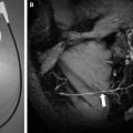
A common application of intracranial MRA is evaluation of arterial aneurysms, which can be categorized morphologically as either fusiform (10%) or saccular (90%). Saccular aneurysms most commonly arise from the circle of Willis (90%) and from the vertebrobasilar system (10%) and are believed to arise from flow-related vessel wall stresses and a complex combination of genetically inherited susceptibility. The incidence of sporadic intracranial aneurysms is 1% to 2% in autopsy series. There is an approximate 10% prevalence for familial intracranial aneurysms, which typically present in younger patients compared with those with sporadic aneurysms. Conditions predisposing aneurysm formation include autosomal dominant polycystic kidney disease, aortic coarctation, fibromuscular dysplasia, aberrant vascular anatomy (persistent trigeminal artery, arterial fenestration, azygous anterior cerebral artery), or connective tissue disorder (eg, Ehlers-Danlos). Aneurysms often develop on arterial feeders of an AVM; the causes of these are believed to be flow related. An additional 1% to 3% of aneurysms are related to trauma ( Fig. 4 ) and mycotic or oncotic etiology.
Specific subindications for MRA assessment of aneurysms include screening for aneurysms in asymptomatic high-risk populations, detection of aneurysms in the setting of acute subarachnoid hemorrhage (SAH), follow-up of known untreated aneurysms, follow-up of treated endovascularly coiled aneurysms, and evaluation of giant or partially thrombosed aneurysms. The optimal MRA technique used to evaluate aneurysms in these differing settings varies with the specific indication, as discussed later.
Ischemic stroke and arterial occlusive disease
3D-TOF MRA
Aneurysm
Aneurysm screening, follow-up of untreated aneurysm: 3D-TOF MRA
Aneurysm in setting of acute subarachnoid hemorrhage: CTA, DSA, 3D-TOF MRA (typically not first study, if obtained)
Treated (coiled) aneurysm: 3D-TOF MRA and intracranial CE-MRA
Giant/partially thrombosed aneurysm: 3D-TOF MRA, PC-MRA, CE-MRA
Intracranial arterial dissection
3D-TOF MRA, pregadolinium fat-suppressed T1 spin-echo, black blood MRA
Vascular malformations of the brain
Arteriovenous malformation: 3D-TOF MRA, a PC-MRA, CE-MRA, time-resolved CE-MRA
Capillary telangiectasia: GRE/SWI, postgadolinium T1 imaging b
Cavernous angioma: GRE/SWI, postgadolinium T1 imaging b
Developmental venous anomaly: CE-MRV, postgadolinium T1 imaging b
Dural arteriovenous fistula
3D-TOF MRA, a CE-MRA, time-resolved CE-MRA
Central nervous system vasculitis
3D-TOF MRA, conventional MR imaging (GRE/SWI, T2/FLAIR, pregadolinium + postgadolinium T1 imaging)
Vasospasm
3D-TOF MRA, CE-MRA, perfusion imaging
Moyamoya
3D-TOF MRA a , CE-MRA, time-resolved CE-MRA
External carotid circulation pathology
CE-MRA, time-resolved CE-MRA
Abbreviations: 3D-TOF, three-dimensional time of flight; CE-MRA, gadolinium contrast–enhanced magnetic resonance angiography; CTA, computed tomographic angiography; DSA, digital subtraction angiography; FLAIR, fluid attenuated inversion recovery; GRE, gradient echo; MRA, magnetic resonance angiography; MRV, magnetic resonance venography; PC-MRA, phase-contrast magnetic resonance angiography; SWI, susceptibility weighted imaging.
a Acquisition of both unenhanced 3D-TOF and CE-MRA sequences during the same imaging session is frequently advantageous, with the diagnostic potential of the combination of techniques better than either alone, especially for evaluation of pathologic vascular entities such as arteriovenous malformations, dural arteriovenous fistulas, and coiled aneurysms.
b Conventional postgadolinium T1-weighted imaging (eg, SE, GRE, MP-RAGE, and so forth).
MRA Screening and MRA Observation of Untreated Aneurysms
In the nonacute setting, 3D-TOF MRA is an excellent tool for following known aneurysms and screening for aneurysms in high-risk populations, such as for individuals with known autosomal dominant polycystic kidney disease or aortic coarctation. Superior depiction of aneurysms using 3D-TOF MRA at 3 T versus 1.5 T has been demonstrated. Using 3D-TOF MRA, aneurysms as small as 2 mm can be detected with a sensitivity of 74% to 98%. More recent literature has reported the possibility of detection of aneurysms as small as 1 mm ; however, to date, no large study examining the sensitivity and specificity for detection of aneurysms that small has been performed. Aneurysm size and location influence MRA sensitivity for detection of unruptured untreated aneurysms. Recently developed inversion recovery–based MRA techniques ( Fig. 5 ) and CE-MRA ( Fig. 6 ) are used less commonly than TOF techniques but are sensitive for detection of aneurysms.
Digital subtraction angiography (DSA) is generally a safe procedure but still has a small but nonzero risk of morbidity, including death. A prior large review has shown an overall neurologic morbidity rate of 1.3% and a permanent neurologic complication rate of 0.5%. Risk factors for DSA included advancing age (>55 years), preexisting cardiovascular disease, and longer duration of DSA procedure. For patients allergic to iodinated contrast material, DSA may be performed after pretreatment with steroids, such as in the Lasser protocol.
Aneurysms in the Setting of Acute SAH
The incidence of SAH is approximately 6 to 8 per 100,000 persons per year, with peak incidence occurring in the sixth decade of life. Most nontraumatic SAHs are the result of an intracranial aneurysm rupture.
MRA is typically not the first study in a patient with acute SAH. In the acute setting of SAH, conventional DSA remains the generally accepted gold standard for detection of intracranial aneurysms. Computed tomographic angiography (CTA) is currently playing an increasingly prominent role in the evaluation of acute SAH because it is convenient to perform CTA immediately after detection of an SAH on noncontrast head computed tomography (CT). CTA is usually immediately available, whereas magnetic resonance (MR) imaging often requires patient transfer to the MR imaging suite, which may not be near the emergency department. In addition, it is frequently necessary to summon on-call personnel necessary for MR imaging operation after routine hours. CTA has also proved quite accurate, with a reported success rate of 98% to 100% in detecting aneurysms in the setting of SAH.
There remains a role for MRA in the setting of negative DSA examination results because false-negative rates of up to 5% to 10% are reported with DSA. It is known that vasospasm, thrombosis of the aneurysm or of the parent vessel, compression of the aneurysm by adjacent blood or edema, small aneurysm size, and limited projections may obscure a ruptured aneurysm on DSA. In these situations, MRA has been shown to find aneurysms not identified on prior DSA.
MRA Evaluation of Treated (Coiled) Aneurysms
MRA is emerging as the technique of choice for long-term evaluation of residual or recurrent patency of aneurysms treated with endovascular coiling. Platinum alloy coils are designed to allow optimum visibility during endovascular treatments performed under fluoroscopic control. However, although this high attenuation is desirable during endovascular placement of the coils, the endovascular coil mass results in substantial beam hardening and streak artifact on subsequent CT and CTA examinations, degrading depiction of the aneurysm, adjacent vessels, and surrounding brain parenchyma. The susceptibility artifact arising from these platinum alloys is less at 3 T than 1.5 T predominately because of the ability to use smaller voxel sizes, usually resulting in only mild distortion of the local magnetic field and only slight loss of MRA signal intensity ( Fig. 7 ). Because of these factors, MRA is favored over CTA for follow-up of coiled aneurysms. Unlike platinum coils, metallic aneurysm clips usually demonstrate substantial magnetic susceptibility artifact that usually precludes adequate MRA assessment of residual/recurrent aneurysm for surgically treated aneurysms ( Fig. 8 ).
Evaluation of Giant Aneurysms and Partially Thrombosed Aneurysms
An aneurysm exceeding 2.5 cm in diameter is considered a giant aneurysm. These typically occur in the cavernous internal carotid arteries and middle cerebral artery (MCA) bifurcations. Giant aneurysms have a higher rate of rupture than smaller saccular aneurysms. Giant aneurysms are believed to enlarge from recurrent internal hemorrhage and characteristically have laminated mural hemorrhages of varying ages.
MRA evaluation of giant aneurysms is often not ideal with 3D-TOF MRA because of saturation effects on slow or recirculation internal flow ( Fig. 9 ). They are typically easily identified on standard imaging and can be visualized with other MRA techniques such as CE-MRA or PC-MRA. Although less marked at 3 T, slow and/or turbulent flow within the lumen of an aneurysm may lead to dramatic signal loss on conventional 3D-TOF MRA with associated reduction in detection with this technique. Also, a thrombosed aneurysm may be harder to characterize with TOF MRA because the thrombus can be isointense. Alternatively, subacute thrombus within the wall or periphery of the aneurysm can also result in a confounding bright T1 “shine-through” signal, resulting in misinterpretation of overall patency of the aneurysm lumen. Complete clinical evaluation of a TOF MRA should include direct review of the source images, as exclusive review of the maximum intensity projection (MIP) images alone is often diagnostically insufficient. CTA is also very useful for evaluation of giant aneurysms. Research applications of high-field PC-MRA include computational simulation of flow dynamics in a giant intracranial aneurysm.
MRA evaluation of aneurysm
A common application of intracranial MRA is evaluation of arterial aneurysms, which can be categorized morphologically as either fusiform (10%) or saccular (90%). Saccular aneurysms most commonly arise from the circle of Willis (90%) and from the vertebrobasilar system (10%) and are believed to arise from flow-related vessel wall stresses and a complex combination of genetically inherited susceptibility. The incidence of sporadic intracranial aneurysms is 1% to 2% in autopsy series. There is an approximate 10% prevalence for familial intracranial aneurysms, which typically present in younger patients compared with those with sporadic aneurysms. Conditions predisposing aneurysm formation include autosomal dominant polycystic kidney disease, aortic coarctation, fibromuscular dysplasia, aberrant vascular anatomy (persistent trigeminal artery, arterial fenestration, azygous anterior cerebral artery), or connective tissue disorder (eg, Ehlers-Danlos). Aneurysms often develop on arterial feeders of an AVM; the causes of these are believed to be flow related. An additional 1% to 3% of aneurysms are related to trauma ( Fig. 4 ) and mycotic or oncotic etiology.
Related posts:
 Stroke: High-Field Magnetic Resonance Imaging
Current State-of-the-Art 1.5 T and 3 T Extracranial Carotid Contrast-Enhanced Magnetic Resonance Angiography
Stroke: High-Field Magnetic Resonance Imaging
Current State-of-the-Art 1.5 T and 3 T Extracranial Carotid Contrast-Enhanced Magnetic Resonance Angiography
 Vascular Disorders: Insights from Arterial Spin Labeling
 Current Status and Future Perspectives of Magnetic Resonance High-Field Imaging: A Summary
 Pediatric High-Field Magnetic Resonance Imaging
 Ultrahigh-Field Magnetic Resonance Imaging: The Clinical Potential for Anatomy, Pathogenesis, Diagnosis and Treatment Planning in Neck and Spine Disease
Stay updated, free articles. Join our Telegram channel

Full access? Get Clinical Tree


