Wrist and Hand1
Joint Angles of the Distal Radius
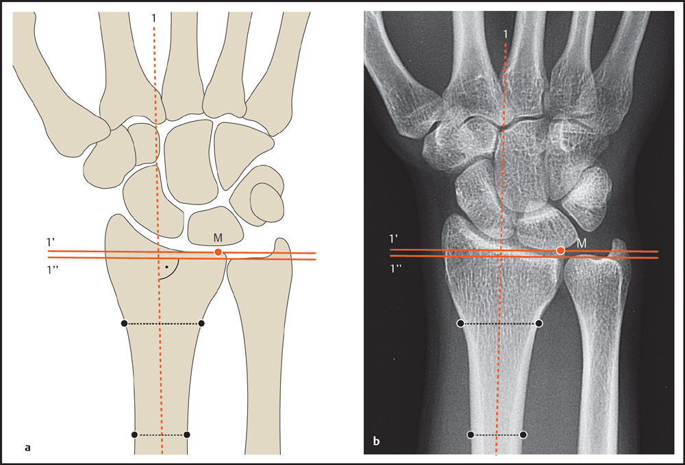
Radial Inclination
Radial inclination (synonyms: radial deviation, radial tilt, ulnar inclination, radial angle; Fig. 7.1 ) is measured on a dorsopalmar radiograph of the wrist in the neutral position. First the longitudinal axis of the radius is drawn as a reference line. The second reference line is drawn from the tip of the radial styloid process to the ulnar margin of the distal radius, passing through the midpoint between the dorsal and palmar radial cortical margins. Radial inclination is measured as the angle between the second reference line and a line perpendicular to the longitudinal axis of the radius.
Radial inclination
Normal value: 23° (15–35°)

1 Based on Schmitt R and Lanz U. Diagnostic Imaging of the Hand. Stuttgart: Thieme, 2007.
DiBenedetto MR, Lubbers LM, Ruff ME, Nappi JF, Coleman CR. Quantification of error in measurement of radial inclination angle and radiocarpal distance. J Hand Surg [Br] 1991;16A:399–400 Schmitt R, Prommersberger KJ. Karpale Morphometrie und Funktion. In: Bildgebende Diagnostik der Hand. 2nd ed. Stuttgart: Thieme; 2004: 122–130Palmar Tilt of the Distal Radius
The palmar tilt of the distal radius (synonyms: volar tilt, volar angle, dorsal tilt, dorsal angle, palmar slope, palmar inclination; Fig. 7.2 ) is evaluated on a lateral radiograph of the hand in the neutral position. The angle is measured between a reference line tangent to the dorsal and palmar margins of the distal radius and a line perpendicular to the longitudinal axis of the radius.
Palmar tilt
Normal value: 11° (0–20°)

Ulnar Variance according to Gelberman
Ulnar variance, also called the radioulnar index, is a measurement of the relative lengths of the radius and ulna determined on a dorsopalmar radiograph of the wrist. A neutral rotation view is necessary because pronation and supination movements of the forearm alter the relative length of the ulna, causing erroneous measurements in other joint positions.
An abnormal length of the ulna is associated with different pathologies of the wrist (Kienböck disease, negative ulnar variance; ulnolunate impaction syndrome and triangular fibrocartilage tears, positive ulnar variance). Furthermore, considering the ulnar variance is helpful in assessing the degree of posttraumatic instability of the distal radioulnar joint following distal radius fractures.
Various methods for determining ulnar variance have been described and evaluated. The Gelberman method described below is easy to perform. Steyers and Blair compared various techniques and found that, like the other methods evaluated, the Gelberman method yielded reliable results.
Gelberman defines ulnar variance as the distance between two lines perpendicular to the long axis of the radius ( Fig. 7.3 ). On the radial side, a line perpendicular to the radial axis is drawn through the ulnar margin of the radius. It should pass through the midpoint between the dorsal and palmar edges of the ulnar radial margin (see p. 108). On the ulnar side, a line perpendicular to the radial long axis is drawn tangent to the distal articular surface of the ulna.
Ulnar variance
• Normal value: | Length discrepancy ≤ 2 mm |
• Positive ulnar | Ulna longer than the radius variance: > 2 mm |
• Negative ulnar | Ulna shorter than the variance: radius > 2 mm |
Carpal Arcs of Gilula
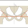
With a normal arrangement of the carpal bones, three smooth, parallel arcs can be traced along the proximal and distal rows of carpal bones depicted on a dorsopalmar radiograph of the wrist ( Fig. 7.4 ). The first arc follows the proximal contours of the proximal row of carpal bones. The second arc follows the distal contours of the same bones, and the third arc traces the proximal contours of the distal carpal bones (capitate and hamate).
Any break in the contour of a carpal arc is suggestive of carpal instability.
Carpal Angles
The wrist is evaluated for derangement of the carpal joints by determining the carpal angles on a lateral radiograph of the wrist. The carpal angles are formed by the longitudinal axes of the radius, lunate, scaphoid and capitate ( Fig. 7.5 ).
Two methods can be used to determine the longitudinal axes of the carpal bones: tangential and axial. In the tangential method, the longitudinal axes of the carpal bones are defined as follows ( Fig. 7.6a ). The scaphoid axis is found by drawing a line tangent to the palmar contour of the scaphoid, the capitate axis by drawing a line tangent to its dorsal contour. The lunate axis is found by drawing a line perpendicular to the line connecting the anterior and posterior horns of the lunate bone. In the axial method, the longitudinal axes of the carpal bones are defined as lines connecting the midpoints of the proximal and distal articular surfaces ( Fig. 7.6b ). The longitudinal axis of the distal radius is used in both methods. The angles listed in Table 7.1 are then evaluated to check for malalignment of the carpal bones.


Angle | Normal value (°) | Normal range (°) |
Radiolunate | 0 | – 15 to + 15 |
Radioscaphoid | 45 | 30–60 |
Scapholunate | 47 | 30–60 |
Capitolunate | 0 | – 15 to + 15 |
Carpal Height
Some types of wrist pathology are associated with decreased height of the proximal row of carpal bones. The following indices can be used to quantify this change:
Carpal Height Ratio of Youm
The carpal height ratio of Youm is found by dividing carpal height measured in line with the third metacarpal axis by the length of the third metacarpal ( Fig. 7.7 ).


Carpal height ratio of Youm
Normal value: 0.54 ± 0.03
Carpal Height Ratio of Natrass
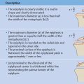
To calculate this ratio, the carpal height (a) is divided by the capitate length (b) ( Fig. 7.8 ). The axis of the third metacarpal shaft is defined first, and the carpal height is measured in line with that axis as the distance from the base of the third metacarpal to the distal radial articular surface. Capitate length is defined as the greatest distance between its distal and proximal articular surfaces.
Carpal height ratio of Natrass
Normal value: a/b = 1.57 ± 0.05
Related posts:

Stay updated, free articles. Join our Telegram channel

Full access? Get Clinical Tree


