16 On the Horizon: Ultra-High-Field MR
16.1 Introduction
Ultra-high-field (UHF) magnetic resonance imaging (MRI) appeared on the horizon in the late 1980s when the first 4T systems were installed in the United States at the University of Alabama, Birmingham; at the National Institutes of Health, Bethesda, Maryland; and at the Center for Magnetic Resonance Research of the University of Minnesota, Minneapolis.1 These early systems had multiple engineering challenges, and many technological developments were necessary before diagnostic quality MRI scans could be obtained.2 For more than a decade these high-field systems were mainly used in research, but there was always interest in exploiting the gain in signal-to-noise ratio (SNR) from UHF MRI for clinical applications. In 1998 the first human 8 T MRI system was installed at The Ohio State University, Columbus, which was then followed by a 7 T system at the University of Minnesota.3 These two UHF systems were still investigational devices, built in part from in-house components. The 7 T system’s 90-cm bore size was superior to the 8 T magnet’s 80-cm bore size in terms of patient comfort and gradient performance.4 The same bore-size advantage existed for 3 T systems compared to 4 T systems, and therefore the subsequent commercial MRI systems were built at 3 T and 7 T.5 The current era of UHF MRI began when three leading manufacturers of clinical MR systems, Siemens Healthcare, Philips Healthcare, and General Electric Healthcare, introduced their first commercial 7 T systems. The commercial availability of 7 T from these established vendors led to a new momentum for UHF MRI. More than 50 7 T MRI systems have been installed and are operational worldwide today. The development of self-shielded 7 T magnets has significantly reduced the costs of siting UHF MRI systems in hospital environments and will enable 7 T MRI to eventually integrate into clinical workflows. The first results have demonstrated the advantages of UHF, especially in neuroradiological applications, including increased SNR,6 improved sensitivity for functional brain imaging,7 and increased spectral resolution for magnetic resonance spectroscopy (MRS).8
16.2 Challenges of Ultra-High-Field MRI
Promising results of the first 7 T MRI studies, however, elucidated some of the new challenges associated with UHF MRI technology. At higher field strengths variations of the static magnetic field, B0, degrade image quality, especially in systems with larger bore sizes.9 Especially fast gradient sequences are sensitive to the central field nonuniformities due to accumulation of phase errors during the scan. For example, the ultrafast echoplanar imaging (EPI) MRI pulse sequence uses long readout and data sampling durations resulting in enhanced distortion artifacts at UHF.10 EPI is an essential sequence for functional magnetic resonance imaging (fMRI) and diffusion-weighted imaging (DWI). These imaging techniques are widely used in assessing brain function; therefore, solutions to B0 nonuniformity at UHF were critically needed for neuroimaging applications. Technology was developed that improved B0 field inhomogeneities by at least an order of magnitude through the introduction of additional subsidiary windings known as active shims.11,12
At UHF not only the static magnetic field B0 shows variations but also the radiofrequency (RF) field B1.13 The Larmor frequency of protons
is 300 MHz at 7 T, and the wavelength in tissue is thus shortened to around 14 cm. As a consequence, alternating B1 RF fields show considerable variations across the field of view and lead to variations in SNR and contrast across the image.14 Therefore, considerable resources were invested in the development of RF coils to improve both sensitivity and homogeneity. A novel technique called B1-shimming, or RF-shimming, has demonstrated promising results and might become the method of choice to improve the homogeneity of the RF field at UHF. Another promising solution to B1-inhomogeneities at UHF is the concept of traveling wave MRI. Traveling wave MRI radically changes the design of the RF technology. The bore of the magnet is used as a wave guide coupled to an antenna that is positioned at the end of the bore or as a small dipole close to the patient within the bore of the magnet. The bore of the magnet acts like a high-pass filter for traveling waves. For a typical 60 cm bore size of a 7 T magnet the cutoff frequency for the high-pass filter is very close to 298 MHz, corresponding to the hydrogen Larmor frequency at 7 T. The high dielectric constant of the human body diffracts the energy of the RF field at the surface of the body, and consequently the energy flows into the body. The entire bore of the magnet acts essentially as a very long RF coil.15
The higher static magnetic field B0 at UHF creates a longer magnetization vector in tissue. The increased magnitude of the magnetization vector requires more energy deposition of the RF field B1 and leads subsequently to an increased specific absorption rate (SAR) and additional patient safety concerns at UHF.16,17 An increased static magnetic field B0 also leads to an increase of the spin-lattice relaxation time T1 and to a decrease of the spin-spin relaxation time T2 caused by spin diffusion and exchange. These relaxation time changes lead to modified contrasts at UHF and need to be considered in sequence design and parameter selection.18
Inside the MRI bore there are three gradient coils (Gx, Gy, Gz) that vary the static magnetic field B0 depending on the position. The gradient coils are built with wound wires or etched copper plates on fiberglass and are embedded in epoxy resin.19 Switching currents in the gradients coils are used for spatial excitation and encoding of the spins. The gradients in MRI scanners are defined by the gradient strength, the gradient rise time, and the region of uniformity.20 Lorentz forces on the current-carrying wires within the high static magnetic field B0 of the main magnet cause vibrations at audible frequencies. The acoustic noises from the gradient coils can potentially damage the patient’s hearing unless precautions are taken, such as earplugs or noise-reducing headphones. Therefore, multiple methods have been considered to reduce the acoustic noise and vibrations generated by the gradient coils, especially at UHG strengths, for example, by placing the gradients on rubber supports or vacuum-sealed gradient coil assemblies mounted directly on the floor so that they are mechanically decoupled from the magnet.21 At UHF strengths fast gradient echo sequences are frequently used to profit from the high static field strength. These sequences require quick gradient rise times and rapidly switching gradients, which can induce noticeable vibration artifacts in the images. The electric fields generated by the gradients can also cause peripheral nerve stimulations and tingling sensations in patients.22,23,24
Safety studies on the first 8 T MRI system in Columbus, Ohio, led the U.S. Food and Drug Administration (FDA) to classify MRI up to 8 T as a nonsignificant risk.25,26 This does not apply to patients with metallic implants. During an MRI examination, a metallic implant may interact with the static field B0, RF field B1, or gradient fields, and lead to translational or rotational motion, heating, device malfunction, or a combination of these effects.27 These effects have been studied for many clinically relevant implants at 1.5 T and 3 T, resulting in metallic implants with FDA-approved labeling for MRI procedures that are acceptable if specific conditions are met. At field strengths above 3 T only a few systematic MRI safety assessments of metallic implants have been performed; therefore, patients with metallic implants are excluded from participating in UHF MRI studies in most institutions at the moment.28 Therefore, new UHF MRI testing procedures for implants need to be designed and implemented. Despite all challenges, several human MRI systems with even higher field strengths, such as 9.4 T, 11.7 T, and even 14 T are either in planning or already operational.29,30
16.3 Potential of Ultra-High-Field MRI
16.3.1 Higher Signal-to-Noise Ratio
The impetus for UHF MRI is primarily the improvement in SNR afforded by higher main magnetic field strengths. SNR increases approximately linearly with the magnetic field strength.14,31
An increased SNR in MRI can be used to do the follows:
Achieve higher spatial resolution (i.e., smaller voxel sizes)
Shorten the often long measurement times in clinical MRI
Open possibilities for MRI and MRS for nuclei that are less abundant than the hydrogen nucleus (e.g., 13C, 17O, 19F, 23Na, 31P, 35Cl, 39K) to provide important physiological information about pathological changes or drug distribution noninvasively32,33
Improve the detection of low-concentration metabolites in proton magnetic resonance spectroscopy34
These important advantages of a higher SNR offer great potential for improved neuro-oncological MRI. Smaller voxel sizes may lead to improved detection of small cancerous lesions and metastases. Faster scan times shorten imaging sequences and protocols, thus reducing motion artifacts from restless patients.35
The high SNR of UHF MRI can also be exploited to compensate for inherent SNR losses of parallel imaging techniques (e.g., sensitivity encoding [SENSE], simultaneous acquisition of spatial harmonics [SMASH], partially parallel imaging with localized sensitivities [PILS[, generalized autocalibrating partially parallel acquisitions [GRAPPA]). These parallel imaging techniques are widely used to accelerate MRI acquisition by using phased-array coils that increase imaging speed without the need to have faster gradient switching.36
16.3.2 Enhanced-Contrast Mechanisms
UHF MRI offers advantages to enhance contrast mechanisms in neuro-oncology in several MR imaging techniques.
Susceptibility- or T2*-Weighted MRI
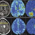
Susceptibility increases linearly with field strength B0. Magnetic susceptibility is a dimensionless quantity and describes how a bulk material is magnetized when exposed to an external field. Magnetic susceptibility also describes the distortion of a magnetic field caused by the spatial variations of magnetic susceptibility in biological tissue.37 Magnetic susceptibility is directly related to T2* relaxation time. Functional and physiological brain processes, as well as pathological alterations that change blood oxygenation in the brain, can be better assessed by T2* contrast imaging at UHF. Deoxygenated blood in the brain vasculature functions as an endogenous contrast agent and has been shown to better display tumor microvasculature with UHF MRI.38,39
Blood Oxygenation Level Dependent
Oxygenation sensitive imaging techniques, such as blood oxygenation level dependent (BOLD), profit as well from increased susceptibility contrast at UHF.40 The oxygen-transporting protein hemoglobin changes from the diamagnetic oxyhemoglobin to the paramagnetic deoxyhemoglobin when it unloads oxygen in tissue. Deoxyhemoglobin can therefore serve as an intrinsic paramagnetic contrast agent. The oxygen consumption of activated brain areas increases and leads to a vasodilatation and consequently to an increased blood flow and blood volume. The increased arterial blood flow is not matched by the local oxygen consumption; therefore, an excess of oxygen is present in the draining veins, and an increased concentration of the diamagnetic oxyhemoglobin is found. Under brain activation the T2* decay due to signal dephasing is therefore reduced in the vicinity of the vein, which leads to an increased signal. In functional MRI (fMRI) the enhanced signal changes can be used to better map activated brain areas due to the increase in image contrast.41 fMRI can be used to localize functional brain areas and spare brain structures with essential function during therapy.42 BOLD contrast can also be used to measure oxygen extraction fraction with the quantitative BOLD (qBOLD) technique.43
Contrast-Enhanced MR Angiography
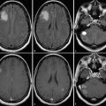
UHF contrast-enhanced MR angiography (MRA) provides the possibility of higher-resolution images with improved differentiation between tissue and enhancing vessels. UHF MRA also shows an increased sensitivity for subtle alterations of the blood–brain barrier with minimal contrast uptake. Tumor recurrence can potentially be detected at an earlier time point, allowing for an earlier adaption of the therapy. The increased sensitivity to contrast enhancement as well as the high-spatial resolution of UHF MRI may also improve the detection of small metastases44 and better differentiate these lesions from normal brain structures. Higher resolution also improves the detection of metastases in the vicinity of other enhancing structures, such as meninges, falx, and veins. An increased conspicuity of these lesions can influence treatment when solitary metastasis or multiple metastases are questioned. Higher field strengths may also be used to better visualize the arterial vasculature in tumors, which might provide additional information about neoangiogenic vessels.45
Perfusion MRI
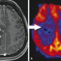
Perfusion MRI describes techniques that use endogenous or exogenous tracers to evaluate the perfusion of blood in the cerebral capillaries. In neuro-oncological imaging, perfusion MRI is used to differentiate active tumor areas from surrounding healthy tissue and from necrotic tumor areas. Perfusion MRI can be used for tumor staging and evaluation of tumor response because it can visualize neoangiogenesis in tumors, especially at UHF.46
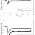
The perfusion technique dynamic contrast enhanced (DCE) MRI uses contrast agents to shorten the relaxation times T1 and T2 to create a contrast change during the passage of a contrast agent bolus. T1-weighted techniques show a signal increase with contrast agent concentration, whereas T2– or T2*-weighted techniques show a signal decrease. Contrast changes in the T1-weighted technique DCE MRI provide transfer constants, such as ktrans (volume transfer constant between blood plasma and extravascular extracellular space [EES]), kep (rate constant between plasma and EES), and Ve (volume of the EES per unit volume of tissue), and help to assess tumor angiogenesis.47 The first in vivo DCE MRI studies showed the potential of this perfusion technique at UHF.48
Contrast changes in T2*-weighted perfusion imaging are proportional to the concentration of contrast agent and therefore directly related to the relative cerebral blood volume (rCBV). Hemodynamic maps including mean transit time (MTT), time to peak (TTP), time of arrival, negative integral, and index can also be calculated in T2*-weighted perfusion imaging. At higher field strengths, lower contrast agent concentrations can be used to create the same T2*, contrast due to enhanced susceptibility contrast at UHF.49
The perfusion technique arterial spin labeling (ASL) uses blood as an endogenous tracer. In ASL the longitudinal magnetization of arterial blood proximal to the tissue of interest is changed (tagged), and then monitored during the passage to the tissue of interest. ASL at UHF strengths profits from an increased SNR as well as longer T1 values of the blood. Increasing T1 values of blood at higher field strengths contribute to a long-lasting ASL contrast to better delineate the passage of the arterial bolus through the capillaries. Nevertheless, UHF B1-inhomogeneities can lead to a decreased efficiency of the inversion of the arterial bolus. These limitations can be partly compensated with adiabatic inversion pulses, but these pulses come with the expense of increased specific absorption rate (SAR).50
Related posts:
Stay updated, free articles. Join our Telegram channel

Full access? Get Clinical Tree


