16 The Mitral Valve
Introduction
Over the last two decades, echocardiography (two- and three-dimensional [2D and 3D] transthoracic [TTE] and transesophageal [TEE]), computed tomography (CT), and cardiac magnetic resonance (CMR), have become crucial in the modern diagnostic workflow and management of patients with cardiovascular disease. Each of these techniques has advantages and limitations. CT has been commonly used for evaluation of the integrity of the epicardial coronary arteries and CMR is primarily used to address the pathologies of the myocardium. Echocardiography has been the first-line imaging technique for evaluating morphology, size, and function of heart valves. However, CT and CMR can also provide added information in regard to the morphology and function of the cardiac valves. Furthermore, each of these studies can also explore surrounding structures not affected by the disease with an unprecedented quality and detail. In this chapter, we describe and illustrate the anatomy and variants of the mitral valve (MV) apparatus “revisited” by these techniques. To illustrate various anatomical aspects of MV, we use the imaging technique that best fits the described component/s. For instance, all three imaging techniques may visualize papillary muscles (PMs) but CT is the technique which best shows the anatomical details of the PMs. We also briefly describe common mitral pathologies.
Mitral Valve Apparatus
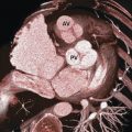
In 1972, Perloff and Roberts 1 first described the MV as a complex apparatus, which requires for maintaining a perfect competence, morphological integrity combined with a precise spatial and temporal coordination of the annulus, leaflets, chordae tendineae, and PMs (Fig. 16‑1). Any anatomical change or disruption of one or more of these components inevitably leads to mitral regurgitation.
Mitral Annulus
Anatomical books describe the MV annulus as an interrupted fibrous ring, divided into anterior and posterior segments, which encircles the atrioventricular junction and support the mitral leaflets. Later Angelini et al 2 demonstrated that a continuous fibrous ring separating the atrial and ventricular myocardium is rather rare. Instead, the posterior segment of the annulus is often seen as a discontinuous fibrous arc interrupted by variable amount of atrial and ventricular myocardial fibers while the anterior segment is in fact a sheet-like structure made of dense connective tissue that connects the anterior mitral leaflet with the aortic interleaflet triangle. This area is called mitral–aortic fibrous continuity, also known as mitral–aortic curtain or intervalvular fibrosa (Fig. 16‑2).
Two nodules of dense fibrous tissue namely the “right and left fibrous trigons” near the commissures exist to reinforce the base of anterior leaflet. Finally, from a surgical point of view, the MV annulus is defined as the hinge line of attachment of mitral leaflets on the atrial and ventricular myocardium.
The MV annulus has a 3D saddle-shaped configuration with the highest points corresponding to the midpoints of aortic attachment of the mitral–aortic curtain and the lowest at the fibrous trigones. 3 This configuration concentrates the peak stress on the two fibrous trigons. 4 , 5
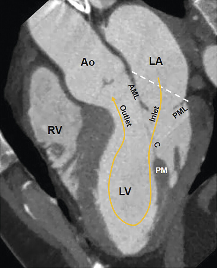
Absence of a rigid fibrous ring makes the mitral annulus a deformable structure that changes in dimension and shape during the cardiac cycle. During early systole, the normal annulus contracts and its saddle-shaped configuration becomes more pronounced. These systolic changes are mainly due to the anteroposterior shortening while the bicommissural diameter remains unchanged (Fig. 16‑3).
Longitudinal shortening of the left ventricle with each contraction drags the MV annulus toward the apex. The resulting increase in the left atrial diameters facilitates its filling by increased systolic forward flow from the pulmonary veins. The opposite changes occur in diastole (Fig. 16‑4).
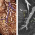
Finally, the posterior mitral annulus is close to important structures, including the left circumflex artery, the right coronary artery, the coronary sinus, and the bundle of His (posteromedially near the right fibrous trigone). The anatomical relationship of these structures with the hinge line of posterior annulus is important since the surgical suture during MV replacement occurs along the posterior hinge line and these vessels may be damaged (Fig. 16‑5).


Mitral Leaflets
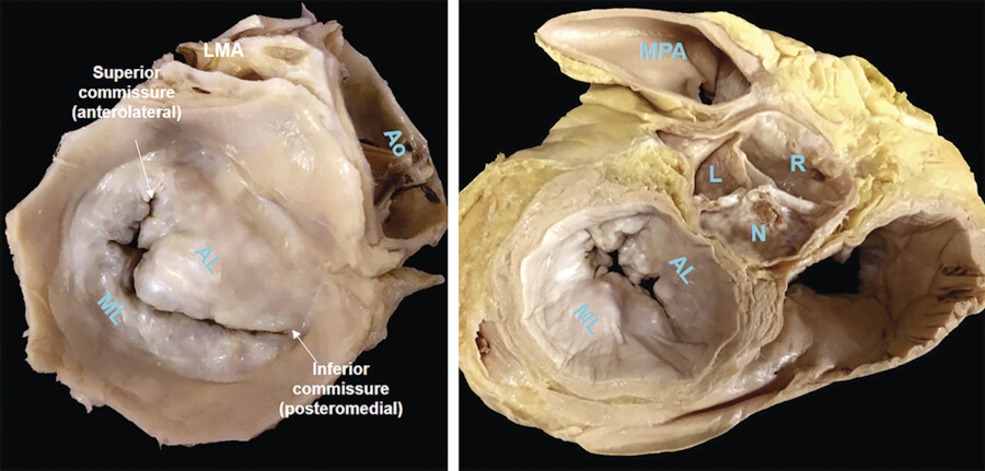
Two deep incisures called commissures are seen between the anterior and posterior leaflets. 6 The anterior leaflet has a triangular shape and covers approximately one-third of the entire annular circumference while the posterior leaflet has quadrangular shape and covers the remaining two-thirds. In most normal MVs, two additional incisures divide the posterior leaflet into three small segments or scallops (Fig. 16‑6 , Fig. 16‑7). To facilitate valve analysis (i.e., in the presence of mitral prolapse/flail) cardiac surgeons name the lateral scallop P1, the central scallop P2, and the medial scallop P3. Usually, the central scallop is the largest. Even though the free edge of the anterior leaflet has no identifiable incisures, the free margin of the anterior leaflet across the P1, P2, and P3 segments are named A1, A2, and A3, respectively. Occasionally, additional scallops occupy the commissural areas. These small scallops are called commissural scallops 7 (Fig. 16‑7).
From a ventricular perspective, both leaflets present two distinct zones: the rough zone and the clear zone (Fig. 16‑8). The rough zone covers the distal surface of both leaflets and receives the insertions of chordae tendineae assuming a corrugate surface. The clear zone covers the remaining ventricular surface and has a smooth appearance. From an atrial perspective, the rough zones correspond to the so-called coaptation surface, the area where leaflets juxtapose each other during systole. The width of this coaptation surface measures 8 to 10 mm. The redundancy of the coaptation surface provides a comfortable “valvular reserve” that assures an effective coaptation in presence of a certain degree of annulus dilation or leaflet tethering. Moreover, as the ventricular pressure rises, the leaflets mutually support each other along this zone. Since the vast majority of chordae insert within the coaptation surface, they may share the mechanical stress upon the leaflets (Fig. 16‑9).


Chordae Tendineae
The chordae tendineae (tendinous chords) connect the PMs and the ventricular wall to MV leaflets. They arise from the tip of PMs or the ventricular wall and split in numerous branches interconnected to each other in a complex mesh that ensures balanced distribution of mechanical forces. 6 The chordae inserting on the lateral half of both leaflets arise from the anterolateral PM, while the chordae inserting on the medial half originate from the posteromedial PM. One classification divides the chordae into first, second, and third order based on their insertion point on the leaflets. The first-order chordae or marginal chordae are stiff and less extensible cord inserting on the free edges of leaflets (Fig. 16‑10 , Fig. 16‑11 , Fig. 16‑12). Commissural chordae and cleft chordae are subcategories of first-order chordae. Rupture of these chordae almost always causes leaflet prolapse and mitral regurgitation. The second-order chordate are larger, elastic, and fewer in number that insert on the ventricular surface of the anterior leaflet at the confine between the rough and clear zones and often include two “strut chordate.” Their function is to prevent the leaflets from eversion. Furthermore, with reducing the motion at the peripheral part of anterior leaflet, the strut cords help the central part of the anterior leaflet to remain mobile. Thus, in systole the anterior leaflet takes a concave shape toward the outflow tract, while in diastole it bulges toward the inflow tract. This configuration facilitates blood outflow into the aorta during systole or blood inflow into left ventricle during diastole. Moreover, strut cords provide a fibrous continuity between the leaflet and the ventricular wall, supporting the contraction of longitudinal fibers of left ventricle and maintain left ventricular geometry. 8 Second-order chordal transposition has been used to correct anterior MV leaflet prolapse. 9 The third-order chordae or basal chordae originate directly from the ventricular wall and insert only on the posterior leaflet. These chordae limit the motion of the posterior leaflet (Fig. 16‑10 ).


Related posts:

Stay updated, free articles. Join our Telegram channel

Full access? Get Clinical Tree


