17 Trauma of the Distal Forearm
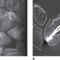
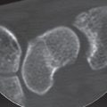
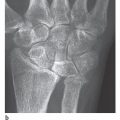
Basic diagnostic imaging of fractures and dislocations of the forearm near the wrist-whether acute or old, healed, malunited-healed, or not healed at all-consists of standard radiographs of the wrist in two planes, with a laterally placed cassette if necessary. CT imaging is becoming increasingly important to exclude occult fractures and to assess the congruence of the radiocarpal and distal radioulnar joints. It provides the foundation for planning surgical management of acute, complicated extra-articular and especially intra-articular fractures, for which three-dimensional (3D) reconstructions are useful. Dislocations and subluxations of the distal radioulnar joint and rotary deformities of malunited-healed radius fractures require clarification with CT of both wrists.
Acute Fractures and Dislocation Fractures of the Distal Forearm
Pathoanatomy and Clinical Symptoms
Fractures of the distal radius are among the most common injuries sustained, accounting for upwards of onesixth of all fractures seen and treated in the emergency room. The epidemiological understanding of fractures of the distal radius is based primarily on Scandinavian studies, which have revealed that distal radius fractures are more common in women than in men, with an incidence increasing rapidly after menopause and reaching a maximum between 60 and 69 years. The mechanism of injury is usually a fall from standing height rather than a highenergy mechanism. These factors all support a strong association of radius fractures with osteoporosis. Indeed, lowbone mineral density is found in most elderlywomen with a distal radius fracture, and osteoporosis is diagnosed in more than 50%. It has been suggested that the decrease in fractures of the distal radius after age 69 reflects increasing frailty resulting in an inability to extend the upper limb in protection, with the result that distal radius fractures are less common and hip fractures are more common. Thus, the isolated fracture of the distal radius typically occurs in the relatively fit osteoporotic individual, whereas fractures of the distal end of the radius associated with ipsilateral limb trauma are found with increasing frequency in young, active adults, due in part to a higher incidence of high-energy trauma or participation in sports and similar activities.
Classification
There are few areas of skeletal trauma in which eponymic descriptions are so commonly used as with fractures of the distal radius ( Table 17.1 , Fig. 17.1 ). Despite the fact that the observations of Colles, Barton, Smith, Pouteau, and Goyrand—to name just a few—were made solely from postmortem specimens, their descriptions of fracture morphology have served as guidelines for surgeons for more than 150 years and still provide a comfortable base for communication among clinicians. However, a classification system is necessary for effective description of the individual characteristics of specific fractures. Any fracture classification must consider the severity of the bone lesion and serve as a basis for treatment and evaluation of the outcome. It must have a high degree of inter-observer and intra-observer reliability. A fracture classification should help the surgeon to choose an appropriate method of treatment for any given fracture and should allow estimation of the outcome of treatment. We have found the classification system of Fernandez extremely helpful in decision making in our clinical practice and the AO/ASIF Comprehensive Classification of Fractures useful in preparing scientific papers.

The Fernandez Classification
In this classification, distal radius fractures are divided into five major types (Fig. 17.2a):
Type I fractures are bending fractures of the metaphysis in which one cortex fails because of tension stress, and the opposite cortex shows a certain degree of comminution.
Type II fractures are shearing fractures of the joint surface.
Type III fractures are compression fractures of the joint surface with impaction of the subchondral and metaphyseal trabecular bone.
Type IV fractures are avulsion fractures of ligamentous attachments, including ulnar and radial styloid fractures associated with radiocarpal fracture-dislocations.
Type V fractures result from high-energy injuries and involve combinations of bending, compression, shearing, and avulsion mechanisms, often associated with bone defects.
From a biomechanical standpoint, the classification system indicates the recommended treatment for each fracture type. In addition, the classification may allow prognostic information regarding the final outcome, because the severity of the bony lesions and the probable incidence of associated soft-tissue lesions and carpal disruption increase consistently from type I through type V fractures.

Depending on the residual stability of the distal radioulnar joint (DRUJ) after adequate reduction and stabilization of the fracture, three basic types of DRUJ lesions are differentiated (Fig. 17.2b).
Type I are stable DRUJ lesions, i.e., the joint is clinically stable and the radiographs show articular congruity.
Type II are unstable DRUJ lesions with clinical and radiographic evidence of subluxation or dislocation of the ulnar head.
Type III are potentially unstable lesions resulting from extension of a distal radius fracture in the sigmoid notch or from a fracture of the ulnar head.


Computerized data analysis is possible with both classifications. The abbreviation RII D 2P – U IA indicates a radius fracture (R) type II (shearing fracture)with dorsal dislocation (D), two main fragments (2P), distal radioulnar joint (U) that is stable (I), and an avulsion fracture of the ulnar styloid (A).
Frykman Classification
This classification, which is commonly used in the U.S., differentiates between extra-articular and intra-articular fractures of the distal radius and takes into consideration the presence or absence of an associated fracture of the distal ulna ( Fig. 17.3 ). However, the Frykman classification does not include the number of fragments and their dislocation. The higher the classification number, the more complex the fracture and the worse the prognosis.


Comprehensive Classification of Fractures (AO/ASIF Classification)
In this classification system, which is adaptable for computerized documentation of all fractures of the long bones, different fractures are categorized into three major types, nine groups, and 27 subgroups. Documentation of additional ulnar lesions ultimately produces 144 different fracture patterns at the distal end of the forearm. The three basic types include extra-articular fractures (type A), partial articular fractures (type B), and complete articular fractures (type C). This classification considers the severity of the fracture according to articular and metaphyseal comminution. Observer reliability and reproducibility were considered adequate for the three major types (A, B, C) but were less reliable when analyzing the groups and subgroups ( Table 17.2 ).
Aitken’s and Salter’s Classification
Aitken’s and Salter’s classification of fractures involving the epiphysis in the growing skeleton is also used for forearm fractures in adolescence ( Table 17.3 , Fig. 17.4 ).
Anatomic Foundations
The distal radius articulates with both the proximal carpal row and the head of the ulna. The radiocarpal articular surface is divided into the scaphoid and lunate fossae. These two concave articular surfaces are separated from each other by a bony dorsal-palmar ridge, the crista radii. The articular surface of the distal radius inclines in a palmar direction an average of 10–12° in the sagittal plane and inclines in an ulnar direction an average of 22° in the frontal plane ( Table 17.4 ). The sigmoid notch is a concave structure that articulates with the ulnar head. The shape and the orientation of the sigmoid notch of the radius vary in relation to the ulnar variance.
The radiographic anatomy of the distal radius and its relationship to the distal end of the ulna can be evaluated with different measurements, especially the palmar tilt, the ulnar inclination, the radial length, and the ulnar variance. A standardized radiographic technique is essential for producing reliable data. Because the elbow and shoulder positions affect the relationship between the distal radius and the ulna, the standard dorsopalmar view of the wrist should be obtained with the elbow flexed 90°, the shoulder abducted 90°, and the forearm and wrist in a neutral position. The hand is placed with the palm flat on the cassette without any flexion, extension, or deviation. Correct positioning shows the edge or the entire groove of the extensor carpi ulnaris tendon radial to the fovea at the base of the ulnar styloid. The lateral view of the wrist is taken with the elbow flexed 90° and adducted against the trunk with the forearm and wrist in neutral position while a vertical x-ray beam enters radially and exits ulnarly at the level of the distal pole of the scaphoid. Correct positioning shows the palmar surface of the pisiform located at the midpoint between the palmar surface of the distal pole of the scaphoid and the palmar surface of the capitate. For both the dorsopalmar and the lateral views of the wrist, at least 5 cm of the distal radius must be included to allow for accurate assessment of the long axis of the radius ( Figs. 17.4 , 17.5 ).


Radial length, also called radial height or length of the radial styloid, is defined as the distance between two lines perpendicular to the long axis of the radius, one passing through the distal tip of the radial styloid, and the other passing through the most distal aspect of the ulnar articular surface of the radius. The average length is 11–12 mm. This distance is less useful in assessing relative radial shortening, since it reflects the loss of ulnar inclination of the articular surface of the distal radius and not the position of the distal articular surface of the radius relative to the articular surface of the distal ulna.

|
|
|
Grade | Size of the Step Deformity |
0 | Smaller than 1 mm |
1 | Between 1 and 2 mm |
2 | Between 2 and 3 mm |
3 | Larger than 3 mm |

The ulnar variance describes the relative positions of the distal articular surfaces of the radius and the ulna. All methods used to measure ulnar variance have been shown to be highly reliable with respect to intra-observer and inter-observer variation. Clinicians may therefore use whichever technique they prefer when measuring ulnar variance. The measurement can be obtained as the difference in length along the line of the longitudinal axis of the forearm, between a line perpenticular to the ulnar edge of the lunate facet of the distal radius articular surface, and another line perpendicular to the distal articular surface of the ulna head. A difference of 2 mm in length between the radius and the ulna is considered normal. A positive ulna variance occurs when the articular surface of the ulna is distal to the distal articular surface of the radius.
The palmar tilt, also known as dorsal tilt, dorsal angle, volar tilt, or volar slope, is determined by a line joining the most distal parts of the dorsal and the palmar rims of the radial articular surface. The degree of the palmar tilt is derived at the intersection of the line of palmar tilt and one perpendicular to the long axis of the radius, as determined by a line through the center of its medullary space at 2 and 5cm proximal to the radiocarpal joint.
The ulnar inclination, also called radial inclination or radial tilt, describes the angulation of the distal radial articular surface in relationship to the long axis of the radius in the frontal view. It is determined by a line perpendicular to the long axis of the radius and a line formed between the radial styloid and the distal sigmoid notch.
Shortening of the distal radius in acute fractures, but also in malunited fractures, can be assessed separately for the dorsal and palmar aspect of theradius by assessing the degree of shortening according to Sennwald ( Fig. 17.6 ).
To describe displacement of the distal fragment to the radial, the dorsal, or the palmar side in acute fractures, but also in malunited fractures, determination of the radial shift is recommended (van der Linden’s method). A dorsal shift of the radius is defined as the distance between the longitudinal axis of the radius in the lateral view and the part of the radial epiphysis that is located furthest dorsally. A radial shift of the axis of the radius is defined as the distance between the longitudinal axis of the radius in the dorsopalmar projection and the point on the radial styloid that is furthest to the radial side. Dorsal and radial displacements of the distal radius fragment in acute fractures can also be determined by Abbaszadegan’s method ( Fig. 17.7 ). Callus formation makes this method less accurate for diagnosis of malunion of distal radius fractures.
Related posts:
Stay updated, free articles. Join our Telegram channel

Full access? Get Clinical Tree


