22 Embolization of Liver Tumors: Technical Challenges and Anatomic Considerations
David S. Shin and Siddharth A. Padia
22.1 Introduction
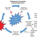
At the time of presentation, many patients with primary and metastatic liver malignancy are outside the transplant criteria (e.g., Milan criteria) or have portal hypertension that renders surgery high risk. Therefore, minimally invasive, catheter-based techniques serve an important treatment role in selected patients with liver malignancy. In current practice, the predominantly used endovascular therapeutic options are transarterial chemoembolization and yttrium-90 (90Y) radioembolization. The fundamental goal in catheter-based techniques is the targeted delivery of therapeutic agents in locally high concentration within the tumor bed via embolic vectors, such as ethiodized oil, particles, and microspheres. The key to success in liver tumor embolization is familiarity with the hepatic arterial anatomy to enable accurate identification and selection of the arteries feeding the tumor and to avoid nontarget embolization.
When surgically placed intra-arterial chemotherapy infusion catheters were used in the early days of liver-directed therapy, a higher rate of complications was noted in the presence of variant arterial anatomy. 1 , 2 Gastroduodenal erosions and ulcerations have been reported after transarterial embolization of hepatocellular carcinoma; these effects are postulated to be due to reflux of embolic agents into the right gastric artery and/or gastroduodenal artery (GDA). 3 , 4 , 5 The risk of hollow viscus injury is potentially much higher with 90Y radioembolization. Inadvertent extra-hepatic infusion of even a very small number of 90Y microspheres can potentially cause erosion, ulceration, and even perforation of the stomach and duodenum. 6 , 7 , 8 , 9 Furthermore, because 90Y-induced gastrointestinal injury is centered at the serosal surface, it may not respond to medical therapy, can be difficult to assess by endoscopy, and may require surgical intervention. 8 , 10
These reports of complications highlight the importance of mastering the standard and variant arterial anatomy, primarily to prevent nontarget embolization. The following discussion reviews the basic angiographic techniques of endovascular liver tumor embolization with special attention to the relevant hepatic and extrahepatic arterial anatomy.
22.2 Basic Angiographic Techniques
All liver tumor embolization procedures begin with diligent angiographic evaluation to detect the visceral arterial anatomy, confirm portal vein patency, identify variant anatomy, find relevant extrahepatic vessels, and assess tumor vascularity. For 90Y radioembolization, this “mapping” angiogram occurs as a separate session 1 to 2 weeks before the infusion procedure and may involve prophylactic embolization of native vessels (e.g., the GDA and right gastric artery) to avoid nontarget delivery of 90Y.
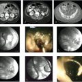
In a typical angiographic evaluation for liver tumor embolization, extensive review of preprocedural cross-sectional imaging, especially the arterial phase, is performed to familiarize the interventional radiologist with the proximal hepatic arterial vasculature. For cases in which high-quality arterial phase computed tomography (CT) or magnetic resonance (MR) imaging is not available for review, an initial aortogram can be performed with a multisidehole catheter to delineate the proximal mesenteric branch vessels. Otherwise, after common femoral arterial access is obtained, initial selection of the superior mesenteric artery (SMA) is performed with a 4- or 5-French diagnostic catheter (▶ Fig. 22.1). Typical injection is at a rate of 3 mL/s for a total of 24 to 30 mL of contrast agent. The presence of replaced hepatic artery from the SMA is assessed (i.e., replaced/accessory right hepatic artery [RHA], replaced proper hepatic artery, or replaced common hepatic artery). Imaging is carried out to the venous phase to evaluate the patency of the central portal veins. Next, the celiac trunk is selected and injected at a rate of 4 mL/s for a total of 15 mL of contrast agent. The hepatic arterial anatomy is interrogated with attention to the presence of replaced/accessory left hepatic artery (LHA), middle hepatic artery, and inferior phrenic arteries. A microcatheter is then coaxially advanced to the common or proper hepatic artery and injected at 4 mL/s for a total of 12 mL. At this point, the GDA, right gastric artery, and any supraduodenal branches should be localized. Subsequently, the LHA and RHA are selected and interrogated with power injection to assess for tumor vascularity and extrahepatic vessels. C-arm cone-beam CT—a technique of reconstructing cross-sectional images from a single rotational fluoroscopic acquisition—is often used in conjunction with planar angiography to increase diagnostic sensitivity and assess tortuous vessel anatomy.

22.3 Anatomy
22.3.1 Conventional Hepatic Arterial Anatomy
In a patient with conventional hepatic arterial anatomy (▶ Fig. 22.2), the celiac artery arises from the ventral surface of the abdominal aorta near the level of the T12 vertebral body. The celiac trunk shortly gives rise to the left gastric artery, which courses superiorly; the splenic artery, which courses to the left; and the common hepatic artery, which courses to the right. This “conventional” celiac trunk anatomy is observed in only approximately 60% of cases. 11 Numerous variations of celiac branching exist, including the presence of separate origins of the main branch vessels directly from the aorta. The common hepatic artery becomes the proper hepatic artery after it gives off the GDA. At the porta hepatis, the proper hepatic artery divides into the LHA and RHA, which supply the respective lobes.

Hepatic parenchymal anatomy is surgically defined by eight Couinaud segments, each with its own portal pedicle that consists of a segmental hepatic artery, portal vein, and bile duct. 12 In conventional arterial anatomy, the RHA feeds hepatic segments V to VIII, and the LHA feeds segments II to IV. Arterial supply to segment IV is variable and may arise as a distinct branch from the proximal RHA or from the RHA/LHA bifurcation (i.e., trifurcation). By convention, this artery is then termed the middle hepatic artery. The caudate lobe (i.e., segment I) is distinct anatomically from the right and left lobes. In a large series of chemoembolization of caudate hepatocellular carcinomas, Miyayama et al 13 found that the segment I artery most commonly arises from the RHA, followed by the LHA, the anterior division of the RHA, and the posterior division of the RHA in almost equal frequency. The variable origin and tiny vessel caliber make it quite challenging to identify and select the caudate artery during tumor embolization.
22.3.2 Common Hepatic Artery Variants
Replaced/Accessory Right Hepatic Artery
A replaced hepatic artery occurs when an entire lobe is supplied by an aberrantly originating artery, whereas an accessory hepatic artery occurs when a portion of the involved lobe is supplied by an aberrant vessel. An accessory hepatic artery is generally considered to supply a unique portion of the liver, rather than being a redundant vessel. 14 The replaced or accessory RHA, which occurs in 10 to 30% of the population, arises from the SMA in almost all cases, usually as the first major branch (▶ Fig. 22.1a). 7 When accessory, an aberrant RHA usually supplies the posterior half of the right lobe (i.e., segments VI and VII). On cross-sectional imaging, the aberrant artery can be seen coursing between the main portal vein and the inferior vena cava.
Replaced/Accessory Left Hepatic Artery
In 12 to 21% of the population, an artery feeding the left hepatic lobe arises from the left gastric artery. 7 The common trunk of the aberrant LHA and the left gastric artery is conventionally termed the gastrohepatic trunk (▶ Fig. 22.3a). The presence of this anatomic variant poses a challenge for embolization of left lobar tumors. Not infrequently, multiple extrahepatic branches, including the inferior phrenic, inferior esophageal, and accessory left gastric arteries, can originate from the gastrohepatic trunk. 8 , 10 Therefore, embolization via the replaced/accessory LHA poses a risk of iatrogenic gastric ulcers. On cross-sectional imaging, the fissure for the ligamentum venosum is an important anatomic landmark; a vascular structure coursing through it may represent the replaced/accessory left hepatic artery, accessory left gastric artery, or inferior esophageal artery (▶ Fig. 22.3b). 10 When treating via the gastrohepatic trunk, the horizontal segment coursing to the right side of the abdomen may have several perforating branches (▶ Fig. 22.3c–f). Branches arising from this horizontal portion should be assumed to perfuse extrahepatic structures. Therefore, embolization should be performed from a location that is distal to the horizontal portion, and reflux must be avoided.

Double Hepatic Artery
The double hepatic artery is seen in approximately 1% of the population. This represents a variant in which there are two separate origins of the hepatic artery from the aorta. This variant can alternatively be thought of as an accessory RHA arising directly from the aorta. An aberrant artery, such as the replaced/accessory RHA or double hepatic artery, should be suspected whenever the celiac arteriography does not opacify the entire liver. Because of rich intrahepatic collateralization, a tumor can be supplied by branches from both hepatic arteries.
Related posts:

Stay updated, free articles. Join our Telegram channel

Full access? Get Clinical Tree


