3 Case-Based Procedure-Related Complications
3.1 Bleeding
3.1.1 Bleeding after Percutaneous Biopsy of Liver Tumor
Patient History
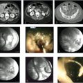
A 70-year-old male with multiple liver tumors suspected hepatocellular carcinoma and portal vein tumor thrombus (Fig. 3‑1 ) received percutaneous needle biopsy to perform genomic analysis of the tumor. He had a medical history of alcoholic hepatitis and diabetes mellitus, but it was well controlled with medication. No coagulopathy was observed.

Initial Treatment
With ultrasonography guidance, two times of percutaneous tumor biopsies through normal liver parenchyma were performed by a hepatobiliary medical oncologist with an 18G Sonopsy needle (Hakko, Tokyo, Japan). A guiding needle was not used.
Problems Encountered during the Treatment
No problems during the procedure were noted.
Imaging Plan
So far no further imaging was planned.
Resulting Complication
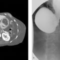
Two hours after the biopsy, the patient showed hemorrhagic shock. The emergent contrast-enhanced CT examination revealed bloody ascites and extravasation in the arterial phase (Fig. 3‑2 ).
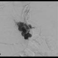
No finding of extravasation was observed on hepatic arterial digital subtraction angiographies (DSAs) at 2 hours after the biopsy. However, CT during hepatic arteriography via the posterior segmental artery showed significant extravasation (Fig. 3‑3 ); therefore, the posterior branch of the right hepatic artery was embolized with 12.5% glue (NBCA:Lipiodol = 1:7). The second angiography was performed 5 hours after the biopsy because of unstable vital signs, and the additional embolization of A6 was carried out without significant finding of extravasation on DSA. However, his vital signs were not improved after the second angiography.
What Would You Do?
Notes:____________________________________________________________________________________________________________________________________________________________________________________________________________________________________________________________________________________________________________________________________________________________________________________________________________________________________________________________________________________________________________________________________________________________________________________________________________________________________________________________________________________________________________________________________________________________________________________________________________________________________________________


Possible Strategies for Complication Management
Third angiography and embolization of the right hepatic artery.
Percutaneous radiofrequency ablation around the biopsy site.
Surgical hemostasis under the laparotomy.
Final Complication Management
Surgical laparotomy was performed. Nonpulsatile bleeding from two biopsy sites was observed, and surgical hemostasis was carried out with electric scalpel (Fig. 3‑4 ).

Complication Analysis
Bleeding complications after liver biopsy might be somewhat challenging to handle. A multidisciplinary approach might be warranted in dedicated cases.
Strategies to Prevent and Take-Home Message
Percutaneous biopsy of liver tumor should be done with guiding needle to reduce the number of punctured hole on liver surface.
Keep in mind that the liver receives blood supply not only from hepatic artery and portal vein, but also from many communicating vessels such as the isolated artery and the capsular arterial plexus. Therefore, the hepatic arterial embolization is not always effective to stop the bleeding from the liver.
If hepatic arterial embolization is not effective for bleeding from the liver, surgical repair should be considered without delay.
Further Reading
Yoshida K, Matsui O, Miyayama S, et al. Isolated arteries originating from the intrahepatic arteries: anatomy, function, and importance in intervention. J Vasc Interv Radiol. 2018; 29(4):531–537.e13.1.2 Hemothorax during Electroporation for Hepatocellular Carcinoma Treatment
Patient History
A 72-year-old female suffering from diabetes mellitus and cirrhosis related to metabolic disease, previously treated with hysterectomy and oophorectomy for endometrial cancer, underwent CT for a 2 cm hepatic nodule detected during surveillance with ultrasound. A hepatocellular carcinoma nodule of 2 cm involving hepatic segment 8/5 was demonstrated (Fig. 3‑5 ).

Initial Treatment
Due to her clinical comorbidities (including bilateral carotid stenosis)—a significant portal hypertension—a percutaneous approach was considered as the treatment of choice. The lesion was clearly visible at a pre-procedural ultrasound (Fig. 3‑6 a) so the patient underwent percutaneous ultrasound-guided irreversible electroporation (Fig. 3‑6 b) under general anesthesia.

Problems Encountered during the Treatment
During the treatment time (about 5 minutes) irregular rhythm was observed, with bradyarrhythmia alternating with tachyarrhythmia. No specific treatment was given; blood pressure and O2 saturation remained stable.
At the end of treatment, the patient reported severe pain, accentuated by breathing, not responding to ketorolac (45 mg) and tramadol (100 mg) administered intravenously. PO2 was reduced (97 under O2 administration).
Imaging Plan
Immediately after the procedure, the patient underwent CT, revealing right basal pleural effusion, with a density of more than 25 HU (Fig. 3‑7 ). After contrast administration, two small blushes of contrast were seen near the two ribs (VII and IX right rib) in the arterial acquisition, increased in the venous phase (Fig. 3‑8 ).


Resulting Complication
Hemothorax due to the puncture of an intercostal artery. No significant decrease in hemoglobin was observed.
What Would You Do?
Notes:____________________________________________________________________________________________________________________________________________________________________________________________________________________________________________________________________________________________________________________________________________________________________________________________________________________________________________________________________________________________________________________________________________________________________________________________________________________________________________________________________________________________________________________________________________________________________________________________________________________________________________________
Possible Strategies for Complication Management
Conservative management (intensive care surveillance).
Percutaneous drainage.
Transcatheter embolization.
Surgery.
Final Complication Management
Conservative management: patient was transferred to the intensive care unit the next day because she showed increased pain and severe dyspnea, decreased hemoglobin (–3 mg/dL), O2 saturation (95 under O2 administration), and increased size of hemothorax at chest X-ray (Fig. 3‑9 ).

The patient was then subjected to blood transfusion and percutaneous drainage of 600 cc of hemorrhagic fluid, with a clear improvement in her clinical picture. She was discharged 10 days later.
Complication Analysis
Sometimes it is rather difficult to determine the exact pathway during intercostal puncture, even when one is aware of the anatomy and the knowledge to pass the needle and any other device on the upper margin of the rib rather than on the lower margin of the rib above. The exact pathway is more difficult to predict in obese patients with an increased body mass index, as the case with the current patient.
Strategies to Prevent and Take-Home Message
Intercostal artery bleeding represents a rather common complication after percutaneous thoracic procedures, with major bleeding only in a few patients.
Management of intercostal artery bleeding events includes transcatheter embolization, with conservative management planned only in stable patients with minor lesions.
Be sure that the needle is inserted over the top of the rib (superior margin) to avoid the intercostal nerves and blood vessels that run on the underside of the rib.
Further Reading
Pieper M, Schmitz J, McBane R, et al. Bleeding complications following image-guided percutaneous biopsies in patients taking clopidogrel: a retrospective review. J Vasc Interv Radiol. 2017; 28(1):88–93 Broderick SR. Hemothorax: etiology, diagnosis, and management. Thorac Surg Clin. 2013; 23(1):89–96, vi–vii3.1.3 Cervical Hematoma after Thyroid Fine Needle Aspiration Biopsy
Patient History
A 52-year-old patient was diagnosed with a thyroid nodule during physical examination, which was confirmed on follow-up ultrasound (Fig. 3‑10 , Fig. 3‑11 , Fig. 3‑12 ).


Initial Treatment
To further evaluate the thyroid nodule, a fine needle aspiration biopsy was conducted under ultrasound guidance (22G). Three samples were obtained.
Problems Encountered during the Treatment
The patient developed neck swelling and dyspnea after procedure.
Imaging Plan
A CT scan of the neck soft tissue was performed, which demonstrated right cervical hemorrhage associated with left-warded deviation of the trachea.
Resulting Complication
An extensive post-procedure right cervical hematoma, within the right thyroid lobe, was developed after the procedure.
What Would You Do?
Notes:____________________________________________________________________________________________________________________________________________________________________________________________________________________________________________________________________________________________________________________________________________________________________________________________________________________________________________________________________________________________________________________________________________________________________________________________________________________________________________________________________________________________________________________________________________________________________________________________________________________________________________________
Possible Strategies for Complication Management
Breathing support.
Surgical exploration of the neck and drainage of the hematoma.
Final Complication Management
The surgical exploration of the neck revealed a large hematoma in the neck soft tissue without the evidence of active hemorrhage.
Complication Analysis
Insufficient compression over the punctuation site could result in post-biopsy hemorrhage and subsequent hematoma within the thyroid gland.
Strategies to Prevent and Take-Home Message
Medication list should be checked before any intervention and adjusted appropriately.
International normalized ratio and platelet levels should be determined before any intervention. Patients with increased risk of bleeding should be addressed accordingly with vitamin K substitution, cryoprecipitate, or fresh frozen plasma before biopsy or while encountering bleeding.
Fine needle aspiration should never be conducted without ultrasound surveillance.
Compression over the punctuation site should be performed to minimize the risk of post-procedural hemorrhage.
Further Reading
Ha EJ, Baek JH, Lee JH, et al. Complications following US-guided core-needle biopsy for thyroid lesions: a retrospective study of 6,169 consecutive patients with 6,687 thyroid nodules. Eur Radiol. 2017; 27(3):1186–1194 Akbaba G, Omar M, Polat M, et al. Cutaneous sinus formation is a rare complication of thyroid fine needle aspiration biopsy. Case Rep Endocrinol. 2014; 2014:923438 Lee YJ, Kim DW, Jung SJ. Comparison of sample adequacy, pain-scale ratings, and complications associated with ultrasound-guided fine-needle aspiration of thyroid nodules between two radiologists with different levels of experience. Endocrine. 2013; 44(3):696–701 Noordzij JP, Goto MM. Airway compromise caused by hematoma after thyroid fine-needle aspiration. Am J Otolaryngol. 2005; 26(6):398–3993.1.4 Hepatic Intraparenchymal Hemorrhage after CT-Guided Liver Biopsy
Patient History
A 55-year-old male with suspected hepatitis was scheduled for liver biopsy. No further comorbidities were present.
Initial Treatment and Imaging Plan
CT-guided percutaneous liver biopsy (16G).
Problems Encountered during the Treatment
The patient tolerated the procedure well, without any complication. The patient was discharged home.
Resulting Complication
The patient arrived to emergency room 6 hours after discharge, complaining of abdominal pain. On the physical examination, the patient was found to have tachycardia and hypotension. Contrast-enhanced CT scan of the abdomen revealed a hepatic intraparenchymal hemorrhage (Fig. 3‑13 , Fig. 3‑14 , Fig. 3‑15 , Fig. 3‑16 ).


What Would You Do?
Notes:____________________________________________________________________________________________________________________________________________________________________________________________________________________________________________________________________________________________________________________________________________________________________________________________________________________________________________________________________________________________________________________________________________________________________________________________________________________________________________________________________________________________________________________________________________________________________________________________________________________________________________________
Possible Strategies for Complication Management
Conservative treatment.
Local injection of Gelfoam immediately after biopsy.
Embolization of the feeding vessel by using a microcatheter, selective injection of Gelfoam, glue, large particles, or coil.
Surgical ligation (if an endovascular approach fails).
Final Complication Management
Angiography of hepatic vessels revealed no active hemorrhage. The patient was treated conservatively without embolization.
Complication Analysis
A small branch of the right hepatic artery was likely injured during the procedure, resulting in hemorrhage and hematoma. However, the hematoma remained undetected on the post-biopsy scan. The patient presented with symptomatic hemodynamic instability later.
Strategies to Prevent and Take-Home Message
Medications should be checked before any intervention and adjusted appropriately.
International normalized ratio and platelet levels should be determined before the intervention. Patients who are at increased risk of bleeding may benefit from vitamin K substitution, fresh frozen plasma, and cryoprecipitate before biopsy.
Post-biopsy scan of the entire liver should be obtained.
Patient’s vital signs should be monitored at least for 2 to 4 hours post-biopsy.
Further Reading
Sag AA, Brody LA, Maybody M, et al. Acute and delayed bleeding requiring embolization after image-guided liver biopsy in patients with cancer. Clin Imaging. 2016; 40(3):535–540 Bishehsari F, Ting PS, Green RM. Recurrent gastrointestinal bleeding and hepatic infarction after liver biopsy. World J Gastroenterol. 2014; 20(7):1878–1881 Bannas P, Habermann CR, Yamamura J, Bley TA. Severe haemorrhage after liver biopsy of malignant B-cell lymphoma mimicking hepatic infection. RoFo Fortschr Geb Rontgenstr Nuklearmed. 2013; 185(2):164–1663.1.5 Hemodynamic Instability, Presumed to be Related to Worsening Retroperitoneal Hemorrhage during and after Cryoablation for Renal Tumor Treatment
Patient History
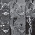
A 67-year-old female with a growing 4.2 cm left upper pole renal mass was scheduled for percutaneous cryoablation of her tumor because of her significant medical comorbidities. Given the size of the tumor, a preablative embolization to minimize the risk of bleeding was scheduled.
Initial Treatment and Imaging Plan
Initial left renal angiography via left radial arterial access demonstrated no clear vascular supply to the targeted lesion. A small round blush was seen related to an adrenal branch from the left renal capsular artery, which was thought to represent the targeted tumor. Attempts were made to embolize this lesion; however, the catheter kept spontaneously sliding out of the selected branch, and after multiple attempts, the catheter was only able to be transiently seated in the targeted vessel. About 1/20 of one vial of 100 to 300 µm Embospheres was injected before the catheter popped out again. No further embolization attempts were performed, and the decision was made to proceed with CT-guided cryoablation. The patient was then intubated electively due to poor baseline respiratory status. The patient was placed in the prone position in the CT scanner, and then four IceForce probes (Galil Medical Inc., Arden Hills, MN , USA) were inserted through the left flank into the targeted tumor. Cryoablation proceeded with two 10-minute freeze cycles and an intervening 8-minute thaw cycle. The probes were then removed.
Problems Encountered during the Treatment
During the procedure, a moderate-sized retroperitoneal hematoma developed. Its size remained stable at the end of the procedure and the patient was hemodynamically stable throughout. At the end of the procedure, the patient was sent to the post-anesthesia recovery unit, where she was extubated. She then exhibited profound hypotension requiring vasopressor support. Due to her instability, no follow-up CT scan could be performed. Instead she was reintubated, and brought back to interventional radiology for angiography and embolization of a presumed worsening retroperitoneal hemorrhage.
Resulting Complication
Hypotension and hemodynamic instability, presumed to be related to worsening retroperitoneal hemorrhage (Fig. 3‑17 , Fig. 3‑18 , Fig. 3‑19 ).


What Would You Do?
Notes:____________________________________________________________________________________________________________________________________________________________________________________________________________________________________________________________________________________________________________________________________________________________________________________________________________________________________________________________________________________________________________________________________________________________________________________________________________________________________________________________________________________________________________________________________________________________________________________________________________________________________________________
Possible Strategies for Complication Management
Catheterization of the feeding vessel, for example, by using a microcatheter, followed by selective coil embolization.
Alternative agents for embolization: glue, large particles, Gelfoam.
Surgery (if an endovascular approach fails).
Final Complication Management
Angiography including the aorta, left renal artery, left inferior phrenic artery, upper left lumbar arteries, lower left intercostal arteries, and capsular branch of the left renal artery was performed, showing no evidence of active extravasation. Empiric embolization to stasis of the capsular branch of the left renal artery using 100 to 300 µm Embospheres (Merit Medical, Jordan, UT, USA) was performed. Postembolization CT in retrospect showed no evidence of expansion of the hematoma compared to the scan ablation images, refuting the initial assumption that hypotension had resulted from worsening hemorrhage. The next day, the patient was extubated and discharged home without event.
Complication Analysis
The initial angiography demonstrated a small sub-branch of the capsular branch supplying a small rounded tumor. At the time, it was thought that this tumor was a component of the patient’s large renal cell carcinoma (Fig. 3.21, Fig. 3.22). However, this lesion in retrospect represented the patient’s known left adrenal nodule, embolization of which may have resulted in hypoadrenergic state and caused hypotension. Alternatively, her episode may have been related to anesthesia.
Strategies to Prevent and Take-Home Message
Consider the reasonability of embolization of hypovascular tumors (Fig. 3‑23 , Fig. 3‑24 ).

Fig. 3.23 Nonenhanced CT scan of abdomen demonstrates the postablation hematoma and perinephric inflammatory changes. 
Fig. 3.24 One-month follow-up contrast-enhanced CT scan of the upper abdomen demonstrates the ablation cavity within the right renal upper pole with interval significant improvement of the perinephric inflammatory stranding.
Further Reading
Schmit GD, Schenck LA, Thompson RH, et al. Predicting renal cryoablation complications: new risk score based on tumor size and location and patient history. Radiology. 2014; 272(3):903–910 Chen JX, Guzzo TJ, Malkowicz SB, et al. Complication and readmission rates following same-day discharge after percutaneous renal tumor ablation. J Vasc Interv Radiol. 2016; 27(1):80–86 Atwell TD, Carter RE, Schmit GD, et al. Complications following 573 percutaneous renal radiofrequency and cryoablation procedures. J Vasc Interv Radiol. 2012; 23(1):48–543.1.6 Mediastinal Hemorrhage and Hemothorax after Anterior Mediastinal Puncture
Patient History
A 48-year-old male was scheduled for biopsy of an anterior mediastinal mass. The patient had no further comorbidities.
Initial Treatment and Imaging Plan
CT-guided percutaneous biopsy was performed using an 18-gauge coaxial biopsy system through parasternal approach.
Problems Encountered during the Treatment
The patient developed tachycardia and hypotension during the treatment.
Resulting Complication
CT scan of the chest demonstrated a mediastinal hemorrhage and hemothorax (Fig. 3‑25 , Fig. 3‑26 , Fig. 3‑27 , Fig. 3‑28 ).


What Would You Do?
Notes:____________________________________________________________________________________________________________________________________________________________________________________________________________________________________________________________________________________________________________________________________________________________________________________________________________________________________________________________________________________________________________________________________________________________________________________________________________________________________________________________________________________________________________________________________________________________________________________________________________________________________________________
Possible Strategies for Complication Management
Conservative treatment.
Selective embolization of the supplying vessel by Gelfoam, glue, large particles, or coil using a microcatheter.
Surgical ligation (if the endovascular approach fails).
Final Complication Management
The patient was treated conservatively.
Complication Analysis
The biopsy needle injured the internal mammary artery, leading to the hemorrhage. Alternatively, the bleeding might originate from the mass itself or from the pleura.
Strategies to Prevent and Take-Home Message
Contrast-enhanced CT or MRI should be obtained before the biopsy. Careful anatomical evaluation is necessary to identify abutting vascular lesions.
For vascularized lesions, needles with small diameter should be utilized to minimize the risk of vascular injury and hemorrhage.
The internal mammary vessels can be preserved by aiming medial to the vessels and advancing needle adjacent to the sternum or lateral to the vessels.
Injection of contrast during procedure may help to better determine the anatomical structures and differentiate lymph nodes and vasculature.
Patients should be observed for 1 to 3 hours after procedure.
Further Reading
Barker JM, Sahn SA. Opacified hemithorax with ipsilateral mediastinal shift after transthoracic needle biopsy. Chest. 2003; 124(6):2391–2392 Giron J, Fajadet P, Senac JP, Durand G, Benezet O, Didier A. [Diagnostic percutaneous thoracic punctures. Assessment through a critical study of a compliation of 2406 cases]. Rev Mal Respir. 1996; 13(6):583–590 Berquist TH, Bailey PB, Cortese DA, Miller WE. Transthoracic needle biopsy: accuracy and complications in relation to location and type of lesion. Mayo Clin Proc. 1980; 55(8):475–4813.1.7 Hemoptysis after Percutaneous Lung Biopsy
Patient History
A 75-year-old immunocompromised patient presented with a clinical history of chronic dyspnea. Conventional radiography and follow-up contrast-enhanced CT of the chest showed a left paramediastinal mass, raising a concern for tuberculosis.
Initial Treatment
A CT-guided percutaneous lung biopsy using an 18-gauge coaxial biopsy system was performed to obtain a tissue sample (Fig. 3.29).
Problems Encountered during the Treatment
Subsequent to the biopsy, the patient developed hemoptysis.
Imaging Plan
A CT angiography of the chest was immediately performed demonstrating a left lower lobe segmental pulmonary artery pseudoaneurysm.
Resulting Complication
A pulmonary artery injury could happen as a complication of biopsy. In this case, a pseudoaneurysm of the left lower lobe segmental pulmonary artery occurred during biopsy (Fig. 3‑30 , Fig. 3‑31 , Fig. 3‑32 ).


What Would You Do?
Notes:____________________________________________________________________________________________________________________________________________________________________________________________________________________________________________________________________________________________________________________________________________________________________________________________________________________________________________________________________________________________________________________________________________________________________________________________________________________________________________________________________________________________________________________________________________________________________________________________________________________________________________________
Possible Strategies for Complication Management
Embolization of the pseudoaneurysm using Gelfoam, glue, or coil.
Final Complication Management
Initial selective angiography was performed to determine the anatomical location of the pseudoaneurysm. Embolization of the pseudoaneurysm was then performed by packing microcoils within the pseudoaneurysm sac. Finally, complete occlusion of the pseudoaneurysm sac was yielded.
Complication Analysis
A pulmonary artery was injured during the percutaneous lung biopsy, resulting in development of pseudoaneurysm.
Strategies to Prevent and Take-Home Message
Post biopsy cross-sectional images should be obtained immediately after removing the biopsy needle.
The patient’s vital signs should be monitored at least for 2 hours.
Further Reading
Hwang EJ, Park CM, Yoon SH, Lim HJ, Goo JM. Risk factors for haemoptysis after percutaneous transthoracic needle biopsies in 4,172 cases: Focusing on the effects of enlarged main pulmonary artery diameter. Eur Radiol. 2018; 28(4):1410–1419 Heerink WJ, de Bock GH, de Jonge GJ, Groen HJ, Vliegenthart R, Oudkerk M. Complication rates of CT-guided transthoracic lung biopsy: meta-analysis. Eur Radiol. 2017; 27(1):138–148 Tai R, Dunne RM, Trotman-Dickenson B, et al. Frequency and severity of pulmonary hemorrhage in patients undergoing percutaneous CT-guided transthoracic lung biopsy: single-institution experience of 1175 cases. Radiology. 2016; 279(1):287–2963.1.8 Delayed Bleeding after Biliary Drainage
Patient History
A 70-year-old female with history of unresectable pancreatic tumor was admitted to the emergency room with jaundice, fever, and dull abdominal pain. CT scan showed a 2 cm lesion (Fig. 3‑33 a) of the uncinated process of the pancreas, with encasement of superior mesenteric artery (Fig. 3‑33 b), undissociable from the third portion of the duodenum (Fig. 3‑33 c), with compression of the Vater papilla and subsequent dilation of the intra- and extrahepatic biliary tree (Fig. 3‑33 b–d). Laboratory examination revealed high value of bilirubin (12 mg/dL), liver enzymes (especially GGT: 320 U/L, normal values: 12–48 U/L), and CA19.9 (800 U/mL, normal values < 35U/mL).

Initial Treatment
To reduce cholestasis, an 8 French internal–external drainage (Fig. 3‑34 ) was placed through ultrasound puncture of the segment 3 biliary duct, with its apex in the duodenum, passing the papillary stenosis.

Problems Encountered during the Treatment
No immediate complication was demonstrated; in particular amylase/lipase levels remained in the normal range. Bilirubin values progressively decreases and the patient was discharged 4 days later (bilirubin 3 mg/dL).
Imaging Plan
Ultrasound in order to gain any information about the progress of drainage; in case of limited information due to artifacts like bowel air, a contrast-enhanced CT will be scheduled.
Resulting Complication
Two weeks after the procedure, due to liver enzyme increase, the internal–external drainage was replaced first with a 10 French and then with a 12 French.
One month after the procedure the patient was admitted to the emergency room, with gross haemobilia. Laboratory examination showed low hemoglobin level (8 g/dL, normal values: 3.5–17.5 g/dL).
What Would You Do?
Notes:____________________________________________________________________________________________________________________________________________________________________________________________________________________________________________________________________________________________________________________________________________________________________________________________________________________________________________________________________________________________________________________________________________________________________________________________________________________________________________________________________________________________________________________________________________________________________________________________________________________________________________________
Possible Strategies for Complication Management
Conservative treatment (surveillance, with hemoglobin evaluation every 6 hours).
CT evaluation.
Review and eventual replacement of the biliary drainage.
Surgery.
Final Complication Management
Evaluation of the biliary drainage: during the drainage removal a jet blood leak was demonstrated and contrast injection through the sheath showed an arterial leakage (Fig. 3‑35 a).

Catheterization of celiac trunk was performed with a 5 French reverse curve catheter, with a 3 French microcatheter a leak from the segment 4 hepatic artery (Fig. 3‑35 b), and a communication between the biliary tree and the segmental hepatic artery were revealed. The small leakage was treated with absorbable gel foam and detachable coil embolization (Fig. 3‑35 c).
After the procedure a 14 French internal–external biliary drainage (Fig. 3‑35 d) was placed.
Complication Analysis
Iatrogenic injuries secondary to percutaneous biliary drain placement are rare, usually manifesting 1 to 7 days after the procedure; vascular bleeding, instead, is a late finding and the only symptom may be persistent hemobilia.
Hemobilia may be due to arterial or venous bleeding. In each case, the interventional radiologist may embolize (gel foam and coils) the offending vessel, with other alternatives being balloon tamponade or stent placement. Aggressive arterial embolization may lead to vascular compromise, especially in the setting of portal vein occlusion, so the interventional radiologist should be aware of this further complication.
Strategies to Prevent and Take-Home Message
A careful follow-up of the patient is of utmost importance since iatrogenic injuries secondary to percutaneous biliary drain placement are rare and usually occur 1 to 7 days after the procedure.
Further Reading
Ernst O, Sergent G, Mizrahi D, Delemazure O, L’Herminé C. Biliary leaks: treatment by means of percutaneous transhepatic biliary drainage. Radiology. 1999; 211(2):345–348 Born P, Rösch T, Sandschin W, Weiss W. Arterial bleeding as an unusual late complication of percutaneous transhepatic biliary drainage. Endoscopy. 2003; 35(11):978–979 Lynskey GE, Banovac F, Chang T. Vascular complications associated with percutaneous biliary drainage: a report of three cases. Semin Intervent Radiol. 2007; 24(3):316–3193.1.9 Bleeding during Diagnostic CT-Guided Liver Puncture
Patient History
A 74-year-old male patient with a 10 cm lesion of the right liver lobe, involving segments 5 and 6 was scheduled for CT-guided diagnostic puncture in order to obtain the exact diagnosis. Due to medical history and laboratory changes, a hepatocellular carcinoma was suspected. Diagnostic-enhanced CT scan has depicted a hypodense lesion with some enhancing vessel-like appearing areas inside (Fig. 3‑36 ). Native T1 MRI showed a larger appearance of the lesion reaching to the liver capsule. The high intense signal of the main lesion was interpreted as products of blood (Fig. 3‑37 ).


Initial Treatment
So far no treatment was done. The diagnostic procedure was planned for further diagnostic reasons in order to offer the patient an individualized treatment concept.
Diagnostic puncture was done under local anesthesia with 10 mL Prilocaine hydrochloride 1%. The body was elevated for 45 degrees in order to start percutaneous access in the posterior axillary line. After skin incision, 16G 6 cm trocar (Quick-Core Biopsy Needle Set, Cook, Bloomington, IN, USA) was inserted and after checking the adequate position, an 18G 9 cm biopsy needle was inserted and 5 probes were successfully taken.
Problems Encountered during the Treatment
After the last probe, some pulsatile bleeding through the trocar needle appeared.
Imaging Plan
No initial imaging was planned to beat the bleeding complication.
Resulting Complication
Bleeding during diagnostic liver puncture.
What Would You Do?
Notes:____________________________________________________________________________________________________________________________________________________________________________________________________________________________________________________________________________________________________________________________________________________________________________________________________________________________________________________________________________________________________________________________________________________________________________________________________________________________________________________________________________________________________________________________________________________________________________________________________________________________________________________
Possible Strategies for Complication Management
Retrograde puncture of the femoral groin. Placement of a 4 French sheath into the ipsilateral common femoral artery. Catheterization of the coeliac trunk with 4 French Cobra catheter and performing diagnostic angiography in order to visualize a potential bleeding source, that is, coming from right hepatic artery branches. If this would be the case, an embolization procedure (coils, glue, particles) via a coaxially placed microcatheter could be performed.
Embolization via the trocar using gel foam until the bleeding stops.
Surgical, laparoscopic evaluation, and potential treatment of the source of the bleeding.
Final Complication Management
Embolization via the trocar using gel foam until the bleeding stops.
Complication Analysis
During puncture and biopsy vessel damage occurred, either a portal vein branch or a hepatic artery branch, resulting in permanent bleeding trough the inserted trocar. Due to the fact that nearly no covering regular liver tissue between malignant lesion and liver capsule existed, the risk of intraperitoneal bleeding is slightly higher than with a zone of nondiseased tissue in between.
Strategies to Prevent and Take-Home Message
Handle instruments with care. Try to find a way to reach the lesion through a surrounding zone of nondiseased liver tissue. This will prevent, in case of vessel injury, a significant bleeding through the puncture channel, since the nondiseased tissue will close this channel rather fast in case of minor, low pressure bleeding.
In case of bleeding through the puncture needle, keep the needle stable in place and close the puncture channel mechanically. Before discharge, the puncture sites should be evaluated by ultrasound or native CT to check for any bleeding complications (hematoma, fluid intraperitoneal).
The most critical aspect of management of complications such as bleeding, pneumothorax, and visceral perforation is to recognize that one these complications has occurred during liver biopsy.
Further Reading
van Beek D, Funaki B. Hemorrhage as a complication of percutaneous liver biopsy. Semin Intervent Radiol. 2013; 30(4):413–416 Sandrasegaran K, Thayalan N, Thavanesan R, et al. Risk factors for bleeding after liver biopsy. Abdom Radiol (NY). 2016; 41(4):643–649 Kennedy SA, Milovanovic L, Midia M. Major bleeding after percutaneous image-guided biopsies: frequency, predictors, and periprocedural management. Semin Intervent Radiol. 2015; 32(1):26–333.1.10 Bleeding after Radiofrequency Ablation for Hepatocellular Carcinoma Treatment
Patient History
An 80-year-old female patient was planned for percutaneous thermal ablation of subcapsular hepatocellular carcinoma in the second segment (Fig. 3‑38 ). She had a Child’s class B without other comorbidities. Before the procedure, laboratory tests were evaluated, especially blood coagulation function, presenting normal values.

Initial Treatment
The patient was scheduled for radiofrequency ablation (RFA). RFA was performed using real-time ultrasound guidance under conscious sedation. Every effort was made in order to minimize the number of transgression of the liver capsule and to traverse sufficient normal liver parenchyma. Cauterization of the needle tract was also performed.
Problems Encountered during the Treatment
No complications were reported during the procedure, total necrosis of the tumor was achieved.
Imaging Plan
Contrast-enhanced CT performed as control check after 3 hours showed an active and massive abdominal bleeding (Fig. 3‑39 ) from an injured vessel posterior to the left liver lobe, suggesting rupture of the lesion.

What Would You Do?
Notes:____________________________________________________________________________________________________________________________________________________________________________________________________________________________________________________________________________________________________________________________________________________________________________________________________________________________________________________________________________________________________________________________________________________________________________________________________________________________________________________________________________________________________________________________________________________________________________________________________________________________________________________
Possible Strategies for Complication Management
Blood transfusion.
Transarterial embolization.
Surgery.
Final Complication Management
Emergency transfemoral hepatic arterial embolization via transfemoral approach was performed as diagnostic (Fig. 3‑40 ) and therapeutic procedure. Immediately after the detection of the bleeding point (Fig. 3‑41 ), transarterial embolization was performed with microcoils (Fig. 3‑42 ). The bleeding was stopped, as also suggested by the improvement of the clinical and laboratory data.


Complication Analysis
Hemorrhage is one of the most common major complications occurring during RFA. Several factors are related to bleeding. The most important risk factor in our case was the location of the lesion: it was subcapsular and adjacent to a major blood vessel injured due to direct mechanical trauma by electrode needle. Physician performing RFA have to pay attention to the localization of the lesion and they must be cognizant of the diagnosis and treatment of a possible bleeding.
Strategies to Prevent and Take-Home Message
Screening for coagulopathy should be performed before RFA.
It is important to be careful if the lesion is subcapsular, minimizing the number of transgressions of the liver capsule.
An accurate monitoring of hemodynamic parameters during procedure is mandatory.
Contrast-enhanced CT is the choice for the detection end evaluation of post-procedural bleeding, even if in some centers contrast-enhanced ultrasound is used for immediate post-procedural control.
Further Reading
Rhim H, Yoon KH, Lee JM, et al. Major complications after radio-frequency thermal ablation of hepatic tumors: spectrum of imaging findings. Radiographics. 2003; 23(1):123–134, discussion 134–136 Rhim H. Complications of radiofrequency ablation in hepatocellular carcinoma. Abdom Imaging. 2005; 30(4):409–418 Park JG, Park SY, Tak WY, et al. Early complications after percutaneous radiofrequency ablation for hepatocellular carcinoma: an analysis of 1,843 ablations in 1,211 patients in a single centre: experience over 10 years. Clin Radiol. 2017; 72(8):692.e9–692.e153.1.11 Massive Pleural Hemorrhage after Lung Radiofrequency Ablation
Patient History
A 57-year-old man with history of lung metastases for colorectal cancer had video assisted thoracic surgery for wedge resection of a single lung metastasis in the right upper lobe 20 months ago. Patient had a CT-guided radiofrequency in the right lower lobe 8 months ago for a single 12 mm lung metastasis. On follow-up CT-imaging, a scar (white arrow) as well as a new location of lung metastasis in the right lower lobe (red arrow; Fig. 3‑43 a) can be seen. Tumor board decision was again in favor for RFA.

Initial Treatment
Lung RFA is performed under general anesthesia in the prone position. After single puncture, paravertebral placement of a LeVeen radiofrequency electrode was done successfully (Boston Scientific, Nattick, MA, USA) under CT guidance (Fig. 3‑43 b).
Problems Encountered during the Treatment
After completion of RFA treatment, patient is placed in the supine position and a pleural effusion is seen; after 10 minutes of observation, a second CT scan is obtained while the blood pressure drops and the heart rate accelerates (Fig. 3‑44 ).

Resulting Complication
Massive pleural hemorrhage.
What Would You Do?
Notes:____________________________________________________________________________________________________________________________________________________________________________________________________________________________________________________________________________________________________________________________________________________________________________________________________________________________________________________________________________________________________________________________________________________________________________________________________________________________________________________________________________________________________________________________________________________________________________________________________________________________________________________
Possible Strategies for Complication Management
Watchful follow-up.
Pleural drainage.
Pulmonary angiogram.
Bronchial angiogram.
Intercostal angiogram.
Final Complication Management
Angiogram is performed in the same room (angio-CT room) with selective catheterization of right intercostal branches (arrow) running toward the vicinity at previous puncture site (Fig. 3‑45 a). Extravasation of contrast to the pleura (arrow) is seen on the digital subtracted angiogram at a later phase (Fig. 3‑45 b).

Coil embolization (white arrows) was performed in sandwich technique to stop arterial bleeding (black arrow; Fig. 3‑45 c).
Pleural drainage is then performed with a 26 French drainage catheter and aspiration of 700 cc of coagulated blood was also done (underlining the need for a very large size and lumen catheter). Patient recovered after 48 hours at the intensive care unit and was discharged at day 4 after treatment.
Complication Analysis
Pleural hemorrhage due to intercostal artery damage during the puncture.
Strategies to Prevent and Take-Home Message
Accidental puncture of the intercostal artery might happen when performing diagnostic or therapeutic needle insertion into lung or pleura space. Any pleural effusion, which rapidly increases and diagnosed on control CT, must induce an angiogram for potential intervention like an embolization procedure. The risk of injuring the intercostal artery is higher when intercostal puncture is performed in the paravertebral region. Here the intercostal artery runs between the ribs without the protection from the bone of the lateral or anterior aspect of the ribs. During endovascular treatment of this complication, the curve of the guidewire is noted in the proximal part of the intercostal artery (black arrow), meaning it is running midway in between the ribs and the artery is prone for the risk of inadvertent puncture at this level, while on its more distal/peripheral part the subcostal artery pathway is below the ribs inferior margin (white arrow) with much lower risk of inadvertent puncture, especially if a puncture is performed immediately above the rib margin ( Fig. 3‑46 ). When intercostal puncture is needed in the paravertebral area, a likely valid option to minimize the risk of harming the intercostal artery could be using a blunt needle when traversing the muscle.

Further Reading
McAllister M, Lim K, Torrey R, Chenoweth J, Barker B, Baldwin DD. Intercostal vessels and nerves are at risk for injury during supracostal percutaneous nephrostolithotomy. J Urol. 2011; 185(1):329–334 Li BQ, Ye B, Chen FX, et al. Intercostal artery damage and massive hemothorax after thoracocentesis by central venous catheter: a case report. Chin J Traumatol. 2017; 20(5):305–307 Lai JH, Yan HC, Kao SJ, Lee SC, Shen CY. Intercostal arteriovenous fistula due to pleural biopsy. Thorax. 1990; 45(12):976–9783.1.12 Delayed Bleeding after Microwave Ablation for a Recurrent Colorectal Liver Metastasis
Patient History
A 65-year-old male with metastatic colon carcinoma with prior liver resection, systemic and HAIP (hepatic arterial pump) chemotherapy, with new 20 × 23 × 30 mm recurrent metastasis at the surgical resection margin along the border of the left hemi-liver, detected on routine surveillance CT examination. On review of the case and multidisciplinary discussion, the patient was deemed a good candidate for thermal microwave (MW) ablation.
Initial Treatment
The patient underwent percutaneous MW ablation under general anesthesia as per standard clinical practice. The goal of the procedure was to treat the entire tumor with at least 1 cm circumferential minimal ablation margin. Since the tumor was (fluorodeoxyglucose) FDG-avid, the split-dose 18F-FDG PET/CT technique was used for tumor localization, MW electrode placement, as well as confirmation of complete ablation and immediate assessment of technical success (Fig. 3‑47 ).

After careful imaging consideration, three overlapping ablations were performed utilizing three Neuwave PR 15 electrodes (Ethicon, Madison, Wisconsin, USA), with real-time prophylactic hydrodissection of the colon. The treatment protocol utilized for each ablation session was 65 W for a total of 6 minutes (two overlaps were performed with two electrodes, a third overlap ablation was performed with three electrodes), with temperature monitoring at the intended ablation margin (until reaching 70°C; Fig. 3‑48 ).

Pre- and postablation biopsies were performed within institution research protocol with specimens obtained from the ablation zone center, ablation margin, as well as from the electrodes. There was no evidence of viable tumor post-MW ablation.
Problems Encountered during the Treatment
None. Patient was successfully treated with MW ablation. Both immediate postablation 18F-FDG PET/CT ( Fig. 3‑49 ) and three-phase contrast-enhanced CT scans demonstrated complete ablation of the tumor, with ablation zone size of 60 × 45 × 50 mm.

Imaging Plan
Patient was scheduled for multiphase abdominal CT scan within 4 to 6 weeks after ablation, in order to confirm technical success/complete ablation; this was to serve as the new baseline for future comparisons.
Resulting Complication
Three weeks after the procedure, the patient presented to interventional radiology clinic with vague right upper quadrant pain, radiating to the back. The patient had decreased hemoglobin concentration (8.6 g/dL, baseline level-12.3 g/dL), mild thrombocytopenia (136 K/mcl), and norman white blood cell count (4.6 K/mcl). A contrast-enhanced CT scan was obtained at that time, this demonstrated a 50 mm pseudoaneurysm within the ablation zone with active hemorrhage (Fig. 3‑50 ).

What Would You Do?
Notes:____________________________________________________________________________________________________________________________________________________________________________________________________________________________________________________________________________________________________________________________________________________________________________________________________________________________________________________________________________________________________________________________________________________________________________________________________________________________________________________________________________________________________________________________________________________________________________________________________________________________________________________
Possible Strategies for Complication Management
Embolization of the pseudoaneurysm and feeding vessels.
Covered stent placement isolating the pseudoaneurysm with possible embolization.
Conservative “watch and wait” approach with close monitoring of the hemoglobin, hematocrit, and vital signs. However, it is not acceptable option in the case of active extravasation.
Percutaneous or transcatheter thrombin injection within the pseudoaneurysm.
Final Complication Management
The patient was transferred to the hospital where he underwent a diagnostic angiogram and embolization.
Digital subtraction angiography (DSA) was performed in the celiac and proper hepatic arteries with a 5 French Simmons 2 catheter (Angiodynamic, Latham, NY, USA). Additionally, superselective DSA was performed within the segment 4 and segment 2/3 arteries using a renegade microcatheter (Boston Scientific, Marlborough, MA, USA). Multifocal extravasation of contrast medium was identified from the hepatic segment 4 artery (Fig. 3‑51 ). Embolization was performed utilizing Nester coils (Cook Medical, Bloomington, IN, USA): seven 4 mm × 7 cm coils, five 3 mm × 7 cm coils, two 6 mm × 7 cm coils, as well as one 2 mm × 4 cm detachable Ruby coil (Penumbra, Alameda, CA, USA) until hemostasis was achieved. The patient was successfully managed with coil embolization of the vessels feeding the pseudoaneurysm. He remained alive with no local tumor progression in the ablation zone and outside the liver as of last follow-up 2 years post-MW ablation.

Complication Analysis
Injury to adjacent vessels and bile ducts are rare but well-known complications of the thermal ablation. The goal of ablation with curative intent is to create margins of at least 5 mm, and ideally 10 mm circumferentially around the target tumor. This patient presented with a relatively large liver lesion (> 3 cm) in a challenging location, these factors increased risk of complications following MW ablation. Although the patient’s complications were successfully managed and the patient was alive on last follow-up 2 years following initial treatment, the location was challenging and required special maneuvers. In such cases intra-arterial therapies including 90Y radiation segmentectomy or DEBIRI TACE (beads loaded with 100 mg of irinotecan) could be considered instead of ablation, although the long-term outcomes of such therapies are not as well studied as with thermal ablation.
Strategies to Prevent and Take-Home Messages
When treating secondary liver malignancies with a curative intent using percutaneous ablation, minimal ablation margins greater than 5 mm and ideally 10 mm circumferentially are necessary to achieve long-term local tumor control.
Be aware of the potential increase in the complication risk when using thermal ablation (especially MW ablation) for large (> 3 cm) lesions, requiring multiple electrodes and overlapping ablations, especially in patient with prior hepatic artery infusion pump (HAIP) chemotherapy.
90Y radiation segmentectomy or DEBIRI TACE could be considered instead of ablation for large lesions in challenging location, although the long-term outcomes of such therapies are not as well studied as with thermal ablation.
Further Reading
Liang P, Wang Y, Yu X, Dong B. Malignant liver tumors: treatment with percutaneous microwave ablation—complications among cohort of 1136 patients. Radiology. 2009; 251(3):933–940 Kwon HJ, Kim PN, Byun JH, et al. Various complications of percutaneous radiofrequency ablation for hepatic tumors: radiologic findings and technical tips. Acta Radiol. 2014; 55(9):1082–10923.2 Cement Extravasation
3.2.1 Pulmonary Cement Embolization after Vertebroplasty for Lumbar Fracture Treatment
Patient History
An 80-year-old male patient suffering from a single-level osteoporotic vertebral compression fracture (L3) and pain was scheduled for a minimal invasive treatment such as cementoplasty/vertebroplasty/kyphoplasty.
Initial Treatment
Transpedicular kyphoplasty lumbar 3. Prior angiography via needle placed in the vertebral body was done in order to evaluate run-off via paravertebral veins. The needle was placed in the mid-part of the vertebral body. Cement application was uneventful; the procedure was completed with a final fluoroscopy without any signs of mal-embolization.
Problems Encountered during the Treatment
No problems during the procedure were noted.
Imaging Plan
Routine chest imaging was scheduled 3 days after the procedure since the patient was suspected for pulmonary infection. Also, the upper part, mid-part, and also lower part of the right lung showed some opacification of distal pulmonary artery branches (Fig. 3‑52 ).

Resulting Complication
Embolization of cement during kyphoplasty which was done 3 days before.
What Would You Do?
Notes:____________________________________________________________________________________________________________________________________________________________________________________________________________________________________________________________________________________________________________________________________________________________________________________________________________________________________________________________________________________________________________________________________________________________________________________________________________________________________________________________________________________________________________________________________________________________________________________________________________________________________________________
Possible Strategies for Complication Management
Not available.
Final Complication Management
No treatment required.
Complication Analysis
Cement leakage is one of the major complications, which may cause severe consequence such as remote organ embolism or local chemical or compress symptoms. The polymethylmethacrylate could leak from the vertebral body deficiencies, fracture of the cortex, or through the vertebral venous system. Many previous reports also suggested vertebral body cortex fracture as a risk factor to cause cement leakage (CL). There are various factors that can effectively reduce the incidence of cement extravasation, including timing, injection volume, and so on. If treatment is delayed, leakage through a cortical defect is also less frequent. Unilateral percutaneous kyphoplasty (PKP) can reduce the risk of puncture and leakage than bilateral PKP. It can also easily control the needle position. It should be avoided to locate the needle position too near the crack of the cortical wall. High-viscosity cement is thought to be associated with low leakage rates and volumes.
Although preoperative CT scan should be used to detect cortical breakages depending on fracture location, the position of the needle should be adapted. The needle should usually be placed more anterior to avoid leakage to the canal when posterior wall breakage was detected. A broken posterior wall relates with higher rate of CL into the spinal canal. CL through endplate cortical disruption may be very quick and it can be hard to stop. Severe fracture and biconcave type both had higher leakage rate, as in these cases, it is very hard to drive the needle away from the cortical defects. However, most of the leakage incidents are symptomatic. Driving the needle away from the defect of vertebral body may provide some safety distance for cement spread and avoid leakage. Appropriate needle position could result in a safe place to inflate the balloon and consequently using high-viscosity cement could reduce leakage. However, cement could leak from several pathways.
Careful preoperative evaluation and using high-viscosity cement during the unilateral PKP procedure could prevent serious leakage and clinical symptoms. In the current case, low viscosity of cement and the effect of the paravertebral plexus were underestimated. However, this incidence was without any clinical sequelae for the patient and he recovered well since complete pain relieve was achieved.
Strategies to Prevent and Take-Home Message
Perform angiography via lumbar needle to evaluate paravertebral vessel run-off.
Evaluate CT scan for exact fracture location and try to achieve a needle position distant from the injured cortical wall.
Check viscosity of cement before injecting.
Try to stay with unilateral PKP.
Further Reading
Lin EP, Ekholm S, Hiwatashi A, Westesson PL. Vertebroplasty: cement leakage into the disc increases the risk of new fracture of adjacent vertebral body. AJNR Am J Neuroradiol. 2004; 25(2):175–180 Walter J, Haciyakupoglu E, Waschke A, Kalff R, Ewald C. Cement leakage as a possible complication of balloon kyphoplasty—is there a difference between osteoporotic compression fractures (AO type A1) and incomplete burst fractures (AO type A3.1)? Acta Neurochir (Wien). 2012; 154(2):313–319 Nieuwenhuijse MJ, Van Erkel AR, Dijkstra PD. Cement leakage in percutaneous vertebroplasty for osteoporotic vertebral compression fractures: identification of risk factors. Spine J. 2011; 11(9):839–848 Yeom JS, Kim WJ, Choy WS, Lee CK, Chang BS, Kang JW. Leakage of cement in percutaneous transpedicular vertebroplasty for painful osteoporotic compression fractures. J Bone Joint Surg Br. 2003; 85(1):83–89 Ding J, Zhang Q, Zhu J, et al. Risk factors for predicting cement leakage following percutaneous vertebroplasty for osteoporotic vertebral compression fractures. Eur Spine J. 2016; 25(11):3411–34173.2.2 Endplate Cement Extravasation after Balloon Kyphoplasty for Treatment of Osteoporotic Fracture
Patient History
A 72-year-old female patient with steroid-induced osteoporosis and several comorbidities (hypertension, coronary heart disease, diabetes, Basedow’s disease, and rheumatoid arthritis) presented with painful compression fractures of the lumbar vertebrae 1 to 3. Malignancy was ruled out by biopsy (Fig. 3.53).
Initial Treatment
Balloon kyphoplasty.
Problems Encountered during the Treatment
Compression deformity was corrected in all treated vertebra by balloon application. Fluoroscopy-guided cement-augmentation revealed endplate extravasations in the first and third vertebral bodies (Fig. 3.54). Otherwise unremarkable procedure, no complications reported. Especially major complications, such as cement leakage into the spinal canal, neurologic compromise, embolisms to the aorta, vena cava, azygos vein, and the lungs were absent.
Imaging Plan
CT, fluoroscopy, and MRI.
Resulting Complication
Intradiscal polymethylacrylate extravasation in two segments (Fig. 3‑55 , Fig. 3‑56 , Fig. 3‑57 ).


Possible Strategies for Complication Management
Balloon kyphoplasty of the fractured adjacent vertebral bodies.
Vertebroplasty of the fractured adjacent vertebral bodies.
Surgery.
Final Complication Management
In case the pain persists despite the conventional medical therapy, further balloon kyphoplasty of the thoracic vertebrae 11 and 12 is projected.
Complication Analysis
Intradiscal cement extravasation resulted in an adjacent vertebral fracture.
Strategies to Prevent and Take-Home Message
Cement application should be controlled under fluoroscopy.
The use of the eggshell technique, including another balloon placement once the cement has been inserted in order to achieve a better distribution, may have potential to reduce the leakage rate.
The most frequent complication following vertebroplasty and balloon kyphoplasty is the adjacent level fracture (41% in kyphoplasty and 30% in vertebroplasty). This is associated with cement endplate extravasation isolated to the anterior third of the vertebral body.
Further Reading
Bergmann M, Oberkircher L, Bliemel C, Frangen TM, Ruchholtz S, Krüger A. Early clinical outcome and complications related to balloon kyphoplasty. Orthop Rev (Pavia). 2012; 4(2):e25 Jesse MK, Petersen, B, Glueck, D, Kriedler S. Effect of the location of endplate cement extravasation on adjacent level fracture in osteoporotic patients undergoing vertebroplasty and kyphoplasty. Pain Physician. 2015; 18(5):E805–E814 Ateş A, Gemalmaz HC, Deveci MA, Şimşek SA, Çetin E, Şenköylü A. Comparison of effectiveness of kyphoplasty and vertebroplasty in patients with osteoporotic vertebra fractures. Acta Orthop Traumatol Turc. 2016; 50(6):619–6223.2.3 Intra-articular Cement Leakage after Bone Augmentation in the Peripheral Skeleton
Patient History
A 54-year-old female patient with a medical record of breast carcinoma and diffuse metastatic disease including numerous bone lesions presents with pain and mobility impairment due to an osteolytic lesion located in the right femoral neck with a degree of cortical destruction. Among others, pain prevents the patient for undergoing radiotherapy for metastatic lesions in the spine (Fig. 3‑58 ).

Initial Treatment
Fluoroscopy-guided microwave ablation and percutaneous augmented osteoplasty under general anesthesia was performed. Under strict sterility, and fluoroscopy, two bone trocars were percutaneously introduced through the greater trochanter, following the natural lines of the Haversian canal system; both trocars were positioned inside the lesion. Coaxially, a 14G antenna was introduced and connected to a high power microwave generator system (140 W to 2,450 MHz). Ablation session characteristics: 40 W × 10 minutes. Following a metallic mesh of microneedles was placed inside the lesion and followed by polymethylmethacrylate injection (“rebar concept”; Fig. 3‑59 ).

Problems Encountered during the Treatment
Intra-articular cement leakage (Fig. 3‑60 ).

Imaging Plan
Follow-up with CT scan.
Resulting Complication
Intra-articular cement leakage: patient reports total pain relief when sitting or lying down; however, a new type of pain is present during walking.
What Would You Do?
Notes:____________________________________________________________________________________________________________________________________________________________________________________________________________________________________________________________________________________________________________________________________________________________________________________________________________________________________________________________________________________________________________________________________________________________________________________________________________________________________________________________________________________________________________________________________________________________________________________________________________________________________________________
Possible Strategies for Complication Management
Immediate massage and mobilization of the joint.
Intra-articular hyaluronate injection.
Arthroscopic operation.
Surgical operation.
Final Complication Management
Intra-articular cement leakage was verified during the injection process; immediate massage and joint mobilization were performed in order to dissolve the cement to smaller fragments. One week later due to complaints of the patient describing a new type of pain present during walking an intra-articular injection of hyaluronate solution was performed. Patient reported 60% pain reduction (Fig. 3‑61 ).

Complication Analysis
Due to cortical lysis, cement leakage inside the articulation occurred. The feared outcomes of such complication include potential chondrolysis along with a mechanical type of pain due to presence of cement intra-articular, which acts as a foreign body.
Strategies to Prevent and Take-Home Message
Cortical lysis is a significant factor for cement leakage during cement injection in the peripheral skeleton.
Cement injection should always be performed under continuous fluoroscopic control.
In weight-bearing locations and specifically in long bones cement should be combined to some kind of instrumentation (cannulated screws, polymer or other metallic implants) for optimal stabilization and augmentation.
In case of cement leakage inside an articulation, immediate massage and mobilization is warranted as an attempt to dissolve the cement to smaller fragments.
Intra-articular injections of hyaluronate in such cases provide limited to moderate pain reduction and mobility improvement.
Further Reading
Kelekis A, Filippiadis D, Anselmetti G, et al. Percutaneous augmented peripheral osteoplasty in long bones of oncologic patients for pain reduction and prevention of impeding pathologic fracture: the rebar concept. Cardiovasc Intervent Radiol. 2016; 39(1):90–96 Cazzato RL, Buy X, Eker O, Fabre T, Palussiere J. Percutaneous long bone cementoplasty of the limbs: experience with fifty-one non-surgical patients. Eur Radiol. 2014; 24(12):3059–3068 Leclair A, Gangi A, Lacaze F, et al. Rapid chondrolysis after an intra-articular leak of bone cement in treatment of a benign acetabular subchondral cyst: an unusual complication of percutaneous injection of acrylic cement. Skeletal Radiol. 2000; 29(5):275–2783.3 Device Failure
3.3.1 Two Cases of Short Antenna during Microwave Ablation for Treatment of Lung Nodules
Patient History
Case 1: A 61-year-old male patient with incidental finding of a left upper lobe 12 mm pleural-based subsolid nodule (Fig. 3‑62 a). Currently a smoker.

Initial Imaging and Treatment Plan
Due to the peripheral location of the small target lesion, CT-guided core biopsy was performed for tissue diagnosis (Fig. 3‑62 ); the patient was placed in right lateral decubitus position and CT-guided core biopsy was performed via a 10 cm 19G coaxial needle (Fig. 3‑62 b), the histology revealing adenocarcinoma. FDG-PET scan showed no evidence of nodal or hematogenous metastatic spread.
In view of several comorbidities, the multidisciplinary team’s joint decision was to treat the lesion with thermal ablation.
Owing to patient size and gantry confinements the decision was made to perform the ablation with the patient lying supine, choosing a left lateral pectoral access.
The measured distance between the skin and the distal edge of the target lesion was 14 cm (Fig. 3‑63 a)—the length of the shaft of a standard Acculis pMTA microwave ablation antenna (Angiodynamics, Amsterdam, The Netherlands).

Problems Encountered during the Treatment
Dependent atelectasis with moving the target lesion slightly more posteroinferiorly lead to an increase of skin lesion distance.
In order to appropriately place the antenna with the feed point centrally within the target lesion, the antenna handle had to be forced into the subcutaneous tissue (Fig. 3‑63 b).
Resulting Complication
No acute consequence other than the necessity to actively hold the antenna down throughout the ablation cycle.
What Would You Do?
Notes:____________________________________________________________________________________________________________________________________________________________________________________________________________________________________________________________________________________________________________________________________________________________________________________________________________________________________________________________________________________________________________________________________________________________________________________________________________________________________________________________________________________________________________________________________________________________________________________________________________________________________________________
Possible Strategies for Complication Management
Reevaluate circumstances immediately before performing the procedure; allow for several centimeter leeway if possible. In the given example, the package with the ablation kit should not have been opened before the local anesthetic was administered and the target lesion was confirmed in its final position.
The case below illustrates a similar situation with a mobile target lesion:
Case 2: A 71-year-old male with a history of prostatectomy and pelvic lymph node dissection 7 years prior followed by salvage radiotherapy to pelvis; rising PSA indicated biochemical recurrence of prostate cancer; Ga-68 prostate specific membrane antigen PET/CT scan showed a solitary avid left apicoposterior subpleural lung nodule (Fig. 3‑64 b).
The biopsy was performed with the patient lying prone, the mobile target lesion moved from one edge of the lung to the contralateral edge within the lung apex (Fig. 3‑65 a). A pneumothorax occurred upon advancement of the coaxial needle—a 15 cm needle with a 10 cm shaft was chosen—displacing the nodule even further away from the entry site (Fig. 3‑65 b).
The entire coaxial needle length was required to be advanced into the thoracic cavity to reach the displaced target lesion and allow for a successful core biopsy with a 2 cm throw (Fig. 3‑66 ).


Related posts:
 2 Minor and Major Complications
 Part 1 Preprocedural Cases
 6 Management of Complications of Portal Hypertension: Balloon-Occluded Retrograde Transvenous Obliteration, Plug-Assisted Retrograde Transvenous Obliteration, Coil-Assisted Retrograde Transvenous Obliteration, and Balloon-Assisted Antegrade Transvenous Obliteration
 15 Hepatocellular Carcinoma: Staging and Clinical Management
 27 Image-Guided Colorectal Obstruction Management
 6 Vascular Malformations and Other Vascular Lesions
Stay updated, free articles. Join our Telegram channel

Full access? Get Clinical Tree


