3
Chest
Brad H. Thompson • William E. Erkonen
 Chapter Outline
How to Review the Chest Radiographs
Normal Thoracic Cross-Sectional Anatomy
Foreign Bodies, Lines, and Tubes
Atelectasis, Pleural Disease, and Pulmonary Emboli
Pulmonary Nodules, Masses, and Carcinoma
Mediastinal Compartments and Pathology
Aneurysms and Vascular Calcifications
The chest radiograph is the most commonly performed radiographic examination accounting for 45% of all radiographic examinations in the United States. Since all clinicians should be adept and comfortable reviewing chest films, it is our goal through this chapter to provide a primer on how to logically interpret chest radiographs and discuss those disease processes which are commonly encountered.
RADIOGRAPHIC TECHNIQUE
The chest radiographic examination consists of two projections, namely posteroanterior (PA) and lateral views. When the patient’s condition precludes these standard views, a single portable anteroposterior (AP) view can be obtained with the realization that portable AP films of the chest (which do not include a lateral projection) are generally less sensitive for detecting disease, and are subject to technical limitations such as magnification and suboptimal patient positioning. Every effort should be made to get the patient to make a maximum inspiration for the portable examination as a suboptimal inspiration contributes to a nondiagnostic examination. For these reasons, obtaining PA and lateral radiographs is preferable. What constitutes a good quality chest image? First, examination of the image should reveal that the spine is barely visible behind the heart. Secondly, the lungs should not be black, and thirdly the blood vessels in the lung should be easily seen and crisp. The diaphragm should be seen at the level of the eighth to tenth posterior ribs as evidence of a good inspiratory effort. A standard PA chest film exposes the patient to 0.1 milliSieverts (mSv) of radiation, which is similar to 10 days’ exposure to environmental background radiation. In comparison, the dose of a standard chest CT is approximately 8 mSv, which is comparable to 3 years’ exposure to natural background radiation. According to the American College Radiology Appropriateness Criteria, routine admission and preoperative chest radiography is not appropriate in an asymptomatic whose history and physical are unremarkable (1).
The radiographic techniques and positioning are optimized for evaluation of the lungs primarily, and do not generally provide for a sufficient diagnostic evaluation of extrapulmonary structures such as the ribs or spine. Dedicated rib or spine views provide better radiographic detail of these structures.
HOW TO REVIEW THE CHEST RADIOGRAPHS
Frontal
Correct patient identification may seem elementary, but errors do occur, especially in a busy work environment resulting in inappropriate management decisions. Fortunately, with the advent of digital imaging and picture archive and communication systems (PACS), these errors are rare.
The next step is verifying optimal patient positioning and correct left–right annotation. All images must be routinely annotated with left or right side markers by the technologist. For all frontal projection chest radiographs (either AP or PA), the right (R) and left (L) markers indicate the patient’s right and left side, respectively (Fig. 3.1).
One ground rule worth remembering is that “you only see what you know” and lack of knowledge about chest anatomy and normal radiographic findings will only limit your success in film interpretation. Also the more images you see, the greater your data bank (and expertise) becomes. Anatomically there are three lobes (upper, lower, and mid) and two fissures (major and minor) on the right and two lobes separated by one fissure on the left. Each lobe in turn is divided into segments, each with its own bronchus and blood supply.
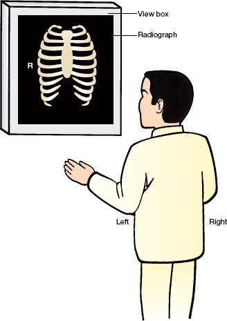
FIGURE 3.1. The correct positioning of a chest radiograph on an image display. The patient’s right side on the film should always be opposite the viewer’s left side.
Table 3.1
Checklist for Frontal Chest Film Review
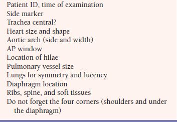
When first reviewing a chest film, we suggest the observer render an initial Gestalt impression by examining the entire image for any obvious abnormality such as an enlarged heart or a lung mass. Then, we suggest reviewing the film in a logical and methodical approach. Checklists reduce human error and they are a feature of everyday life. The use of a mental checklist is essential to avoid overlooking radiographic abnormalities. The following checklist or system is suggested in Table 3.1. We find it useful to start at the top of the film and identify the tracheal air column. This accomplishes two goals: Firstly, the trachea on a correctly centered PA film should be midline and should be superimposed over the spinous processes of the upper thoracic spine, and the scapulae should be clear of the lungs. This ensures that the patient is not rotated (Fig. 3.2). Secondly, any deviation of the trachea off midline on a correctly centered film indicates a potential mediastinal or thyroid mass.
Next, follow the trachea inferiorly to arrive at the cardiac outline, for an evaluation of the heart size. The transverse diameter of the heart should not exceed 50% of the transverse diameter of the thoracic cage measured at the same level. This is called the cardiothoracic ratio (Fig. 3.3). This measurement, however, is only accurate on PA films as there is considerable magnification of the cardiac silhouette on AP projections which makes an accurate determination of heart size on portable films generally unreliable. To illustrate the nature of this magnification, consider the analogy of the shadow cast of your hand by a flashlight; the closer your hand is to the surface/shadow, the more accurate the size of the silhouette. For this reason, PA films are performed with the anterior chest wall closest to the film cassette with the term PA denoting the direction of the x-rays (posterior to anterior). Poor inspiratory effort and recumbency can further exaggerate the cardiac size.
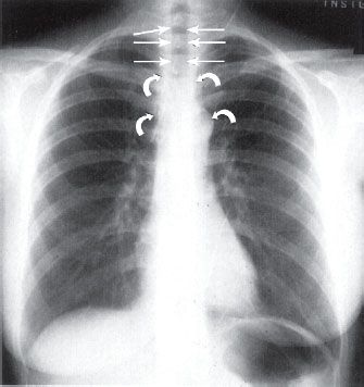
FIGURE 3.2. Normal chest PA radiograph. The vertical trachea (straight arrows) should always be midline. The narrow mediastinum is water density (curved arrows).
Next, evaluate the shape of the cardiac silhouette which has multiple components. The convex right cardiac border is formed by the right atrial shadow, which resides just below the vertical straight border rendered by the superior vena cava (SVC) (Fig. 3.4). The left ventricle constitutes the left heart border and the cardiac apex. The superior left cardiac border should be concave in most cases (Fig. 3.4). The right ventricle is directly superimposed on the cardiac silhouette and is not a border-forming structure on frontal radiographs. Similarly, a normal sized left atrium is also not visible on PA or AP radiographs (Fig. 3.5). In cases of left atrial enlargement, the superior left heart border becomes convex, and in severe cases, the right lateral border of the left atrium may become superimposed over the right atrial shadow, producing what is known as the double-density sign (Fig. 3.6). As the left ventricle enlarges, the cardiac apex moves down and out. As the right atrium enlarges, the right heart border becomes protuberant (Fig. 3.7).
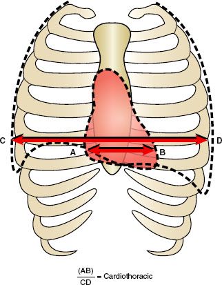
FIGURE 3.3. The cardiothoracic ratio. The CTR is calculated by measuring the transverse diameter of the heart (A–B) and dividing by the transverse thoracic measurement (C–D).
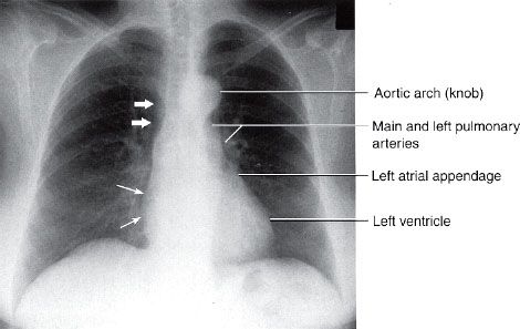
FIGURE 3.4. Normal chest posteroanterior (PA) radiograph. The convex right cardiac border is formed by the right atrium (straight thin arrows), and the heavy arrows indicate the location of the superior vena cava. The left cardiac and great vessels border might be considered as four skiing moguls. From cephalad to caudad the moguls are the aortic arch, the main and left pulmonary arteries, the left atrial appendage, and the left ventricle.
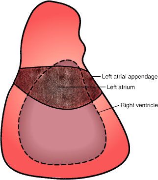
FIGURE 3.5. Cardiac chambers. The approximate location of the left atrium and right ventricle on a normal PA or AP chest radiograph. These cardiac chambers cannot be delineated on normal studies. However, the left atrial appendage can occasionally be seen in normal patients, especially younger females.
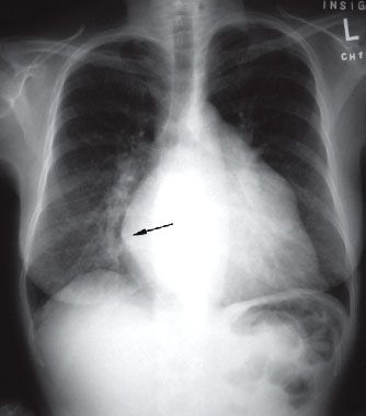
FIGURE 3.6. Left atrial enlargement. PA radiograph. This film shows the double density sign (arrow) produced by the overlapping of the left atrium with the right heart border (right atrium). Also, note the outward convexity of the upper left heart border typically seen with left atrial enlargement.
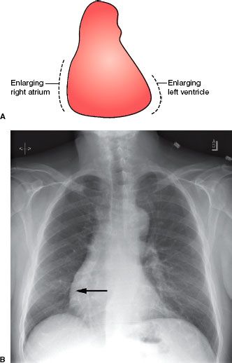
FIGURE 3.7. Right atrial and left ventricular enlargement. Cardiac silhouette changes during right atrium and left ventricle enlargement. A: As the right atrium enlarges, the convex right heart border enlarges to the patient’s right. As the left ventricle enlarges, the cardiac apex moves to the patient’s left and downward. B: PA chest radiograph showing right atrial enlargement (arrow).
Next, your review should take you superiorly to the aortic arch, pulmonary arteries, and the main stem bronchi. The left and right pulmonary arteries and the main stem bronchi form the primary hilar shadows. On normal chest radiographs, the left hilum is higher than the right hilum in approximately 70% of normal chest films and is at the same level in the remaining 30% of cases. A lower left than right hilum should alert one to left lower collapse. The pulmonary arteries and their lobar branches radiate outward from the hila. In an upright person, the pressure differential is enough that the lower lobe pulmonary vessels should be larger than the upper lobe vessels because of greater blood flow. The main pulmonary artery can be prominent in the young and athletic, especially in females. The aortopulmonary window is the concavity or space immediately below the aortic arch and above the left pulmonary artery (Fig. 3.8). Convexity of the aortopulmonary window raises the suspicion of either a mass or adenopathy occupying this space. It is important to remember that in the elderly the thoracic aorta commonly becomes tortuous or ectatic, and this should not be interpreted as abnormal. Now divide the lungs into horizontal thirds and compare the right and left lung fields for symmetry and lucency (Fig. 3.8).
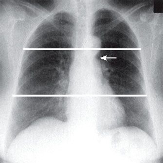
FIGURE 3.8. Normal lung lucency. Chest PA radiograph. Divide the PA or AP chest radiograph into horizontal thirds and compare the right and left lung fields moving in a head to foot direction. Note the aortopulmonary window (arrow).
Next, your attention should be directed to the mediastinum which is the extrapleural space between the lungs, specifically its contour and width. The vascular pedicle extends from the thoracic inlet to the base of the heart caudally. The right border of the pedicle is the SVC, and the left border is the aortic arch near the origin of the left subclavian artery (Figs. 3.2 and 3.9). Next, review both diaphragms; the right hemidiaphragm should normally be about 1 to 2 cm higher than the left due to the liver. The lateral recesses of the diaphragms form the lateral costophrenic gutters, which should be sharp and form an acute angle where the diaphragms insert laterally to the chest wall. Finally, determine the location of the gastric air bubble (if present), which should be underneath the left hemidiaphragm (Fig. 3.10).
The lower cervical spine, thoracic spine, shoulders, and ribs complete a routine review of a chest film (Figs. 3.10 and 3.11). On a PA radiograph, the horizontal portions of each rib are the posterior arcs and the anterior ribs are usually angled downward (Fig. 3.11). Rib abnormalities may be easier to detect by rotating the image 90 degrees (clock- or counterclockwise). Although the bony structures are not very well delineated on chest radiographs, significant abnormalities can be seen, emphasizing the need for review of the four corners of the radiograph (Fig. 3.12).
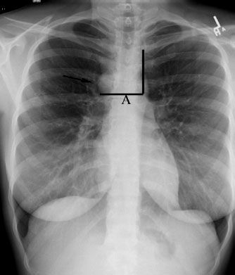
FIGURE 3.9. Normal vascular pedicle. The vascular pedicle is determined by drawing a horizontal line (A) from the junction of the azygos vein (arrow ) and SVC over to a perpendicular line drawn from the left subclavian artery inferiorly along the transverse portion of the thoracic aorta (aortic arch).
Three areas where lung lesions are commonly missed are behind the anterior first ribs, behind the heart, and behind the diaphragm.
Lateral
For lateral radiographs, it is customary to have the film oriented such that the patient is facing toward your left (Fig. 3.13). Once again, begin by reviewing the entire image looking for any obvious abnormalities. Following this, evaluate the size and shape of the cardiac silhouette, which lies anteriorly. On lateral projections, the right ventricle forms the anterior border of the cardiac silhouette. The left ventricle forms the major portion of the inferior–posterior cardiac border, and the left atrium forms the superior–posterior cardiac border. On most lateral chest radiographs, the posterior wall of the inferior vena cava can be seen as it enters from the abdomen into the right atrium (Fig. 3.13, straight arrows). The identification of the inferior vena cava shadow is useful in the determination of left ventricular size. The left ventricle is considered enlarged when the posterior border of the left ventricle resides 2 cm or more posterior to the inferior vena cava. Since the right atrium is a superimposed cardiac chamber, it is not visualized on the lateral projection.
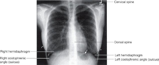
FIGURE 3.10. Normal PA chest radiograph. After comparing the lung fields, you next view the diaphragms, costophrenic angles, and lower dorsal spine. Note the close proximity of the gastric fundus air to the left hemidiaphragm (straight arrow). Always remember to identify both breast shadows in female patients (curved arrows).
The lateral film is the best view to evaluate the hilar structures. By drawing a vertical line down the tracheal air column, both hila can be distinguished (Fig. 3.14). The dominant shadow ventral to your line is largely composed of the right main pulmonary artery, which should be about the size of the distal phalanx of your thumb. The left hilum, composed primarily of the left pulmonary artery, resides posterior to this line and should be about one-third the size of the right. Next, locate the sternum and search the retrosternal and pre-cardiac spaces for abnormal or pathologic soft tissue or air shadows (Fig. 3.15A). On the lateral view, the retrosternal lucency is due to the superimposition of the aerated upper lobes, whereas the right middle lobe and the lingular segment are projected over the cardiac silhouette. The lower lobes are located in the retrocardiac space overlying the spine extending inferiorly to the diaphragms (Fig. 3.15B). It is important to understand the pulmonary lobar spatial relationships in locating pathologic pulmonary processes. The apical segments of the lower lobes extend as high as the fourth thoracic vertebra and the costophrenic recesses of the lower lobes may extend down to the second lumbar vertebra.
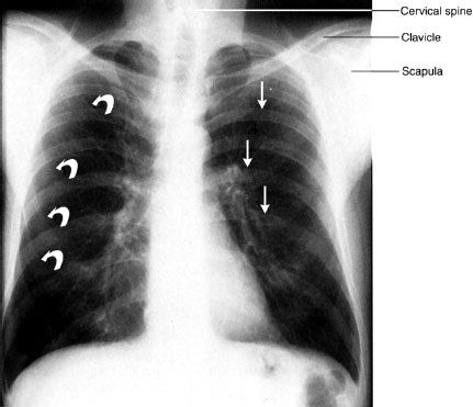
FIGURE 3.11. Normal PA chest radiograph. The posterior ribs (straight arrows) are horizontal and anterior ribs (curved arrows) are angled caudad or inferiorly. All of these structures must be included in your checklist as well as the shoulder girdles and cervical and dorsal spine areas.
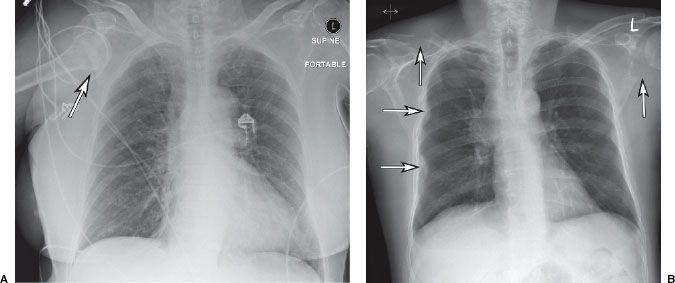
FIGURE 3.12. Do not forget the four corners! A: Anterior dislocation of the right humeral head (arrow). B: Several lytic bony lesions reflecting metastatic disease including the left scapula, right clavicle, and several ribs on the right side (arrows).
Finally, observe the contours of the diaphragms and the posterior costophrenic angles (or gutters). The right hemidiaphragm should be slightly lower in location and more magnified than the left on the lateral view. This is important in identifying and determining the location of a small pleural effusion, which may not be apparent on the frontal film. Note that the right hemidiaphragm can be seen in its entirety, because air in the right lower lobe abuts the soft tissue density hemidiaphragm allowing a sharp interface to be formed. On the left, only the cardiac apex and posterior hemidiaphragm are generally demonstrated, so the anterior aspect of the left diaphragm is usually obscured by its continuity with the heart and pericardial fat (Fig. 3.16).
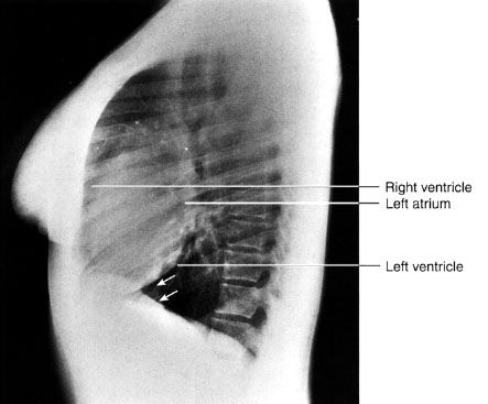
FIGURE 3.13. Normal lateral chest radiograph. The cardiac silhouette makes an excellent starting point for your evaluation. The faint vertical water density line (arrows) represents the inferior vena cava.
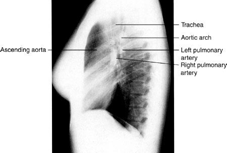
FIGURE 3.14. Normal lateral chest radiograph. The oval-shaped right pulmonary artery lies anterior and inferior relative to the left pulmonary artery. The left pulmonary artery crosses cephalad over the left main stem bronchus and it lies inferior to the aortic arch.
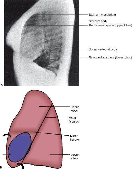
FIGURE 3.15. A: Normal lateral chest radiograph. The anterior and posterior bony structures should always be routinely viewed. The spine appears less dense as you proceed caudally due to attenuation by the shoulders. B: Illustration of the spatial relationships of the pulmonary lobes on the lateral view. Note that the right middle lobe and the lingular segments of the left upper lobe (curved arrows) project over the heart (straight arrow). The lower lobes are primarily posterior structures. The major fissures extend obliquely up to approximately the T4 level.
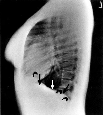
FIGURE 3.16. Normal lateral radiograph. Note that the left hemidiaphragm (straight arrows) is not visible anteriorly where it abuts the heart (water density). This is an excellent example of the silhouette sign. On the other hand, the entire right hemidiaphragm (curved arrows) is visible.
Additional Views
The AP lordotic view, which is an AP film taken with the patient leaning back is useful for visualization of upper lobe or apical pathology (Fig. 3.17). This projection displaces the clavicles above the thoracic inlet and enables better visualization of the lung apices.

FIGURE 3.17. Apicolordotic view. This view is obtained with the patient leaning backward. Note how the clavicles project above the lung apices allowing better visualization of the upper lobes. This film shows a cavitary lesion in the right upper lobe (arrow) due to an atypical mycobacterial infection.
Placing a patient on their side (decubitus position) and obtaining a film across the chest in the AP direction is described as a decubitus view. This view is helpful for detecting small amounts of pleural air or fluid, which may not be seen on the standard views described above (Fig. 3.18).
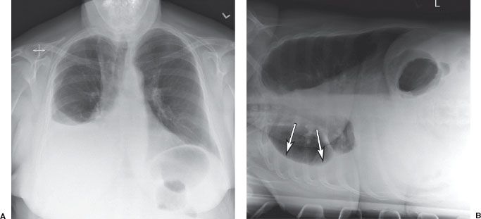
FIGURE 3.18. Right pleural effusion. A: PA chest film shows a moderate right pleural effusion. B: Right lateral decubitus film confirms that the right pleural effusion (arrows) is free flowing and not loculated.
NORMAL THORACIC CROSS-SECTIONAL ANATOMY
Multidetector (or spiral) CT (MDCT) allows imaging of the chest within one breath hold (~15 seconds or less). Figures 3.19 to 3.27 demonstrate normal cadaveric cross-sectional anatomy correlated with CT and magnetic resonance (MR). In general, CT is preferred to MR for chest and pulmonary imaging because of faster examination times and less susceptibility to motion and respiratory artifacts. Some MDCT scanners are capable of scanning the heart in a heartbeat, with excellent spatial and temporal resolution allowing three-dimensional (3D) visualization of the coronary arteries (Fig. 3.28).
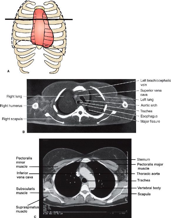
FIGURE 3.19. Normal axial cross-sectional anatomy. A: Approximate axial anatomic level through the aortic arch for (B) and (C). B: Axial cadaver radiograph of the sectioned chest at the aortic arch level. Normal. A frozen cadaver was sectioned and then radiographed. C: Normal chest CT image at the aortic arch level with mediastinal windows.
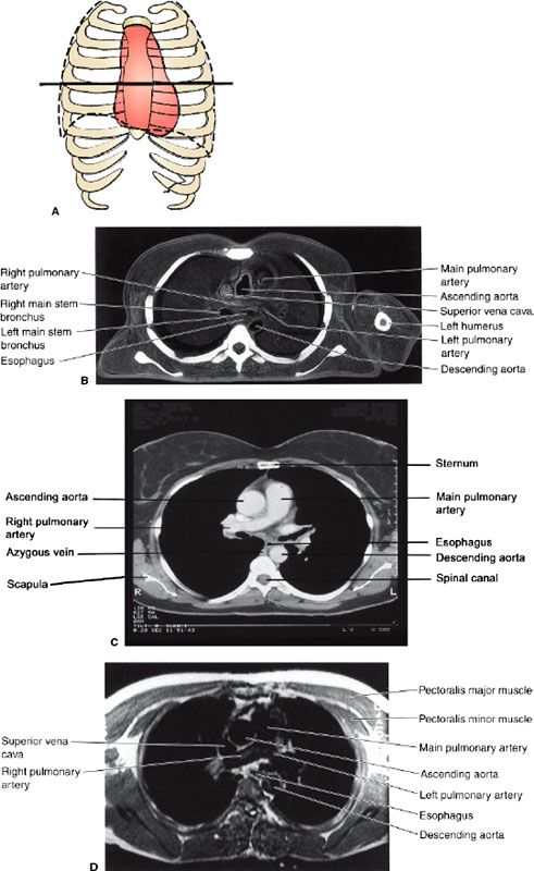
FIGURE 3.20. Normal cross-sectional anatomy. A: Approximate axial anatomic level through the pulmonary arteries for (B–D). B: Axial cadaver radiograph of the sectioned chest at the level of the pulmonary arteries. C: Chest axial CT images at the level of the pulmonary arteries in mediastinal windows. D: Chest axial MR image at the level of the pulmonary arteries.
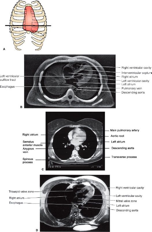
FIGURE 3.21. Normal cross-sectional anatomy. A: Approximate axial anatomic level through the right and left atria for (B–D). B: Axial cadaver radiograph of the sectioned chest at the level of the right and left atria. C: Chest axial CT images at the level of the atria in mediastinal windows. D: Chest axial MR image at the level of the atria.
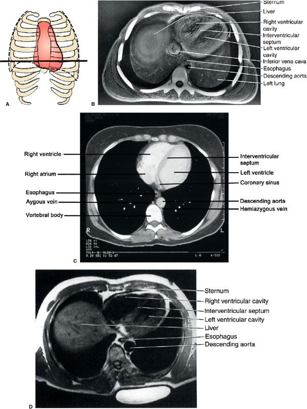
FIGURE 3.22. Normal cross-sectional anatomy. A: Approximate axial anatomic level through the right and left ventricles for (B–D). B: Axial cadaver radiograph of the sectioned chest at the level of the ventricles. C: Chest axial CT image through using a mediastinal window. Normal. D: Chest axial MR image at the level of the ventricles.
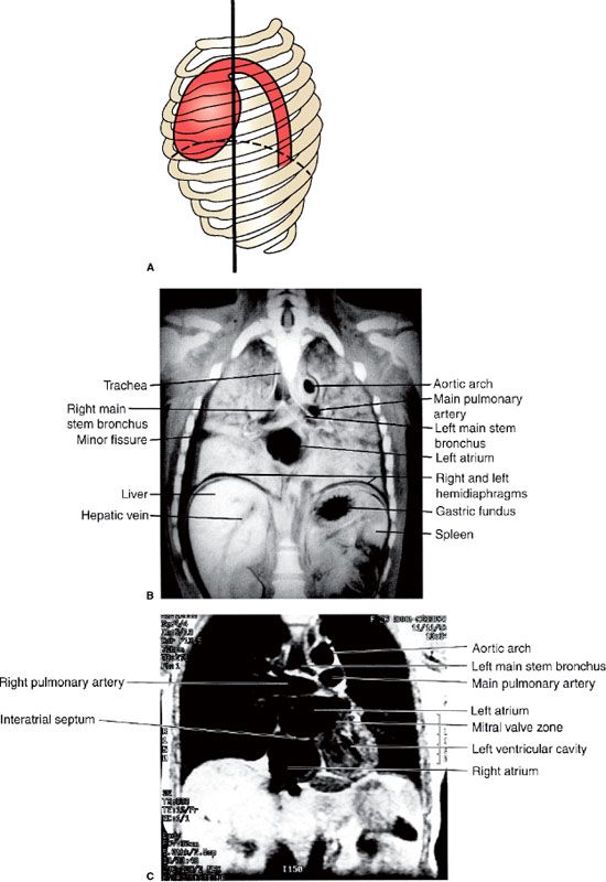
FIGURE 3.23. Normal coronal sectional anatomy. A: Illustration of the approximate coronal anatomic level through the left atrium for (B) and (C). B: Coronal cadaver radiograph of the sectioned chest through the level of the left atrium. Normal. C: Chest coronal MR image through the right and left atria.

FIGURE 3.24. Normal coronal sectional anatomy. A: Approximate coronal anatomic level through the right atrium and left ventricle for (B) and (C). B: Coronal cadaver radiograph of the sectioned chest through the level of the right atrium and left ventricle. C: Chest coronal MR image through the atria and left ventricle.
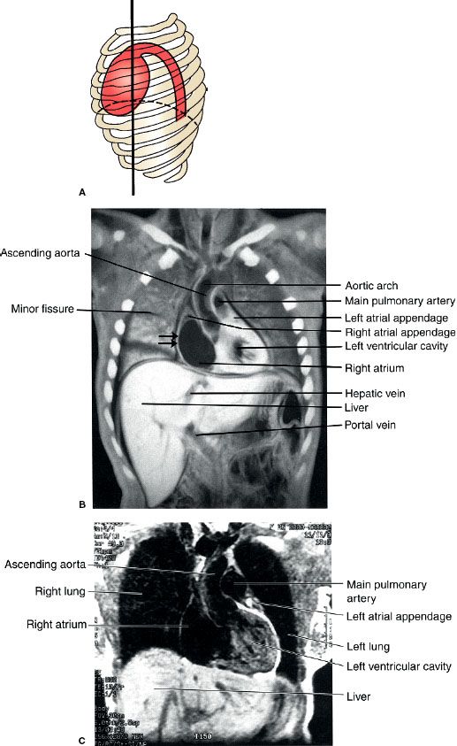
FIGURE 3.25. Normal coronal sectional anatomy. A: Illustration of the approximate coronal anatomic level through the left ventricle and the ascending aorta for (B) and (C). B: Coronal cadaver radiograph of the sectioned chest through the left ventricle and the ascending aorta. Note that the convex right cardiac border is due to the right atrium (straight arrows). C: Chest coronal MR image through the left ventricle and the ascending aorta.
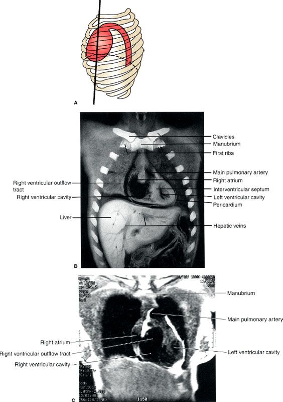
FIGURE 3.26. Normal coronal sectional anatomy. A: Illustration of the approximate coronal anatomic level through the ventricles for (B) and (C). B: Coronal cadaver radiograph of the sectioned chest through the ventricles. Normal. C: Chest coronal MR image through the ventricles.
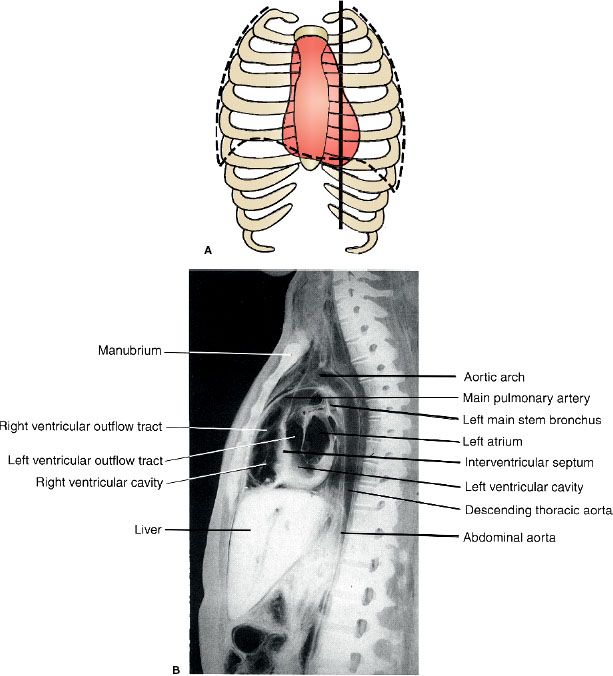
FIGURE 3.27. Normal sagittal anatomy. A: An illustration of the approximate sagittal anatomic level for (B). B: Sagittal cadaver radiograph of the sectioned chest through the right ventricular outflow tract and the right ventricle.
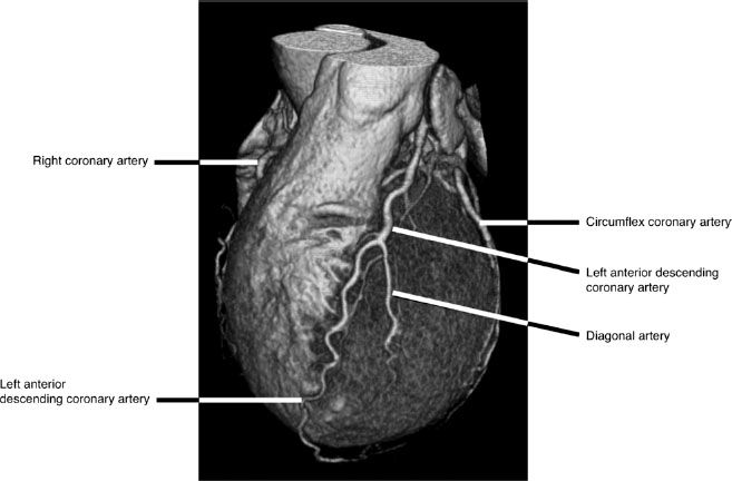
FIGURE 3.28. CTA surface rendered volumetric image of the left coronary circulation provides a 3D perspective and demonstrate the left coronary arteries relative to underlying cardiac structures. The left anterior descending coronary artery supplies most of the left ventricle while the circumflex artery runs in the left atrio-ventricular groove. A portion of the right coronary artery is visible along the left side of the image.
CONGENITAL VASCULAR ANOMALIES
Embryonic migration of the azygos vein up over the superior recess of the right upper lobe creates a mock vertical fissure-like opacity (Fig. 3.29) which is created by indentation of both visceral and parietal pleural surfaces along the arc-like course of the azygos vein as it courses inferiorly to insert normally into the SVC. This azygos fissure, which is only visualized on PA radiographs as a thin curvilinear line and outlines an azygos lobe is a common normal variant and is of no clinical significance.
The most common thoracic aortic anomaly is a right-sided aortic arch (Fig. 3.30). On the PA radiograph, the right-sided arch often appears more cephalad than a normal left-sided arch. The most common types are right-sided aortic arch with aberrant left subclavian artery and the mirror-image type. The variant with aberrant left subclavian artery is rarely associated with congenital heart disease whereas the mirror-image type of right aortic arch is very strongly associated with congenital heart disease, most commonly tetralogy of Fallot.
Coarctation of the aorta is a focal stenosis at the junction of the aortic arch and the descending thoracic aorta. The degree of coarctation is variable, and the clinical features vary with the location and degree of stenosis. Patients may have a systolic murmur, cardiac enlargement, and pre- and poststenotic aortic dilatation depending on the location and severity of the stenosis (Fig. 3.31). Rib notching can occur along the inferior aspect of the ribs reflecting collateral blood flow through dilated intercostal arteries (Fig. 3.31B).
FIGURE 3.29. Azygos lobe. Chest PA radiograph. The azygos lobe is outlined with a white arrow. Also note the areas of discoid atelectasis in the lower lobes (black arrows) in the basilar regions of both lungs.
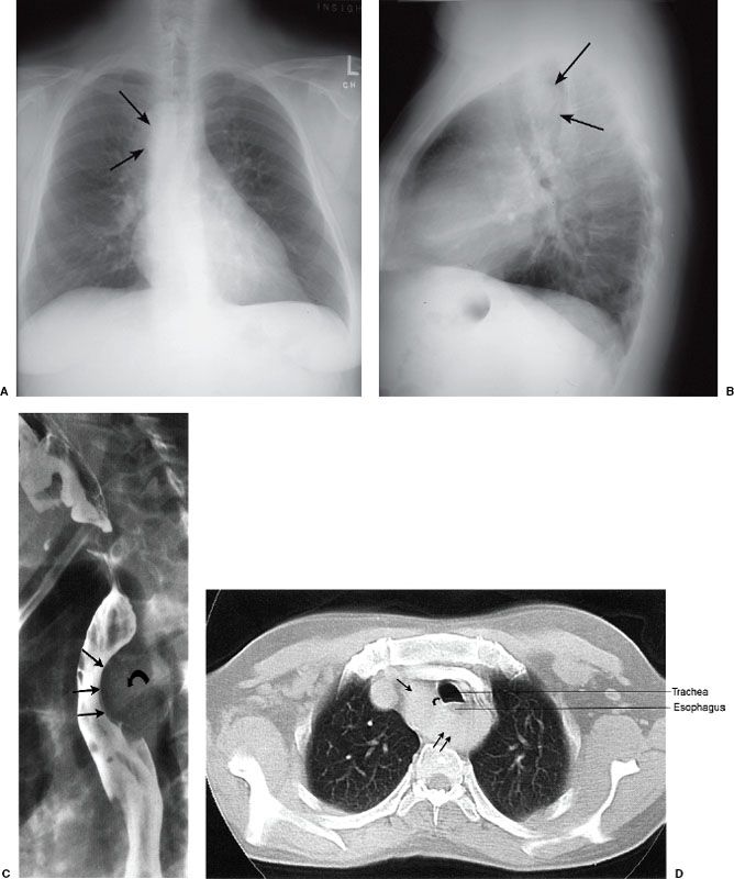
FIGURE 3.30. Right-sided aortic arch and left descending thoracic aorta. Chest PA (A) and lateral (B) radiographs, barium swallow (C), and chest CT (D). This 42-year-old male smoker was suspected of having cancer of the lung. A: A neoplastic mass was suspected on the PA radiograph, but this proved to be an ill-defined aortic knob to the right of the midline (arrows). The right aortic arch is indenting the right side of the trachea. B: The right-sided aortic arch indents the posterior aspect of the trachea (arrows) on the lateral radiograph. C: Barium swallow confirms a significant indentation on the posterior aspect of the barium-filled esophagus (straight arrows) secondary to the crossing aortic arch (curved arrow). D: The diagnosis is confirmed by chest CT that shows the right-sided aorta (single straight arrow) passing posterior to the esophagus and trachea (double straight arrows) to reach the left side of the thorax. Again, note the indentation on the right side of the trachea (curved arrow) secondary to the right-sided aortic arch.
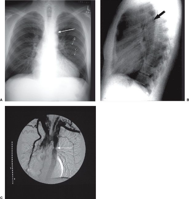
FIGURE 3.31. Coarctation of the aorta. The classical radiographic appearance is an indentation (arrow, A) involving the lateral aspect of the proximal descending aorta on PA radiograph, and a posterior indentation (arrow, B) involving the posterior aspect of the proximal descending aorta on the lateral radiograph. These indentations represent the site of coarctation in the proximal descending aorta. Rib notching (small arrows, A) is also evident along the inferior margins of several ribs. This notching represents collateral blood flow through dilated intercostal arteries. C: Aortic angiogram shows the classic appearance of coarctation (arrow).
FOREIGN BODIES, LINES, AND TUBES
Occasionally objects on the skin may be mistaken for chest pathology. Examples included are hair braids and skin nodules (Figs. 3.32–3.35). Characteristically these are very well defined on the chest radiograph. An innocuous skin fold which appears as a well-defined line traversing the lung may be mistaken for the visceral pleural edge of a pneumothorax. Some foreign bodies such as central venous lines and endotracheal and nasogastric tubes are intentionally placed (Fig. 3.36) and it is important to recognize and document the course and location of these when caring for acutely ill patients. The optimal location of central venous lines is between the mid SVC and the mid right atrium. The optimal location for the tip of an endotracheal tube is 5 cm above the carina.
Air in the Wrong Places
A pneumothorax is an accumulation of air within the pleural space. It is most often spontaneous or may be due to trauma or iatrogenic causes such as lung biopsy (Table 3.2). The definitive radiographic diagnosis of pneumothorax is made by identifying the visceral pleura edge of the collapsed lung (Fig. 3.37). Additional findings include an abnormally hyperlucent hemithorax and loss of peripheral lung markings on the affected side. Upright or decubitus films are useful ways to document the presence of pleural air. Expiratory films accentuate air trapping in the pleural space and may make small and subtle pneumothoraces more visible. Recumbent portable films on the other hand are unreliable for demonstrating even large pneumothoraces, because the air resides immediately ventral to the lung and is not visualized on a frontal view. A tension pneumothorax occurs when the air within the pleural space is sufficiently large to produce mass effect upon the mediastinal structures and ipsilateral diaphragm. If sufficiently great enough, the mass effect on the heart and great vessels can produce acute cardiovascular collapse due to diminished cardiac output (Fig. 3.38). A tension pneumothorax represents an emergency requiring immediate placement of chest tube to decompress the pleural space. For most pneumothoraces, the optimal location for chest tube placement is the second intercostal space in the mid clavicular line. Most pleural effusions are percutaneously drained (thoracentesis) posteriorly below the seventh intercostal space.
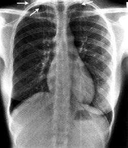
FIGURE 3.32. Hair braid. A soft tissue shadow (arrows) projects over the right supraclavicular region.
Related posts:
Stay updated, free articles. Join our Telegram channel

Full access? Get Clinical Tree


