Introduction
Three-dimensional (3D) printed anatomic models and guides designed from volumetric medical imaging data are used clinically to provide increased comprehension of anatomy, more exact pathology evaluation, and more precise surgical intervention. Historically, obtaining a 3D printed patient-specific anatomic model was typically made possible through independent companies, several of which began building anatomic models for surgeons in the early to mid-1990s. Today, a variety of third party companies provide services in which they accept medical imaging data and produce high quality 3D printed anatomic models. However, in order to bring 3D printing closer to the patient, decrease costs, and expedite the time required to get patient-specific 3D printed models and guides, many hospitals in the United States (US) and world are building 3D printing labs to provide this service in-house, in real time, and in response to trauma and other time-sensitive procedures. , From 2010 to 2016, the number of hospitals in the US with a centralized 3D printing laboratory grew from 3 to 99. , As of July 2019, at least 268 hospitals worldwide have adopted this innovative approach to patient care. , Given the consistent growth in production of 3D printed anatomic models and guides at the point of care over the last decade, continued growth is expected. Through the use of illustrative case examples, this chapter provides readers with a detailed understanding of this advanced application of 3D printing technology in today’s medical practice.
Anatomic Models
3D printed anatomic models offer a tangible extension of medical imaging that can be understood by a diverse audience quickly and easily. An anatomic model can help physicians communicate with their patients with a high level of clarity and understanding; two-dimensional (2D) imaging on a flat screen cannot compete. Trying to explain imaging findings with 2D imaging to patients who may not have in-depth knowledge of cross-sectional anatomy may prove challenging. By isolating individual anatomies, implanted devices, and pathologies, radiologists are able to relay spatial relationships of internal anatomical components that are otherwise difficult to view.
Anatomic models are built from 3D meshes of anatomy generated through the segmentation of medical imaging data and subsequent computer-aided design (CAD) modeling. , First, Digital Imaging and Communication in Medicine (DICOM) images are acquired from any imaging modality with volumetric imaging capability. Commonly used modalities include computed tomography (CT), magnetic resonance imaging (MRI), or ultrasound. High spatial resolution images with low signal-to-noise ratio and thin slice thicknesses are preferred. Once imaging is selected, segmentation is performed via placement of regions of interest (ROIs) around the desired tissues. Various dedicated software packages are available for the segmentation of 3D medical images, and the segmentation of appropriate ROIs can be obtained automatically using algorithms such as thresholding, edge detection, and region growing, or manually (see Chapter 3). Segmentation times range substantially and will depend on the imaging quality, use of automated techniques, and user’s experience level. Segmented ROIs are then converted to a CAD file format such as the commonly used stereolithography (STL) format for editing and exportation to facilitate recognition by 3D printing software. The STL format is currently the most common file type and it is used in all cases in this chapter.
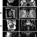
Before printing, STL files are verified to ensure anatomical accuracy through a defined quality assurance plan, and then imported to the designated 3D printing software. , The model is oriented to minimize printing time and optimize final part material properties, and printing materials are selected based on provider needs, printer specifications, and anatomic tissue type. Next, STL files are sent to the printer, and the 3D model is printed. Printing times vary depending on printer type, printing layer height and resolution, number of materials, and size of the object. Finally, post-processing is performed to remove support material and to enhance the appearance of the printed item. As this process of converting DICOM data to STL format is unfamiliar to many radiologists, a typical workflow is demonstrated in Table 6.1 . , ,
| 1. Image Acquisition | 2. Image Segmentation | 3. CAD Modeling | 4. 3D Printing |
|---|---|---|---|
|
|
|
|
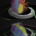
Fig. 6.1 illustrates the creation of a life-sized model of a thoracic cavity tumor surrounded by important structures including the ribs and sternum, cartilage, lungs, cardiac structures, aorta, and superior and inferior vena cava. This type of model can help to quickly bring a surgical team up to speed on how the tumor is entangled in otherwise healthy tissue and can help to form a communication bridge between radiologist, surgeon, operating room (OR) team, and patient. When printed in tissue mimicking materials, anatomic models such as this can also facilitate the rehearsal and practice of complex procedures on a patient’s specific anatomy prior to entering the OR.

Simple Anatomic Models
Anatomic models are all derived from some variety of medical imaging, and radiology plays in integral role in model generation. Whether they are simple single-part or complex multimodality models, 3D printed anatomic models can be used as powerful communication tools between surgeon and patient, surgeon and care team, and surgeon and pathologist. Two use cases are shown to illustrate the clinical need behind the creation of a simple anatomic model. To generalize, a simple model is created from one data series from one imaging study and does not require advanced manipulation of data, e.g., coregistration of multiple imaging modalities or use of advanced CAD tools. Development and design of a simple model may require less time, but time required is still affected by quality of imaging and complexity of ROI. Simple models are held to the same high standard of quality assurance as complex models. ,
Case 1
An orthopedic surgeon prepared to treat a 67-year-old male with a massive rotator cuff tear and osteoarthritis of the right shoulder with a reverse total shoulder arthroplasty, a procedure in which implants are used to turn the proximal humerus into the socket and the scapular glenoid into the ball of the joint. Day one of patient care included CT imaging and surgical consultation; surgery was planned for day four, so segmentation, CAD, printing, cleaning, and post-processing all took place within a 48 h period. The orthopedic surgeon requested 3D printed models of the humerus and scapula to rehearse the procedure and reference during the operation. Since bone is best depicted on CT and no vasculature was requested, the imaging series selected was a soft-tissue reconstruction kernel with 2.0 mm slice thickness and no intravenous contrast. Choosing the soft-tissue kernel as opposed to the sharp for bone segmentation may seem counterintuitive, but the soft-tissue series is superior for medical imaging segmentation due to the noise that can occur in a sharp-kernel reconstruction, which translates to the mesh surfaces. The humerus and scapula were segmented and initial ROI contours were reviewed by a radiologist. In the CAD environment, the 3D meshes of the bones were run through a smoothing algorithm with appropriate parameters so as to not alter the overall surface contours of the parts. The humerus and scapula were stamped with an accession number from the original modeling order for traceability, and contours of the final STLs were reviewed over the imaging to confirm anatomical accuracy. The 3D printing technology was selected in accordance with the surgeon’s needs. In this case, a ProJet CJP 660Pro (3D Systems, Rock Hill, SC) binder jetting printer was selected. Since this technology allows input files with color, both parts were assigned Pantone’s “Bone” RGB values and exported as ZPR files for input to the ProJet CJP 660Pro. The files were printed and the final parts were infiltrated in paraffin wax to best simulate the feel of bone in accordance with the surgeon’s preference ( Fig. 6.2 ).

Case 2
A vascular surgeon prepared to treat a 41-year-old female with a Type A aortic dissection in the arch and right subclavian arteries and engulfing the ascending aorta. Treatment options, including the endovascular placement of a commercial stent, were being evaluated and a model of the true and false lumens was requested. In order to properly segment the blood pool and capture the false lumen wall, a high quality contrast-enhanced CT was selected, and a series with 2.0 mm slice thickness and a soft-tissue reconstruction kernel was selected. The true and false lumens were segmented as separate parts and calculated into 3D meshes, smoothed, and the descending aorta was trimmed just inferior to the heart. To best visualize the dissection, the model was printed with material jetting on an Objet500 Connex3 printer (Stratasys, Eden Prairie, MN). When loading the STLs into the printing software as an assembly, the true lumen was assigned a semiclear material and the false lumen was assigned an opaque magenta. To maximize the transparency of the true lumen, the model was clear-coated after support material was removal via water jetting. The final model worked to illustrate the extent of the false lumen within the true lumen ( Fig. 6.3 ).

Complex Anatomic Models
Complex anatomic models can include more than one bone or anatomic part, and are often derived from a number of data series. In many cases, coregistration of either imaging data from multiple series or even modalities is required. Coregistration is also commonly performed on 3D parts from a variety of series data, where bone is often the fixed entity and all other elements align. Complex models may also include anatomy that has been significantly altered or manipulated from the “as-scanned” state to further facilitate surgical planning or other intervention. Examples include mirroring anatomy, resecting or reconstructing anatomy, or designing grafts. , Developing a complex anatomic model with multiple parts follows a similar workflow as described for a simple anatomic model. The imaging series is selected, segmentation takes place, CAD modeling follows, contour review is performed, and the model is 3D printed. Several use cases for complex anatomic models are described below.
Case 1
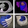
An orthopedic surgeon prepared to treat a 26-year-old female with a right posterior pelvic osteosarcoma tumor and a complex venous malformation. In this case, the surgeon requested a pelvic tumor model which included bone, veins, arteries, ureters, bladder, and tumor to assist with surgical planning of tumor resection amidst the dangerous vascular malformation. Therefore, imaging that allowed for reasonable segmentation of each requested anatomic element was required. A triphase contrast-enhanced CT study was selected as it was the optimal choice with arterial, venous, and urogram phases. All three reconstructions were done with a soft-tissue kernel and had slice thicknesses of 2.0 mm. Each of the three phase series was segmented accordingly: the arterial phase was used to segment bone and arteries, the venous phase was used to segment veins, and the urogram phase was used to segment the ureters and bladder. Since a triphase study is collected sequentially as the contrast moves through the circulatory system, either the imaging series themselves or the corresponding segmented parts needed to be coregistered to one primary series to account for differences in timing and motion. In this case, the primary series selected was the arterial phase as it was used to segment bone, and the parts segmented from the venous and urogram phases were coregistered using N-point registration of the pelvic bone and accompanying anatomic elements. Additional CAD modeling was necessary to ensure that each part remained in its proper anatomical position after 3D printing. Thin cylinders were added as struts to strengthen the model at specific weak points, e.g., the venous malformation on the patient’s right side was connected to the bone. This case was built on a material jetting printer (Objet500 Connex3, Stratasys, Eden Prairie, MN) with the bone in a clear material to allow for visualization of the intrusion of the tumor (dark purple) along with the other pertinent anatomical structures ( Fig. 6.4 ).

Case 2
An ear, nose, and throat surgeon prepared to treat a 19-year-old male with a left lymphovascular tumor and vascular malformation. The model was requested to aid in surgical planning and discussion of options with the care team, and the extent of the tumor and vascular malformation were of high importance. To properly segment both the tumor and the vascular malformation in addition to the bone and detail of the orthodontia hardware, a noncontrast soft-tissue reconstruction kernel CT image series with a slice thickness of 0.6 mm was selected. Maxilla, mandible, hardware, vascular malformation, and tumor were segmented from this series. An important element of the model was to visualize bone interacting with tumor, which could require a multimaterial printer with clear material loaded, as shown in Complex Case 1. Alternatively, in this case, the surfaces of the vascular malformation and tumor meshes were converted to lattices as illustrated in Fig. 6.5 . This is a highly technical CAD operation, and works well to provide transparency on a single-material printer. This model was printed on a powder bed fusion printer (HP Jet Fusion 580 Color, HP, Palo Alto, CA).

Case 3
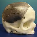
An orthopedic surgeon prepared to treat a 28-year-old female with rapidly progressive thoracolumbar spinal deformity and dural ectasia (DE). Medical history included a spinal fusion at age 5, which is the source of the hardware shown in the models. In order to best visualize the remaining native spine and hardware, the bone, the DE, and hardware were segmented from a noncontrast soft-tissue reconstruction kernel CT series with 0.75 mm slices. Two models with different goals were 3D printed. In the first model, bone, including a short distance of ribs and sacrum, was printed in white with hardware in blue. A second model was developed specifically to show the extent of the DE in the thoracic and lumbar spine, so bone was printed in a clear material, the DE in a clear/blue, and the hardware in blue. The bone in the second model was trimmed to decrease print time. Both models were printed with material jetting on an Objet500 Connex3 printer (Stratasys, Eden Prairie, MN) and the second model was clear-coated after support material removal ( Fig. 6.6 ).

Related posts:
 An Abbreviated History of Medical 3D Printing
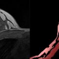 Image Segmentation and Nonuniformity Correction Methods
 Regulatory Perspectives for 3D Printing in Hospitals
 3D Printing in Nuclear Medicine and Radiation Therapy
 3D Printed Imaging Phantoms
 Medical Imaging Technologies and Imaging Considerations for 3D Printed Anatomic Models
Stay updated, free articles. Join our Telegram channel

Full access? Get Clinical Tree


