Introduction
To reproducibly and precisely characterize the ability of a medical imaging system to safely produce accurate images, it is useful to image objects which have properties similar to human tissues for the imaging method being tested, have geometries and compositions that are known exactly, and can remain in an exact location in the imaging system for indefinite periods of time. For this purpose, imaging phantoms are produced for every method (or modality) of medical imaging.
Today, imaging phantoms typically consist of materials (liquids, gels, semisolids, and/or solids depending on the tissue being mimicked and the imaging modality being evaluated) with desired properties and known geometries arranged in glass or plastic containers, sometimes also with glass or plastic inclusions of known dimensions. A variety of phantoms made with a range of shapes, purposes, and methods are commercially available; however, these phantoms are typically costly and often feature simplified geometries. Many applications may require customizable and anatomically realistic configurations, which are not typically achievable with traditional manufacturing technologies. For reference, Table 14.1 includes a number of vendors and links to sites displaying medical imaging phantoms designed for a wide range of purposes.
| Manufacturer | Website | Modalities |
|---|---|---|
| Biodex Medical Systems | https://www.biodex.com/nuclear-medicine/products/phantoms |
|
| Carville Limited | https://www.carvilleplastics.com/products/imaging-phantoms/ |
|
| Computerized Imaging Reference Systems, Inc. (CIRS) | https://www.cirsinc.com/products/ |
|
| Gold Standard Phantoms | https://www.goldstandardphantoms.com/ |
|
| Kyoto Kagaku | https://www.kyotokagaku.com/ |
|
| Leeds Test Objects | https://www.leedstestobjects.com/# |
|
| Modus Medical Devices | https://modusqa.com/ |
|
| PTW Freiburg | https://www.ptwdosimetry.com/en/ |
|
| Radcal Corporation | https://radcal.com/ |
|
| Radiology Support Devices, Inc. | http://rsdphantoms.com/ |
|
Three-dimensional (3D) printing promises new methods and possibilities for the production of medical imaging phantoms, ranging from rapid and accurate production of new designs through accurate reproduction of complex, anatomical shapes based on data from medical images. The number of works incorporating 3D printing in the production of phantoms is growing rapidly. Consequently, it is difficult to give a comprehensive review, and so we rather present an introduction highlighting the variety of materials and approaches with reference to numerous examples. Here, after a brief discussion of material properties pertinent to each major medical imaging modality, we introduce a variety of methods demonstrated to date for all major medical imaging modalities, arranged according to the role of the 3D printed material in phantom production.
Material Properties Pertinent to Major Medical Imaging Modalities
In all forms of medical imaging, some form of energy or matter is administered to the human body. For medically useful information to be produced, tissues must respond differently to the energy or matter applied.
In planar X-ray imaging, computed tomography (CT), magnetic resonance imaging (MRI), and ultrasound imaging, energies of various types are applied to all tissues in the region of interest, and after tissue-specific interactions through space and time, the detected energy has a signature which can be used to map tissue characteristics based on location. For single-photon emission computed tomography (SPECT) and positron emission tomography (PET), radioactive chemicals (or radiotracers) are introduced into the body, accumulating to different degrees in different regions depending on the tissue-specific affinity to the chemical introduced. High-energy photons resulting from radioactive decay (SPECT) or interaction of an emitted positron with a nearby electron (PET) pass through the body to external detectors so that a map of the distribution of the source radiotracers can be generated. Though not desired, these photons may interact with tissue on their way out of the body, which can adversely affect the data acquisition and final image. Generally, phantoms for SPECT and PET are not designed to mimic the accumulation of radiotracer in different tissues but to characterize the ability to accurately quantify the concentration of radiotracer throughout space despite both (1) limitations in system resolution and accuracy (due to a combination of system limitations and the random nature of radioactive decay) and (2) alterations in detected energy due to interactions with matter it passes through.
X-ray imaging, CT, PET, and SPECT all rely on detection of high-energy photons after they pass through all or part of the body. These photons may be scattered or absorbed in various interactions with objects (primarily electrons) in matter they pass through, resulting in an attenuation of the signal intensity. For this reason, electron density is a key characteristic of materials meant to mimic tissues in these modalities. However, how a photon interacts with a given electron depends on the energy of the photon and the affinity of the given electron to its associated nucleus. Therefore, a material with a composition designed to mimic a particular tissue for mammography (breast imaging), where photon energies are low (~20 keV), might not mimic the same tissue well for CT, where photon energies are typically above 100 keV, and would likely mimic that same tissue even less well for PET, which relies on source photons with an energy of 511 keV. To be clear, X-rays (used in X-ray imaging and CT) and gamma rays (used in SPECT and PET) all consist of high-energy photons, with X-rays for medical purposes being produced by an X-ray tube and gamma rays being a product of radioactive decay of an unstable nuclear isotope. The rate of attenuation through tissue (μ) relates directly to the “radiopacity” of the tissue, which is most commonly characterized on a scale relative to the values for air and water, resulting in “Hounsfield units” (HU) ranging from −1000 for air, 0 for pure water, to (approximately) 1000 for bone.
In ultrasound imaging, a beam of acoustic waves generated in a multielement piezoelectric transducer is steered through the tissue and the waves reflected back to the transducer are detected and translated into an image based on the time the reflection was detected in each element of the transducer. For ultrasound, key material characteristics include density, stiffness (related to speed of sound in a given material), backscattering, and attenuation (μ us , related to both backscattering and absorption in a given material). Together, these material characteristics will affect the propagation speed of the sound waves within the tissues (with the speed being higher in tissues such as bone with increased density and stiffness), and how bright a tissue appears in an image (with tissues having greater backscattering appearing brighter). In addition to backscattering of a given tissue, reflections are produced at interfaces between materials of different stiffnesses. For this reason, most energy is reflected at the interface between soft tissue and bone and it is difficult to see beyond these interfaces. In diagnostic medical ultrasound, frequencies from 3 to 10 MHz are most commonly used, and the ability of a given material to mimic a given tissue depends to some degree on the specific frequency used.
In MRI, three different magnetic fields are applied in any number of strategic sequences through time to interrogate tissues as to their spatial density, rate of return to resting state (T 1 relaxation or spin–lattice relaxation rate), and rate of signal decay (T 2 or spin–spin relaxation rate). By far, the most common nucleus used is that of hydrogen (a single proton), though it is possible to interrogate other nuclei as well. Importantly, the human body itself can alter the distribution of the applied magnetic fields and affect the images. In particular, the static magnetic field (B 0 ) is altered by the distribution of magnetic susceptibility (χ m ) through tissue, and the radiofrequency magnetic field (B 1 ) is altered by both tissue electric permittivity and tissue electric conductivity. Importantly, the B 1 field can induce electrical currents in the body that result in unintended heating of tissues. While phantoms can be designed to represent distortions of the fields caused by the human body and even resultant heating, in MRI the tissue properties that are more pertinent to signal and contrast between tissues are proton density (ρ), T 1 , and T 2 . Except for ρ and χ m , all of these properties listed above are dependent on B 0 . Therefore, pha ntom properties must be matched according to tissue properties for given B 0 , which ranges from about 0.5 to 7 T for diagnostic systems.
Due to the time-dependent nature of sequences, physiological processes (including blood flow, perfusion, respiration, and variations in metabolic rate) and physical phenomena (such as diffusion) can also be characterized with medical imaging, and phantoms can be designed to represent these time-dependent characteristics as well. In this chapter, we will focus primarily on phantom material properties with only brief allusion to approaches to simulate physiology in phantoms. Also, while we limit this table to physical interaction as described above, it is also possible to design phantoms to mimic tissues in many other physical properties pertinent to medical imaging, such as directional diffusion for MRI.
Table 14.2 contains a summary of material properties and ranges of photon energy, field strength, or frequency (depending on the modality) relevant to each modality.
| Modality | Detected Energy | Pertinent Material Properties |
|---|---|---|
| Planar X-ray imaging | Photons with energies 15–140 keV | Attenuation μ (scattering, absorption) |
| CT | Photons with energies 100–140 keV | Attenuation μ (scattering, absorption) |
| SPECT | Photons with energies 140–364 keV | Attenuation μ (scattering, absorption) |
| PET | 511 keV photons | Attenuation μ (scattering, absorption) |
| Ultrasound | Ultrasonic vibrations at frequencies 3–10 MHz | Stiffness (speed of sound), backscattering, and attenuation μ us |
| MRI | Radiofrequency magnetic field with frequencies 20–300 MHz (corresponding to B 0 field strengths 0.5 to 7 T) | Proton density ρ, T 1, and T 2 relaxation rates, magnetic susceptibility χ m , electric permittivity, electric conductivity |
Imaging Phantoms with Conventional Materials in 3D Printed Containers
Due to decades of research into tissue-mimicking materials for creating imaging phantoms with a wide range of purposes and, in contrast, the relatively limited range of materials currently available as media for 3D printing, an obvious first step to producing useful imaging phantoms with 3D printing is to print containers (and inclusions) to hold (and displace) conventional materials already known to effectively mimic tissues in the configuration desired. Two very different examples from the literature are shown in Figs. 14.1 and 14.2 .
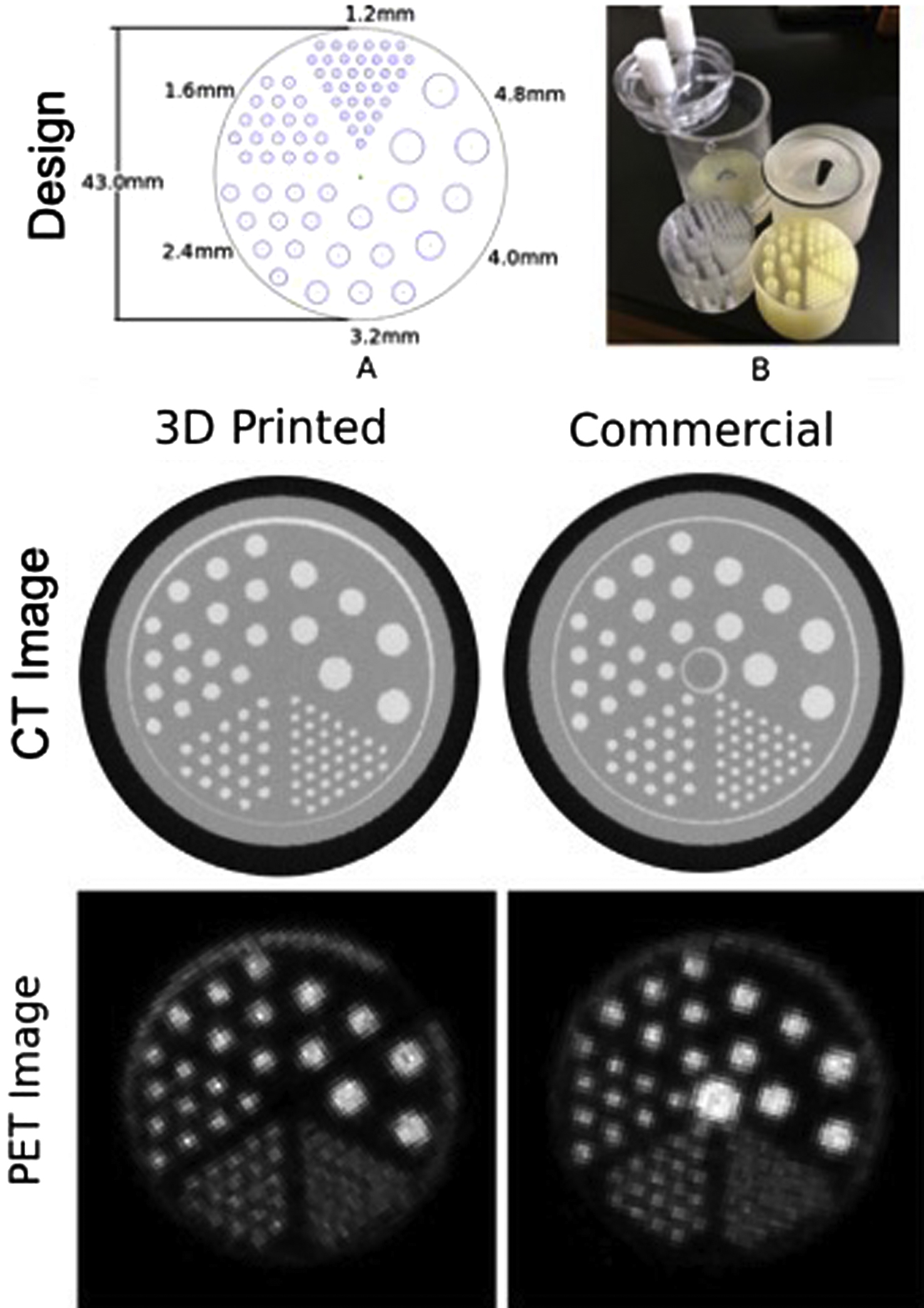
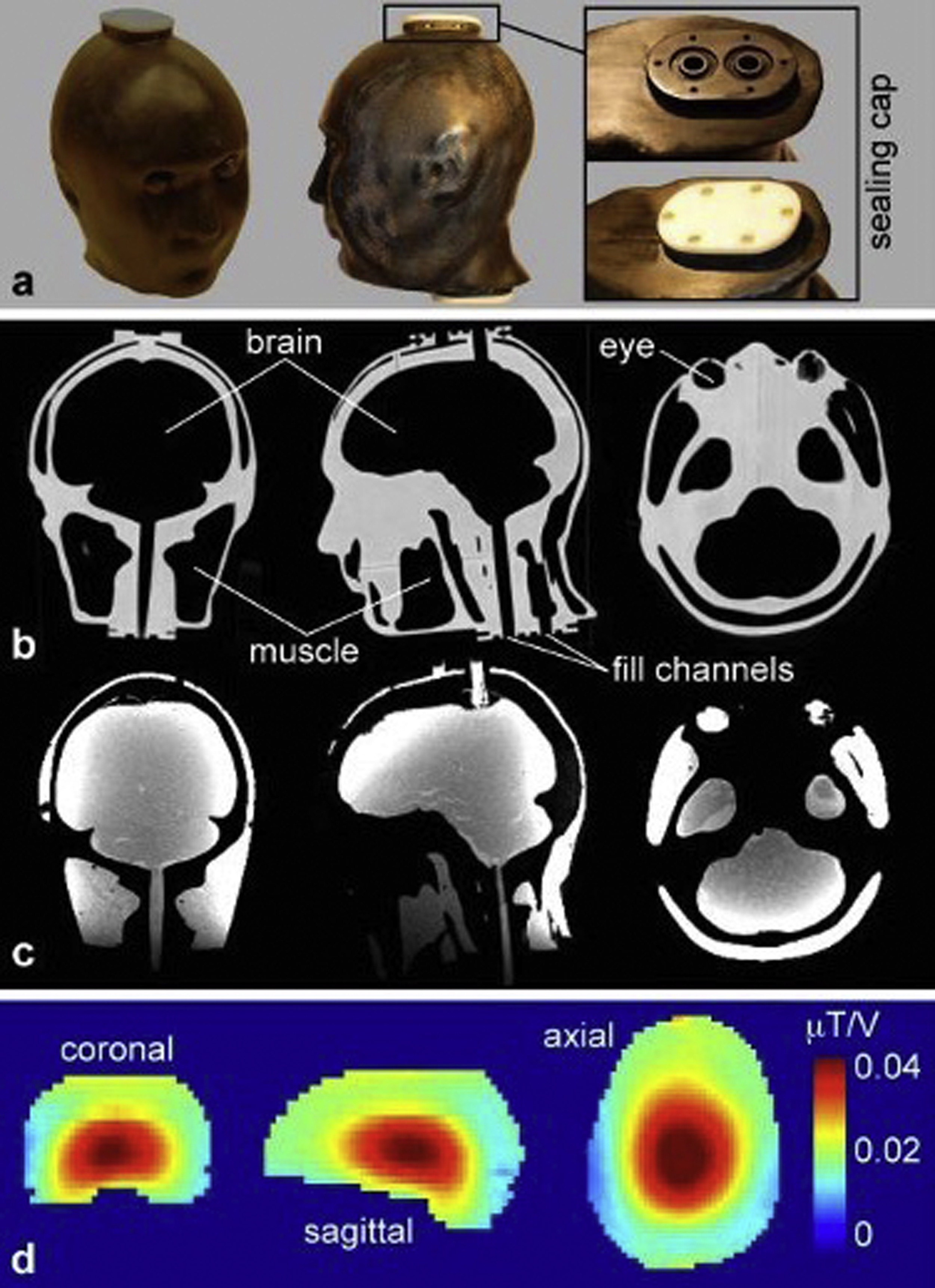
Fig. 14.1 shows a 3D printed version of a commercial phantom used to examine resolution, attenuation, and concentration in PET-CT. The 3D printed cylindrical container has many cylindrical holes of different diameter and spacing. The holes are filled with a radioactive fluid with known concentration of the given radioisotope of interest. This fluid can also contain predetermined concentrations of CT contrast agent (in this case containing iodine) designed to increase attenuation of CT photon beams. Images of a plane passing through the phantom show high intensity corresponding to the radioactive fluid–filled sources in the PET images and also high intensity corresponding to the high-attenuation fluid-filled cylinders in the CT images. (Note that for historical reasons related to use of film exposure and examination of what would be considered a “negative” exposure for diagnostic purposes, materials such as bone with high attenuation and which cast a low-signal shadow by blocking photons are shown as having a high intensity in planar X-ray and CT images.)
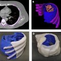
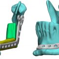
Fig. 14.2 shows images of a 3D printed anthropomorphic head phantom with four chambers designed to hold tissue-mimicking fluids or gels. In this application, the four chambers were filled with gels designed to have electrical properties relevant to different tissue types for the purpose of measuring radiofrequency-induced heating and consequent temperature increase during MRI. CT of the empty phantom shows relatively high attenuation (high image intensity) from the 3D printed material and low attenuation in the empty chambers. Once the chambers are filled, MR images show high-signal intensity from the gel-filled chambers and low-signal intensity from the 3D printed material. Because tissues with low water content (such as fat and bone) also have low electric permittivity and electric conductivity, the chambers were only used to represent tissues with high water content, including brain, muscle, and the vitreous humor within the eyes. These tissues were mimicked by combining water with agar as a gelling agent, sodium azide to prohibit bacterial growth, sodium chloride to control electrical conductivity, and polyethylene to control electric permittivity.
As mentioned above, using 3D printing methods to produce containers for more conventional tissue-mimicking materials can make use of decades of research into such materials. Since many tissue-mimicking materials are water based (as are many tissues), it is important to ensure that 3D printed containers are waterproof. Depending on the 3D printed material being used, methods of waterproofing may be necessary and can range from applying acetone to bond the outer material layer into a continuous waterproof surface, or coating (by dipping, spraying, or painting) the material with waterproofing substance.
The composition of a conventional tissue-mimicking material is highly dependent on the imaging modality, application, and tissue of interest. Table 14.3 summarizes a number of representative approaches to mimicking tissue with conventional materials for various modalities and purposes. Given the wide range of approaches used, the list is by no means comprehensive, but only representative.
| Desired Material Property | Material Composition(s) | Reference(s) |
|---|---|---|
| Increase scatter and attenuation of high-energy photons (X-ray, CT, SPECT, PET) |
| , , |
| Increase backscatter of ultrasonic waves | Incorporate microscopic glass spheres into liquid, silicone, or wax-based gel | , |
| Alter material stiffness and speed of ultrasonic waves | Adjust number of freeze/thaw cycles for PVA-C (cryogenic PVA) | , |
| Increase attenuation of ultrasonic waves | Adjust concentration of condensed milk compared to water in gel | |
| Decrease T 1 (MRI) |
| , , |
| Decrease T 2 (MRI) |
| , |
| Increase electrical conductivity | Increase concentration of NaCl in liquid or gel | , |
| Decrease electrical permittivity |
| , , |
Related posts:
 An Abbreviated History of Medical 3D Printing
 Image Segmentation and Nonuniformity Correction Methods
 Regulatory Perspectives for 3D Printing in Hospitals
 3D Printing in Nuclear Medicine and Radiation Therapy
 3D Printed Anatomic Models and Guides
 Medical Imaging Technologies and Imaging Considerations for 3D Printed Anatomic Models
Stay updated, free articles. Join our Telegram channel

Full access? Get Clinical Tree


